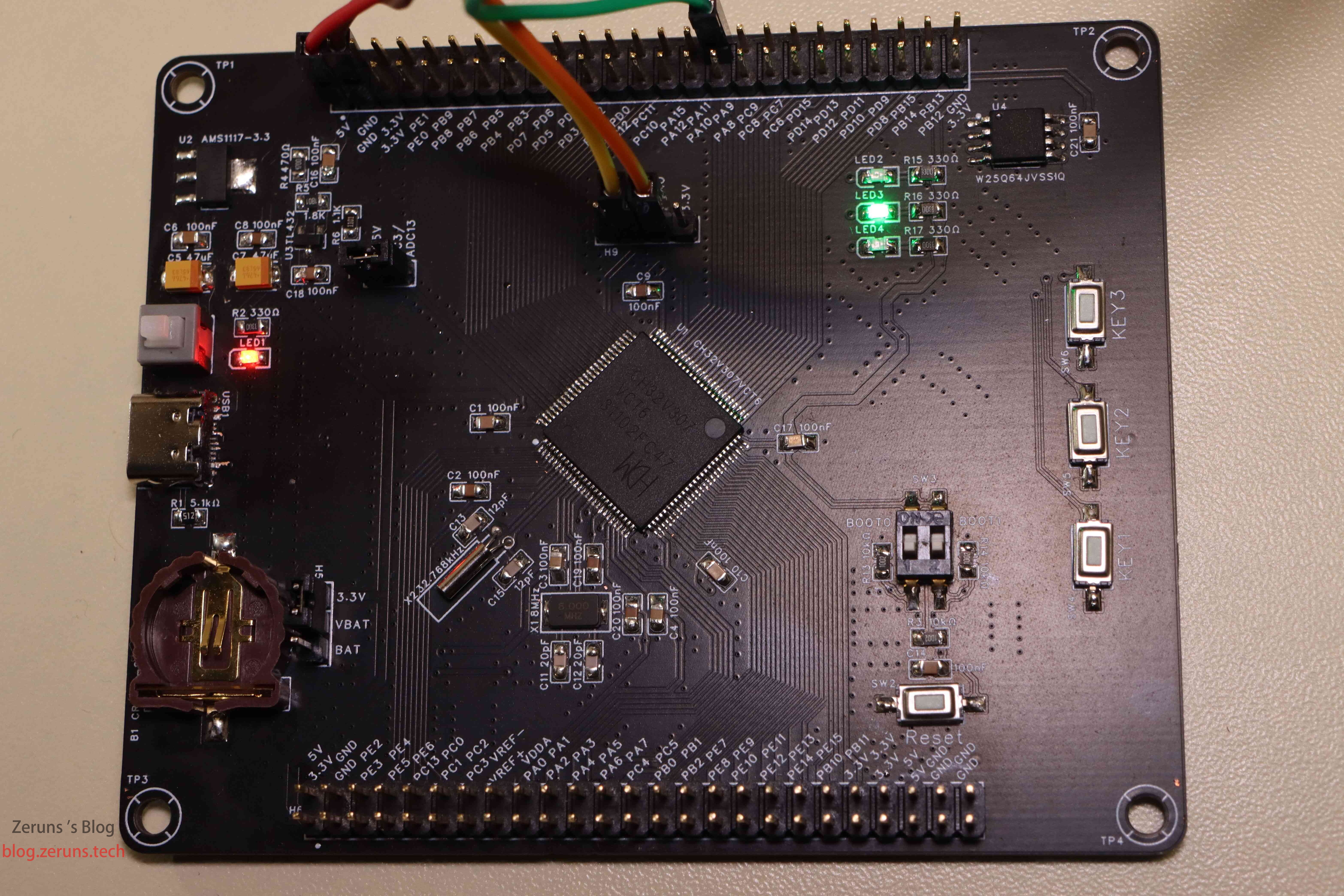
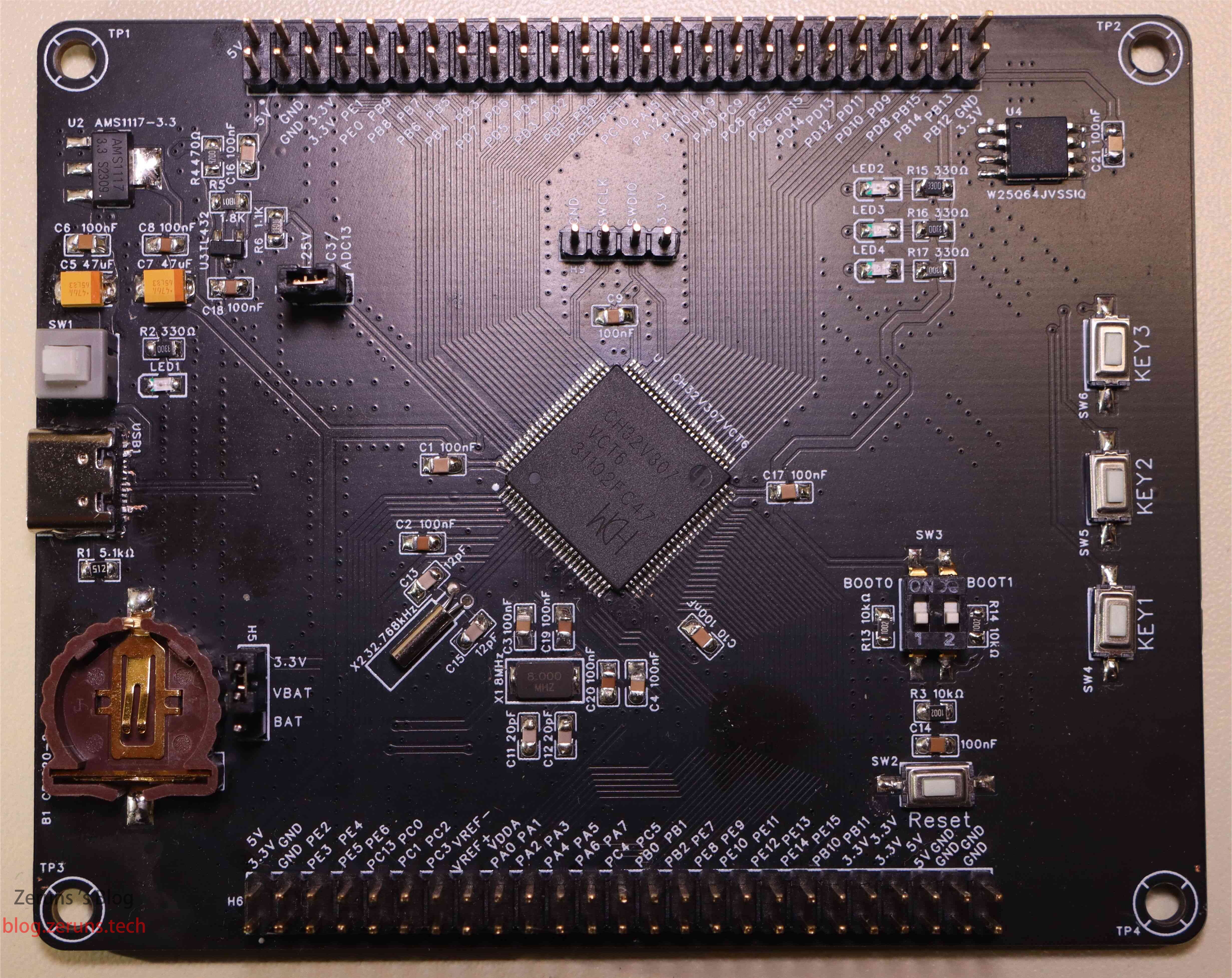
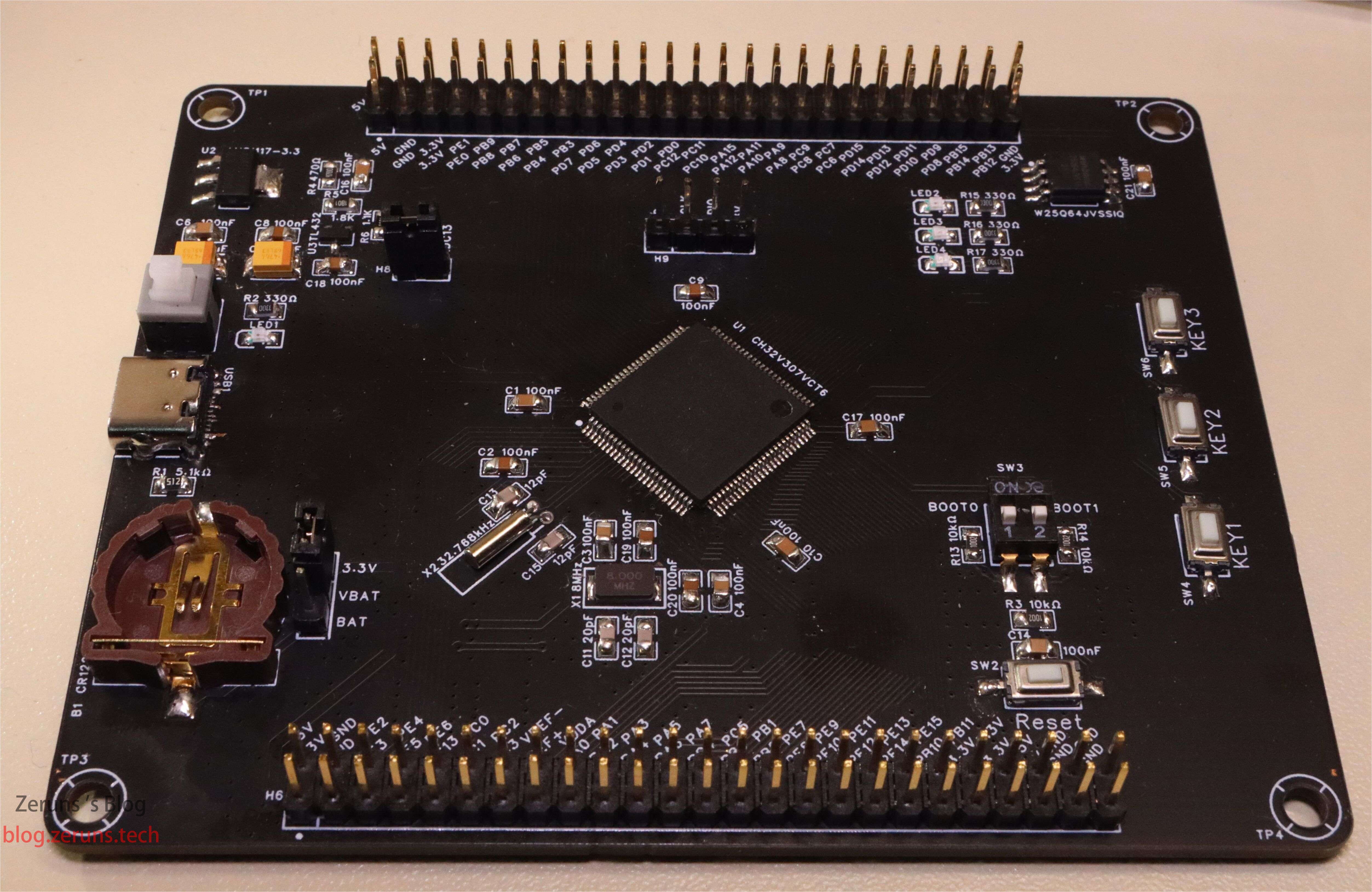
Placa de sistema mínima CH32V307VCT6 de QinHeng, con todos los pines de E/S expuestos, un conector USB Tipo-C con interfaz OTG USB 2.0 de velocidad completa, un chip Flash modelo W25Q64 de 64 Mbits conectado al interfaz SPI2, un regulador de voltaje TL432 de 1,25 V (medido en 1,246 V aproximadamente) que puede conectarse a AD13 de PC3 mediante un jumper, y una referencia de 3,29 V que puede conectarse al voltaje de referencia VREF del ADC mediante una resistencia de 0 Ω.
- Diseñé una placa de sistema mínima para MSP430F149 y la liberé como código abierto: https://blog.zeruns.com/archives/713.html
- Placa de sistema mínima STM32F030C8T6 y luces de desplazamiento (esquemático y PCB): https://blog.zeruns.com/archives/715.html
Grupo de discusión sobre electrónica y microcontroladores: 2169025065
Introducción al CH32V307VCT6
La serie CH32V está basada en microcontroladores industriales de propósito general de 32 bits RISC-V QingKe. Todos los productos incluyen un área de pila de hardware, entrada rápida de interrupciones y otros diseños que mejoran significativamente la velocidad de respuesta a interrupciones en comparación con el estándar. La serie CH32V303_305_307 utiliza el núcleo V4F, compatible con el conjunto de instrucciones de coma flotante de precisión simple, ofreciendo un mayor rendimiento de cálculo. En cuanto a funciones, admite una frecuencia de reloj de 144 MHz sin espera, y proporciona una estructura de recursos adaptada a diferentes aplicaciones, como 8 puertos USART/UART, 4 temporizadores para motores, interfaz USB 2.0 de alta velocidad (480 Mbps) con transceptor PHY integrado, MAC de Ethernet Gigabit, etc.
Introducción oficial del producto en el sitio web de QinHeng: https://url.zeruns.com/Hcd8p
Solicitud gratuita de muestras (envío a pagar): https://url.zeruns.com/x67TF
Descarga del manual del chip: https://url.zeruns.com/hDzqw Código de extracción: cn7c
Imágenes reales
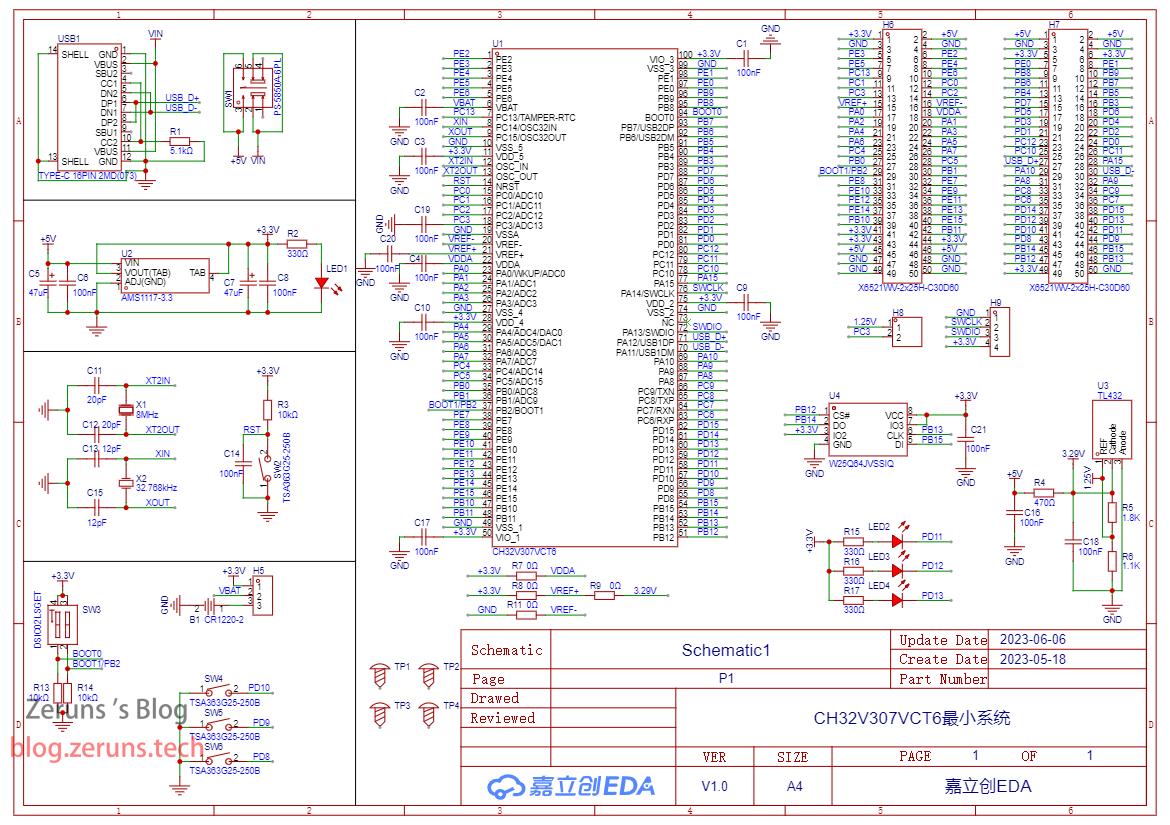
Esquemático
El conector Tipo-C en la imagen tiene un problema: CC1 y CC2 deben tener resistencias de 5,1 kΩ cada una conectadas a tierra. Al conectarlas en paralelo, causa problemas de alimentación con cables Emark. El proyecto en la plataforma de código abierto de LCSC ya ha sido corregido.
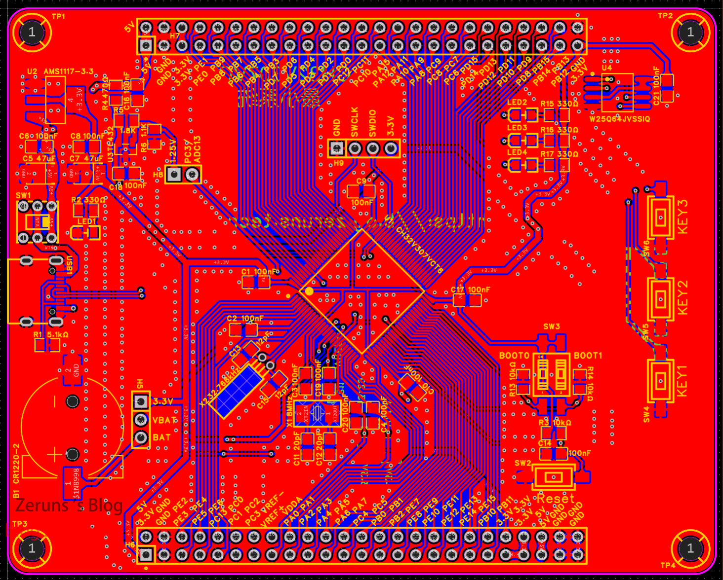
PCB
Capa superior:
La referencia de voltaje de 1,25 V del TL432 (medida en 1,246 V aproximadamente) puede conectarse al pin ADC13 de GPIOPC3 mediante un jumper en el conector H8.
SW3 controla los pines de arranque BOOT0 y BOOT1, permitiendo configurar el modo de arranque (ver sección 2.5.2 del manual del chip sobre memoria interna y modos de arranque). Ambos deben estar en nivel bajo (apagado).
El conector de pin H9 se utiliza para programar con WCH-Link.
El conector de pin H5 selecciona la fuente de alimentación del pin VBAT. Si no hay batería, se conecta a 3,3 V mediante un jumper; si hay batería, se conecta a BAT.
Capa inferior:
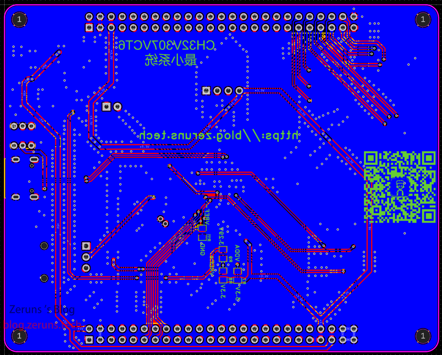
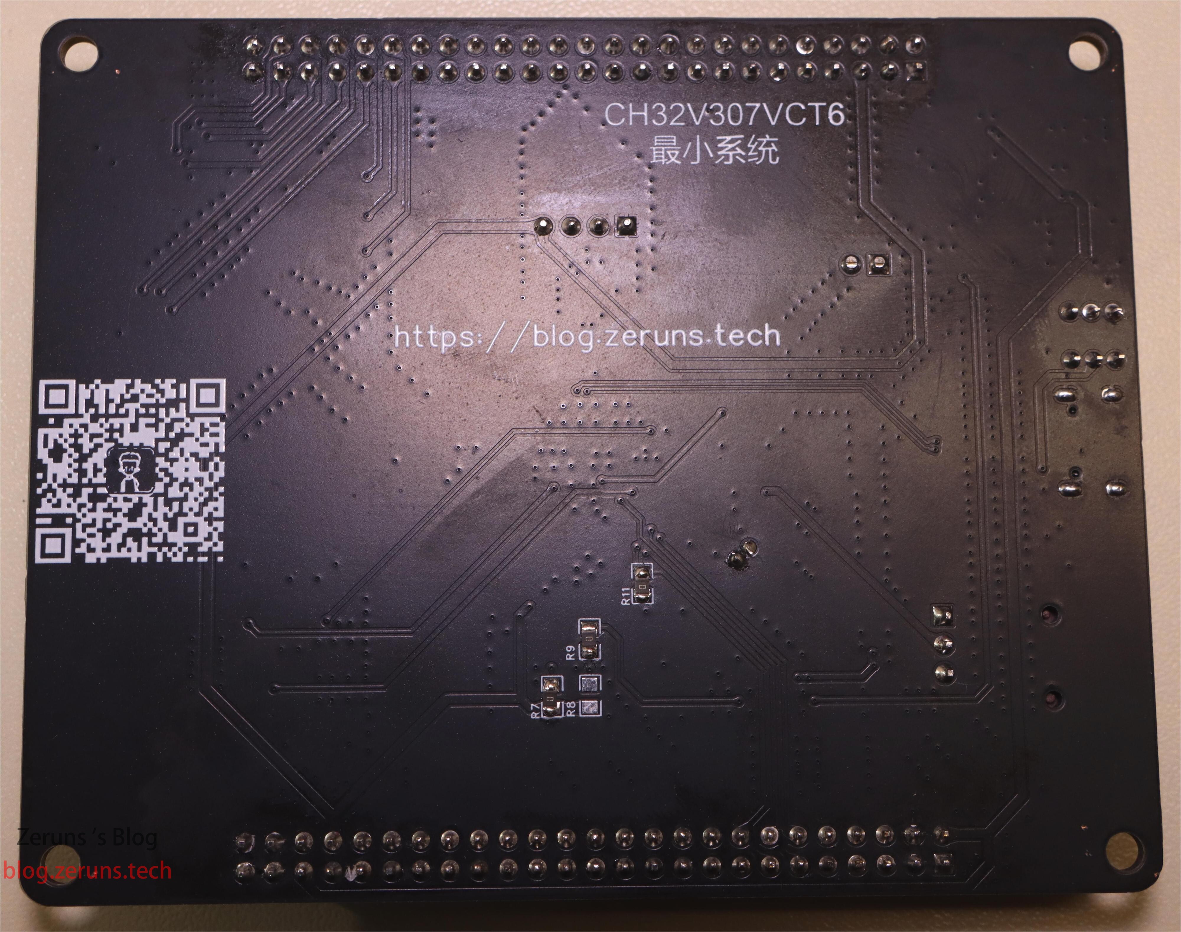
Si no se requiere alimentación externa para VDDA y VREF, deben colocarse resistencias de 0 Ω en R11 y R7 en la parte inferior. Luego, VREF+ puede seleccionarse mediante R8 y R9 para conectarse al voltaje de 3,3 V del LDO o a la referencia de 3,29 V del TL432. Normalmente se conecta R9 y se deja el otro sin conectar.
Enlaces de compra de componentes
- Muestras de resistencias 0805: https://u.jd.com/DzK9k0O
- Muestras de condensadores 0805: https://s.click.taobao.com/cTZzzDu
- CH32V307VCT6: https://s.click.taobao.com/5SjzzDu
- W25Q64JV: https://s.click.taobao.com/YAv6NEu
- TL432: https://s.click.taobao.com/t3AzzDu
- WCH-Link: https://s.click.taobao.com/m6KyzDu
- Pines de cabecera: https://u.jd.com/DbKUBDu
Se recomienda comprar componentes en la tienda LCSC. Enlace de registro con descuento: https://activity.szlcsc.com/invite/D03E5B9CEAAE70A4.html
Todos los componentes de la placa están disponibles en la tienda LCSC. En el enlace del proyecto de código abierto, en la lista de materiales, puedes hacer clic en “Agregar al carrito en LCSC” para importar todos los componentes utilizados.
Código de ejemplo
Enlace de descarga del proyecto completo: https://url.zeruns.com/2q4tX Código de extracción: 9527
Enlace del proyecto en la plataforma de código abierto de LCSC: https://url.zeruns.com/Avda8
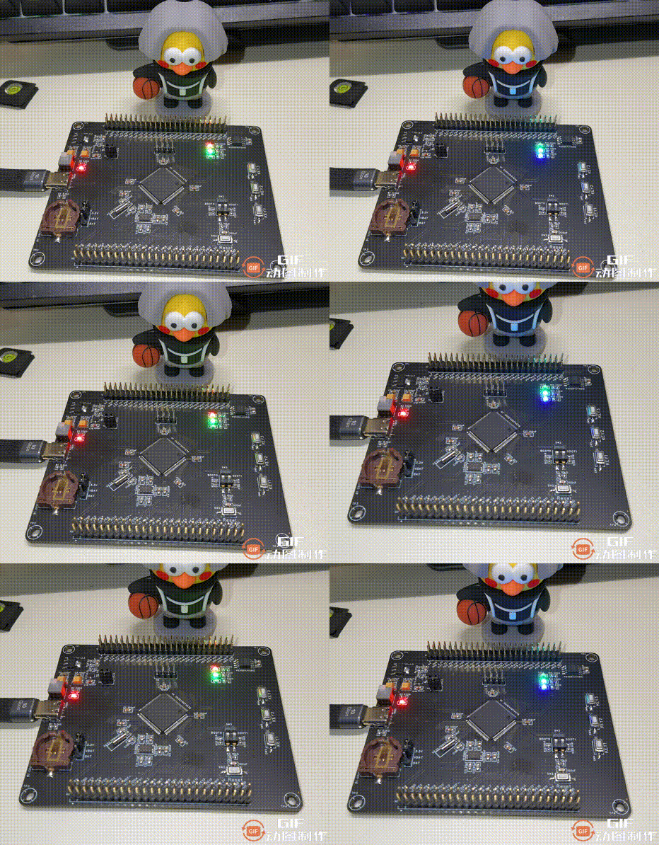
El ejemplo utiliza el sistema Harmony LiteOS-M. En el proyecto se crean 3 tareas: LED2 parpadea cada 500 ms, LED3 cada 1 segundo y LED4 cada 2 segundos. (La animación de arriba está acelerada 1.5x)
El proyecto debe abrirse con el software MounRiver Studio.
Código de main.c:
/*
 * Copyright (c) 2013-2019 Huawei Technologies Co., Ltd. All rights reserved.
 * Copyright (c) 2020-2021 Huawei Device Co., Ltd. All rights reserved.
 *
 * Redistribution and use in source and binary forms, with or without modification,
 * are permitted provided that the following conditions are met:
 *
 * 1. Redistributions of source code must retain the above copyright notice, this list of
 *    conditions and the following disclaimer.
 *
 * 2. Redistributions in binary form must reproduce the above copyright notice, this list
 *    of conditions and the following disclaimer in the documentation and/or other materials
 *    provided with the distribution.
 *
 * 3. Neither the name of the copyright holder nor the names of its contributors may be used
 *    to endorse or promote products derived from this software without specific prior written
 *    permission.
 *
 * THIS SOFTWARE IS PROVIDED BY THE COPYRIGHT HOLDERS AND CONTRIBUTORS
 * "AS IS" AND ANY EXPRESS OR IMPLIED WARRANTIES, INCLUDING, BUT NOT LIMITED TO,
 * THE IMPLIED WARRANTIES OF MERCHANTABILITY AND FITNESS FOR A PARTICULAR
 * PURPOSE ARE DISCLAIMED. IN NO EVENT SHALL THE COPYRIGHT HOLDER OR
 * CONTRIBUTORS BE LIABLE FOR ANY DIRECT, INDIRECT, INCIDENTAL, SPECIAL,
 * EXEMPLARY, OR CONSEQUENTIAL DAMAGES (INCLUDING, BUT NOT LIMITED TO,
 * PROCUREMENT OF SUBSTITUTE GOODS OR SERVICES; LOSS OF USE, DATA, OR PROFITS;
 * OR BUSINESS INTERRUPTION) HOWEVER CAUSED AND ON ANY THEORY OF LIABILITY,
 * WHETHER IN CONTRACT, STRICT LIABILITY, OR TORT (INCLUDING NEGLIGENCE OR
 * OTHERWISE) ARISING IN ANY WAY OUT OF THE USE OF THIS SOFTWARE, EVEN IF
 * ADVISED OF THE POSSIBILITY OF SUCH DAMAGE.
 */

#include "debug.h"
#include "los_tick.h"
#include "los_task.h"
#include "los_config.h"
#include "los_interrupt.h"
#include "los_debug.h"
#include "los_compiler.h"

/* Global define */
``````c
/* Variable Global */
__attribute__((aligned (8))) UINT8 g_memStart[LOSCFG_SYS_HEAP_SIZE];
UINT32 g_VlaueSp=0;

u8 i = 0,j=0,k=0;

/*********************************************************************
 * @fn      taskSampleEntry3
 *
 * @brief   Programa taskSampleEntry3.
 *
 * @return  none
 */
VOID taskSampleEntry3(VOID)
{
    while(1) {
      LOS_TaskDelay(2000);
      printf("taskSampleEntry3 running,task3 SP:%08x\n",__get_SP());
      GPIO_WriteBit(GPIOD, GPIO_Pin_13, (k == 0) ? (k = Bit_SET) : (k = Bit_RESET));
    }
}

/*********************************************************************
 * @fn      taskSampleEntry2
 *
 * @brief   Programa taskSampleEntry2.
 *
 * @return  none
 */
VOID taskSampleEntry2(VOID)
{
    while(1) {
      LOS_TaskDelay(1000);
      printf("taskSampleEntry2 running,task2 SP:%08x\n",__get_SP());
      GPIO_WriteBit(GPIOD, GPIO_Pin_12, (j == 0) ? (j = Bit_SET) : (j = Bit_RESET));
    }
}

/*********************************************************************
 * @fn      taskSampleEntry1
 *
 * @brief   Programa taskSampleEntry1.
 *
 * @return  none
 */
VOID taskSampleEntry1(VOID)
{
    while(1) {
      LOS_TaskDelay(500);
      printf("taskSampleEntry1 running,task1 SP:%08x\n",__get_SP());
      GPIO_WriteBit(GPIOD, GPIO_Pin_11, (i == 0) ? (i = Bit_SET) : (i = Bit_RESET));
    }

}
// https://blog.zeruns.com
/*********************************************************************
 * @fn      EXTI0_INT_INIT
 *
 * @brief   Inicializa la colección EXTI0.
 *
 * @return  none
 */
void EXTI0_INT_INIT(void)
{
  GPIO_InitTypeDef  GPIO_InitStructure={0};
  EXTI_InitTypeDef EXTI_InitStructure={0};
  NVIC_InitTypeDef NVIC_InitStructure={0};

  RCC_APB2PeriphClockCmd(RCC_APB2Periph_AFIO|RCC_APB2Periph_GPIOA,ENABLE);

  GPIO_InitStructure.GPIO_Pin = GPIO_Pin_0;
  GPIO_InitStructure.GPIO_Mode = GPIO_Mode_IPU;
  GPIO_Init(GPIOA, &GPIO_InitStructure);

   /* GPIOA ----> EXTI_Line0 */
  GPIO_EXTILineConfig(GPIO_PortSourceGPIOA,GPIO_PinSource0);
  EXTI_InitStructure.EXTI_Line=EXTI_Line0;
  EXTI_InitStructure.EXTI_Mode = EXTI_Mode_Interrupt;
  EXTI_InitStructure.EXTI_Trigger = EXTI_Trigger_Falling;
  EXTI_InitStructure.EXTI_LineCmd = ENABLE;
  EXTI_Init(&EXTI_InitStructure);

  NVIC_InitStructure.NVIC_IRQChannel = EXTI0_IRQn;
  NVIC_InitStructure.NVIC_IRQChannelPreemptionPriority = 0;
  NVIC_InitStructure.NVIC_IRQChannelSubPriority = 4;
  NVIC_InitStructure.NVIC_IRQChannelCmd = ENABLE;
  NVIC_Init(&NVIC_InitStructure);
}

void GPIO_INIT(void) {
    GPIO_InitTypeDef GPIO_InitStructure = { 0 };

    RCC_APB2PeriphClockCmd(RCC_APB2Periph_GPIOD, ENABLE);
    GPIO_InitStructure.GPIO_Pin = GPIO_Pin_12|GPIO_Pin_11|GPIO_Pin_13;
    GPIO_InitStructure.GPIO_Mode = GPIO_Mode_Out_PP;
    GPIO_InitStructure.GPIO_Speed = GPIO_Speed_50MHz;
    GPIO_Init(GPIOD, &GPIO_InitStructure);

}

/*********************************************************************
 * @fn      taskSample
 *
 * @brief   Programa taskSample.
 *
 * @return  none
 */
UINT32 taskSample(VOID) {
    UINT32 uwRet;
    UINT32 taskID1, taskID2, taskID3;
    TSK_INIT_PARAM_S stTask = { 0 };
    stTask.pfnTaskEntry = (TSK_ENTRY_FUNC) taskSampleEntry1;
    stTask.uwStackSize = 0X500;
    stTask.pcName = "taskSampleEntry1";
    stTask.usTaskPrio = 6;/* Alta prioridad */
    uwRet = LOS_TaskCreate(&taskID1, &stTask);
    if (uwRet != LOS_OK) {
        printf("create task1 failed\n");
    }

    stTask.pfnTaskEntry = (TSK_ENTRY_FUNC) taskSampleEntry2;
    stTask.uwStackSize = 0X500;
    stTask.pcName = "taskSampleEntry2";
    stTask.usTaskPrio = 7;/* Baja prioridad */
    uwRet = LOS_TaskCreate(&taskID2, &stTask);
    if (uwRet != LOS_OK) {
        printf("create task2 failed\n");
    }

    stTask.pfnTaskEntry = (TSK_ENTRY_FUNC) taskSampleEntry3;
        stTask.uwStackSize = 0X500;
        stTask.pcName = "taskSampleEntry3";
        stTask.usTaskPrio = 7;/* Baja prioridad */
        uwRet = LOS_TaskCreate(&taskID3, &stTask);
        if (uwRet != LOS_OK) {
            printf("create task3 failed\n");
        }
// https://blog.vpszj.cn
    EXTI0_INT_INIT();
    return LOS_OK;
}

/*********************************************************************
 * @fn      main
 *
 * @brief   Programa principal.
 *
 * @return  none
 */
LITE_OS_SEC_TEXT_INIT int main(void)
{
    unsigned int ret;

	NVIC_PriorityGroupConfig(NVIC_PriorityGroup_0);
    SystemCoreClockUpdate();
    Delay_Init();
    GPIO_INIT();
	USART_Printf_Init(115200);

	printf("SystemClk:%d\r\n",SystemCoreClock);
	printf( "ChipID:%08x\r\n", DBGMCU_GetCHIPID() );

    ret = LOS_KernelInit();
    taskSample();
    if (ret == LOS_OK)
    {
        LOS_Start();
    }

    GPIO_WriteBit(GPIOC, GPIO_Pin_1,RESET);

    while (1) {
        __asm volatile("nop");
    }

}


/*********************************************************************
 * @fn      EXTI0_IRQHandler
 *
 * @brief   Esta función maneja el Handler EXTI0.
 *
 * @return  none
 */
void EXTI0_IRQHandler(void) __attribute__((interrupt("WCH-Interrupt-fast")));
void EXTI0_IRQHandler(void)
{
  /* La pila de interrupciones usa el valor establecido originalmente para llamar a main, separando la pila de interrupciones y la pila de hilos.
   * De esta manera, cuando un hilo salta a una interrupción, si la función de interrupción tiene una gran profundidad de anidamiento,
   * la pila del hilo no se llenará y desbordará. Pero con el método actual, los 16 registros caller guardados por el compilador
   * aún se presionan en la pila del hilo. Si se desea que los registros caller se presionen en la pila de interrupciones,
   * entonces la entrada y salida de la función de interrupción deben usar ensamblador, y solo se llama a la función de manejo de interrupción del usuario en el medio.
   * Véase el ejemplo ipq_entry en los_exc.S
   *  */
  GET_INT_SP();
  HalIntEnter();
  if(EXTI_GetITStatus(EXTI_Line0)!=RESET)
  {
    g_VlaueSp= __get_SP();
    printf("Run at EXTI:");
    printf("interruption sp:%08x\r\n",g_VlaueSp);
    HalDisplayTaskInfo();
    EXTI_ClearITPendingBit(EXTI_Line0);     /* Limpiar Flag */
  }
  HalIntExit();
  FREE_INT_SP();
}
Otros proyectos de código abierto recomendados
- Módulo de alimentación DCDC sincrónico ajustable SY8205 (esquemático y PCB): https://blog.zeruns.com/archives/717.html
- Concurso nacional de electrónica 2011 - Sistema de alimentación en paralelo de módulos de fuente conmutada: https://blog.zeruns.com/archives/718.html
- Concurso de alimentación 2007: Módulo DCDC elevador ajustable de 30 a 36V (UC3843): https://oshwhub.com/zeruns/36v-sheng-ya-dcdc-mo-kuai-uc3842
- Placa mínima STC12C5A60S2 / Control de temperatura y ventilador con microcontrolador 51: https://blog.zeruns.com/archives/721.html
- Plantilla de proyecto STM32F407 con biblioteca gráfica U8g2 portada: https://blog.zeruns.com/archives/722.html
Recomendados
- Recomendación de VPS/Servidores en la nube de alta relación calidad-precio y económicos: https://blog.vpszj.cn/archives/41.html
- Cómo crear un blog personal: https://blog.zeruns.com/archives/218.html
- Tutorial de creación de servidor de Minecraft: https://blog.zeruns.com/tag/mc/
- STM32 lee sensores de temperatura y humedad serie SHT3x: https://blog.zeruns.com/archives/700.html
- Usar VSCode en lugar de Keil para el desarrollo de STM32 y microcontroladores 51: https://blog.zeruns.com/archives/690.html
- Revisión de rendimiento de servidor dedicado de alta defensa en EE.UU. de Yuyun, 8 núcleos 16G 50M 200G defensa: https://blog.vpszj.cn/archives/1603.html
- Evaluación de rendimiento de VPS de alta defensa en Shiyan, Hubei de TeYuyun, 4 núcleos 8G 10M 100G defensa: https://blog.vpszj.cn/archives/1523.html