Open-source USB-C Input USB3.2 Docking Station with 4 USB3.2 Gen2 Ports + 2.5G Ethernet + TF/SD Card Reader, Supporting PD Fast Charging for Additional Power Supply. Input Voltage Range: 4-20V. Buck-Boost Circuit Regulates Output to 5.1V. Based on VL160+VL822+RTL8156BG+GL3224 Chips.
Open-Source USB 10Gbps Hub with 2.5Gbps Ethernet & TF/SD Card Reader
![]() This is my first time working on a high-speed PCB project. If there are any areas needing improvement or mistakes made, experts are welcome to provide guidance.
This is my first time working on a high-speed PCB project. If there are any areas needing improvement or mistakes made, experts are welcome to provide guidance.
![]() Also actively seeking job opportunities online! Employers in Guangzhou/Foshan interested in hiring can contact me. Check my open-source projects on LCEDA: https://oshwhub.com/zeruns/works
Also actively seeking job opportunities online! Employers in Guangzhou/Foshan interested in hiring can contact me. Check my open-source projects on LCEDA: https://oshwhub.com/zeruns/works
Project demonstration & design process video: https://www.bilibili.com/video/BV145G1z9Em2/
LCEDA Open-Source Link: https://url.zeruns.com/U9sCt
QQ Group for Electronics/MCU Discussions: 2169025065
Download links for project files at the end of the article!
Project Overview
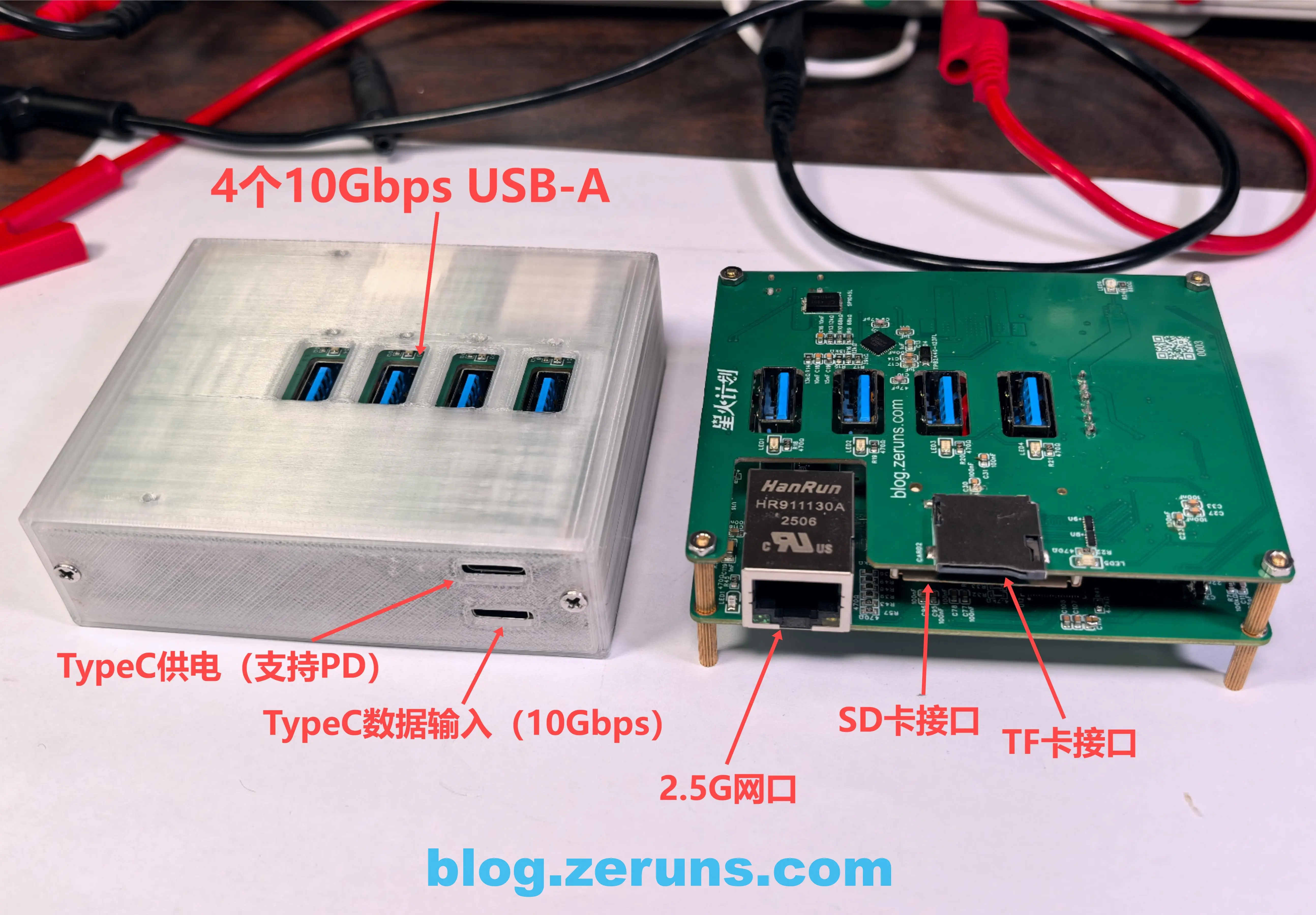
![]() This USB-C input USB3.2 docking station provides 4 USB3.2 (10Gbps) Type-A outputs (the input port is also 10Gbps, so the total speed remains 10Gbps), 1 2.5G Ethernet port, and TF/SD card readers.
This USB-C input USB3.2 docking station provides 4 USB3.2 (10Gbps) Type-A outputs (the input port is also 10Gbps, so the total speed remains 10Gbps), 1 2.5G Ethernet port, and TF/SD card readers.
![]() The 5V power supply uses a Buck-Boost circuit to regulate output to 5.1V (0.1V higher to compensate for line loss at high currents). Two Type-C inputs: one for data (also supports 5V power but not PD fast charging negotiation, connected to the Buck-Boost circuit to prevent voltage drop at high currents), and one dedicated power input (supports PD fast charging detection to trigger 20V input, then stepped down to 5.1V via Buck-Boost). The 5V power circuit supports up to 9.5A output current, with each USB-A port delivering up to 2A.
The 5V power supply uses a Buck-Boost circuit to regulate output to 5.1V (0.1V higher to compensate for line loss at high currents). Two Type-C inputs: one for data (also supports 5V power but not PD fast charging negotiation, connected to the Buck-Boost circuit to prevent voltage drop at high currents), and one dedicated power input (supports PD fast charging detection to trigger 20V input, then stepped down to 5.1V via Buck-Boost). The 5V power circuit supports up to 9.5A output current, with each USB-A port delivering up to 2A.
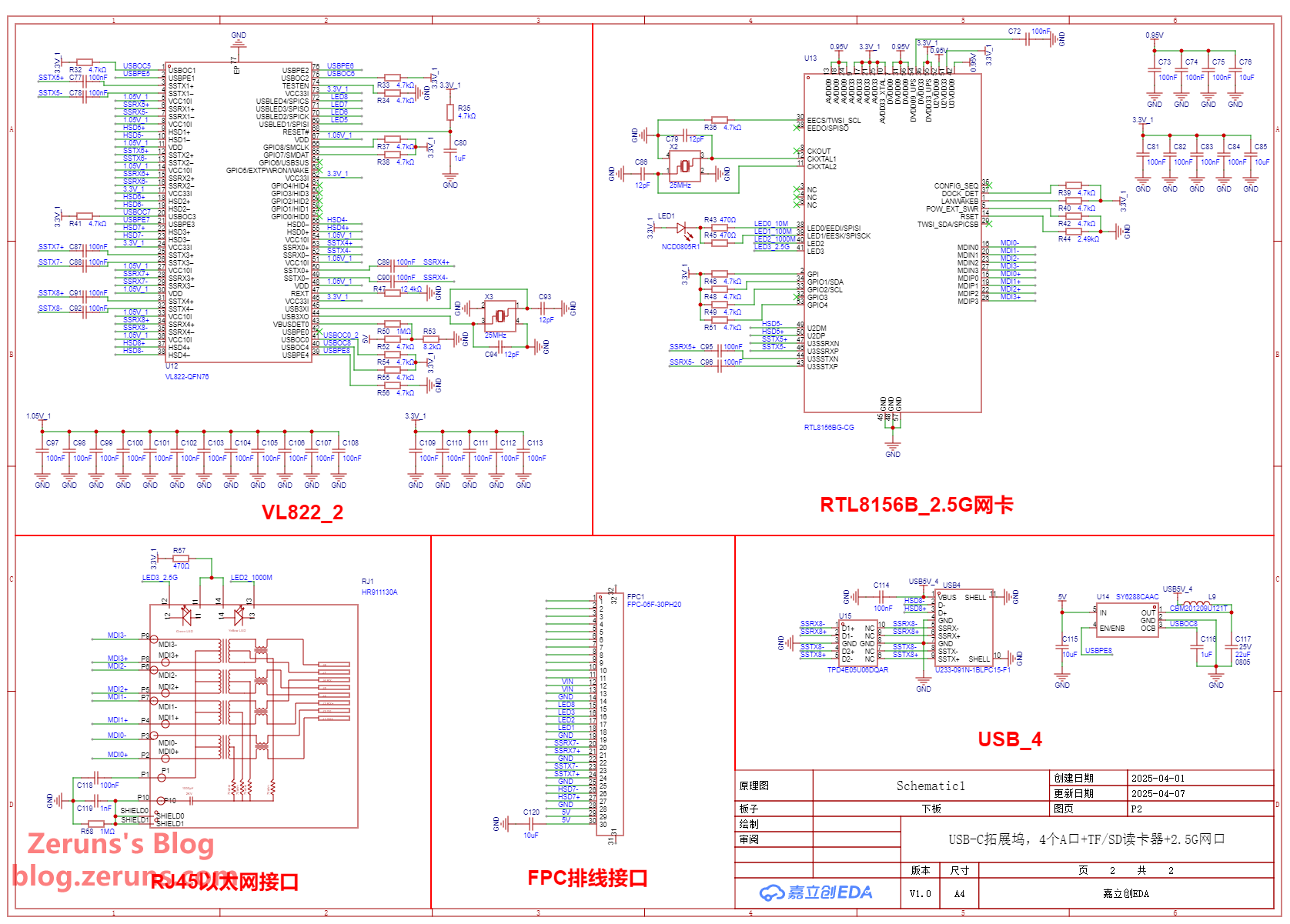
![]() Two VL822 chips are used. One VL822 has an unused USB interface that can be modified for additional features, such as adding another Type-A port or integrating a microcontroller with current/voltage sampling to monitor real-time power usage on all USB ports (planned originally but limited by PCB size constraints).
Two VL822 chips are used. One VL822 has an unused USB interface that can be modified for additional features, such as adding another Type-A port or integrating a microcontroller with current/voltage sampling to monitor real-time power usage on all USB ports (planned originally but limited by PCB size constraints).
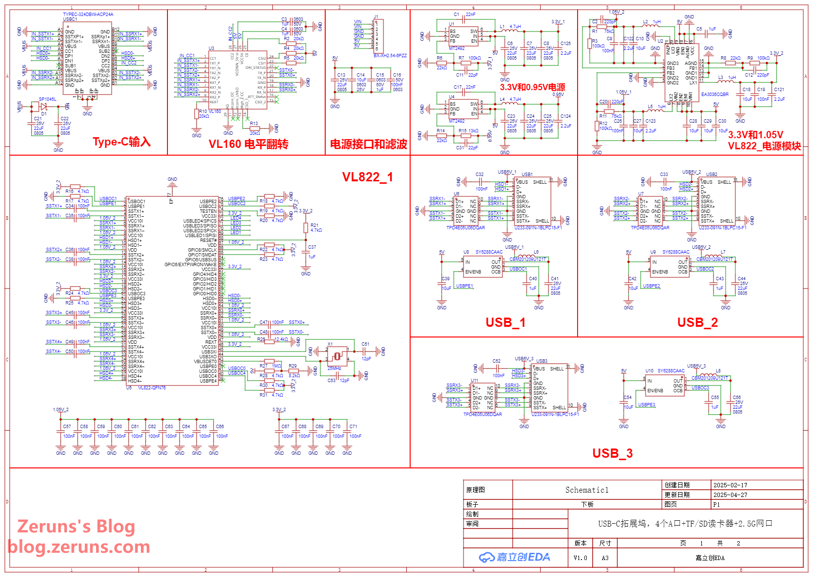
![]() The design uses a two-layer board: the upper board houses the 5V Buck-Boost power circuit and card reader circuit, while the lower board contains the USB HUB and 2.5G Ethernet circuits. Boards are connected via FPC and XH2.54 ribbon cables.
The design uses a two-layer board: the upper board houses the 5V Buck-Boost power circuit and card reader circuit, while the lower board contains the USB HUB and 2.5G Ethernet circuits. Boards are connected via FPC and XH2.54 ribbon cables.
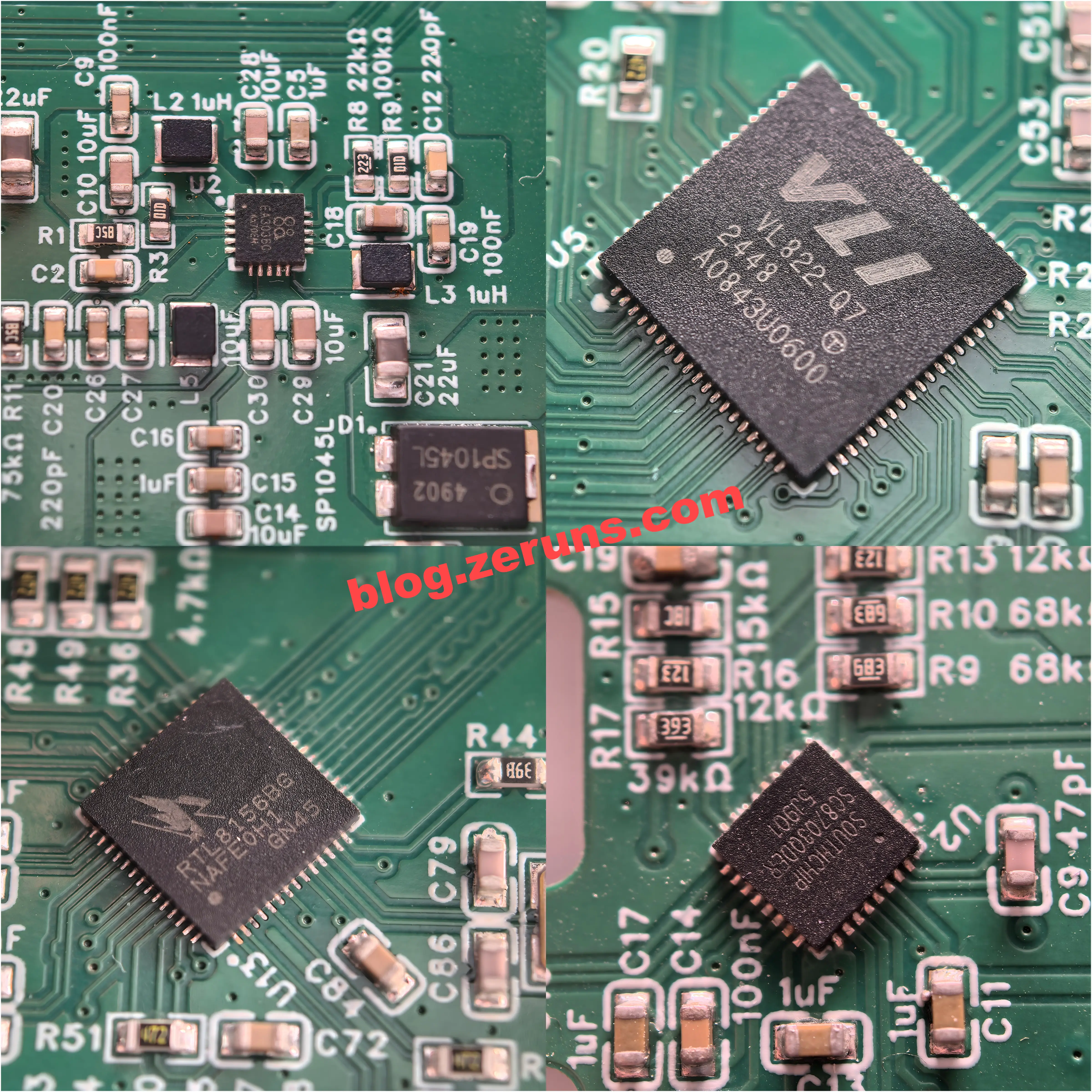
![]() Key chips used: VL160, VL822, RTL8156BG, GL3224, EA3036, MT2492, SC8703
Key chips used: VL160, VL822, RTL8156BG, GL3224, EA3036, MT2492, SC8703
![]() Inspired by this project: USB3.2 Dock with Independent Regulated Power Supply
Inspired by this project: USB3.2 Dock with Independent Regulated Power Supply
Docking Station Specifications
- Input Interface: USB-C
- Output Interfaces: USB-A, RJ45, TF, SD
- Max Input Speed: 10Gbps
- Max Output Speed: USB:10Gbps | RJ45:2.5Gbps
- Max Input Power: 5V@5A / 20V@5A
- Max Output Current (Type-A): 5V@2A (total up to 8A across all ports)
- Dimensions: 90 x 74 x 26.3 mm
Physical Photos
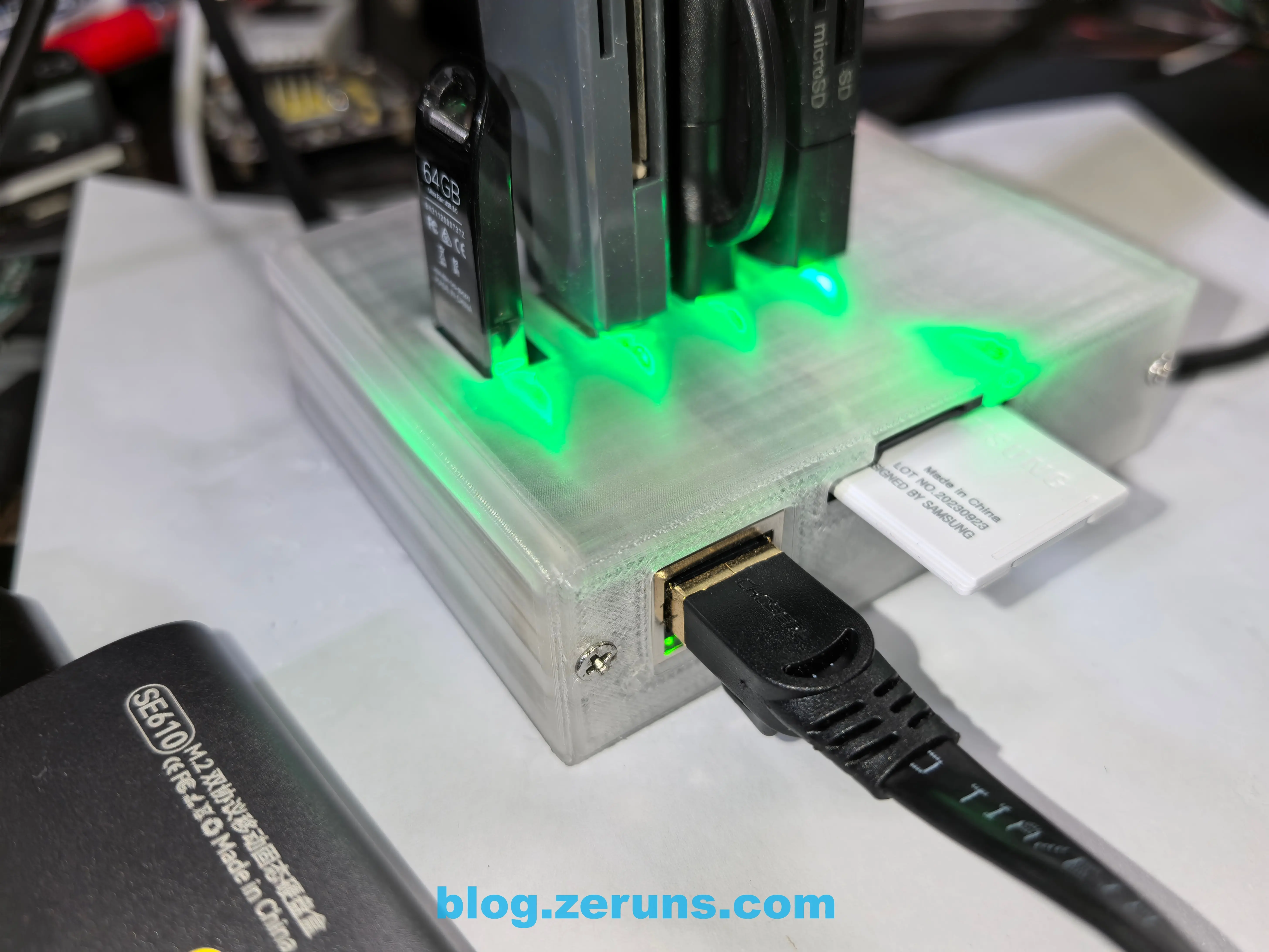
After installing the enclosure:
Power-on operation:
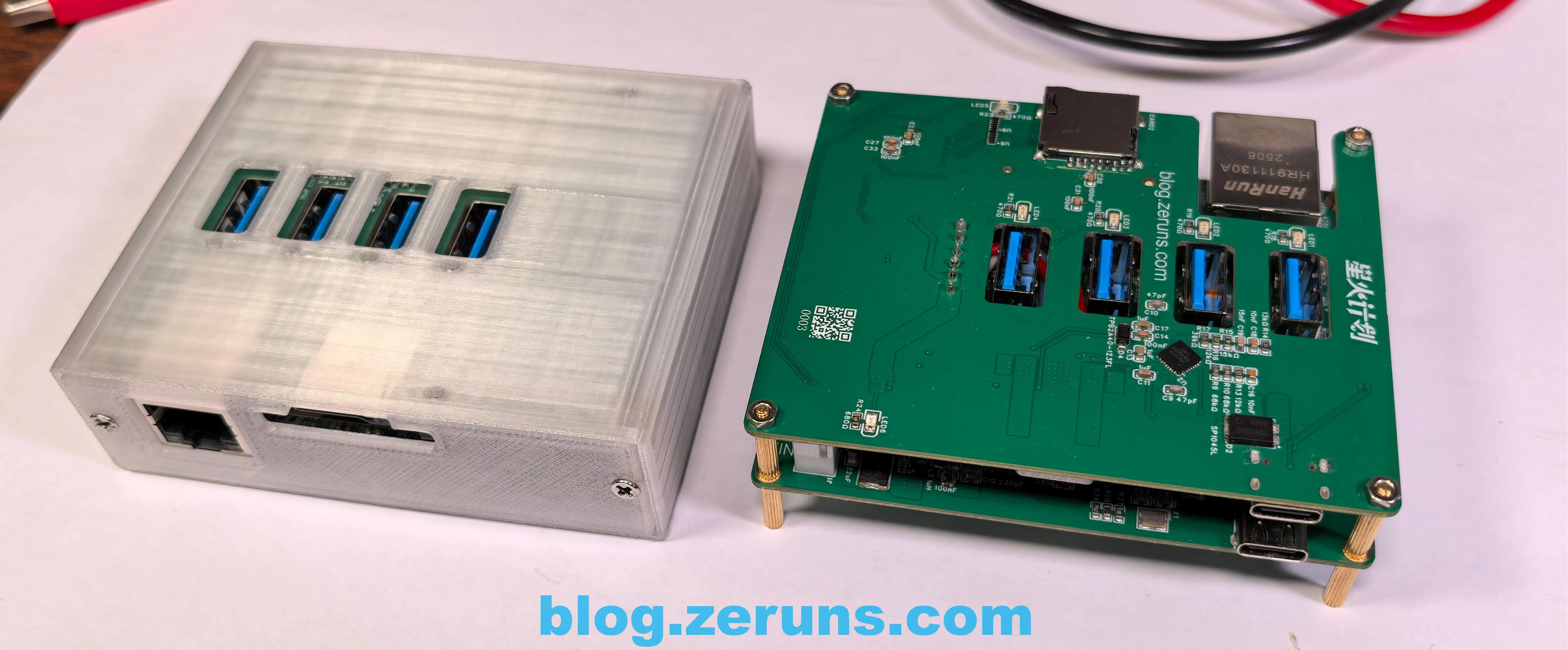
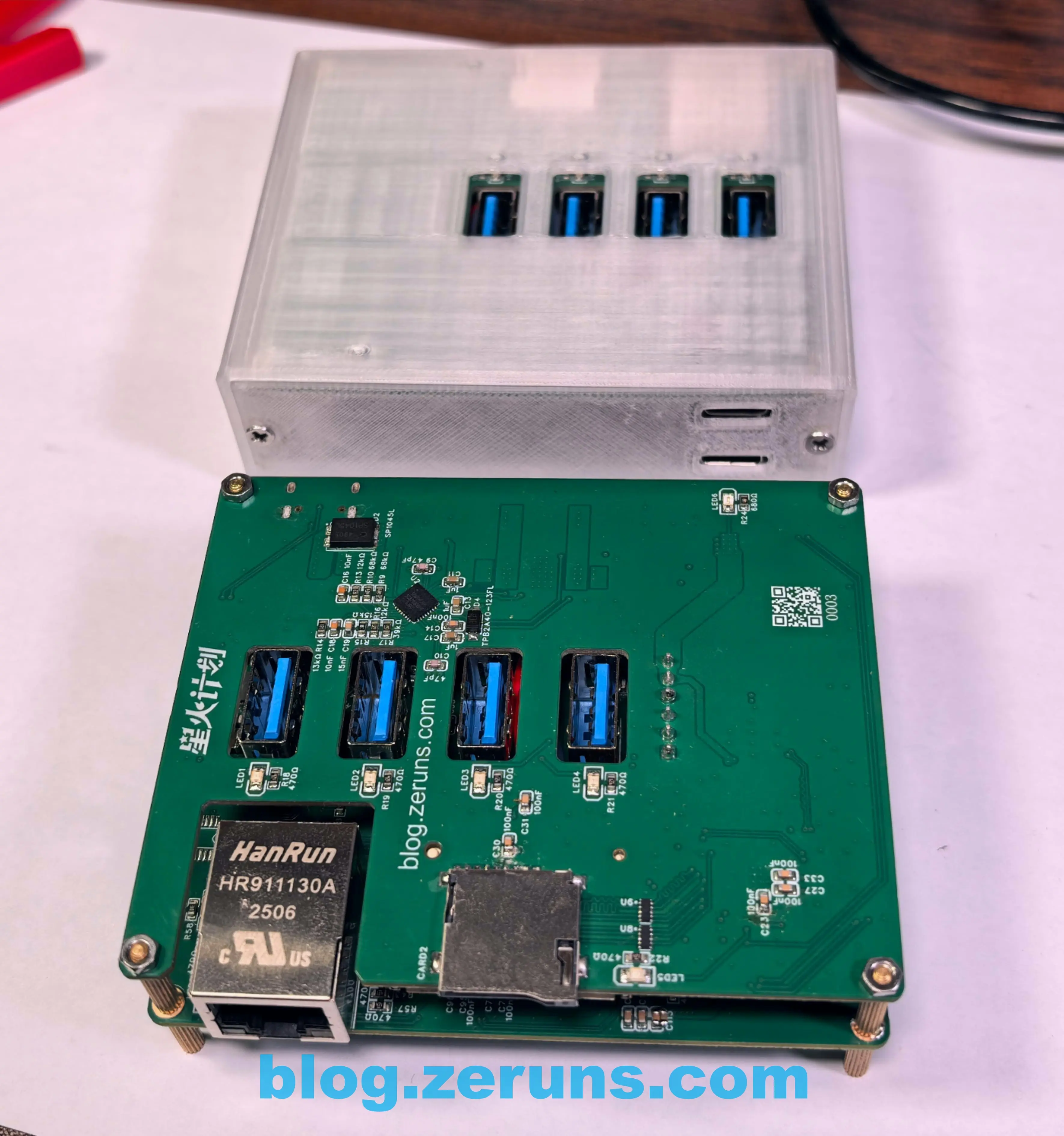
PCB details:
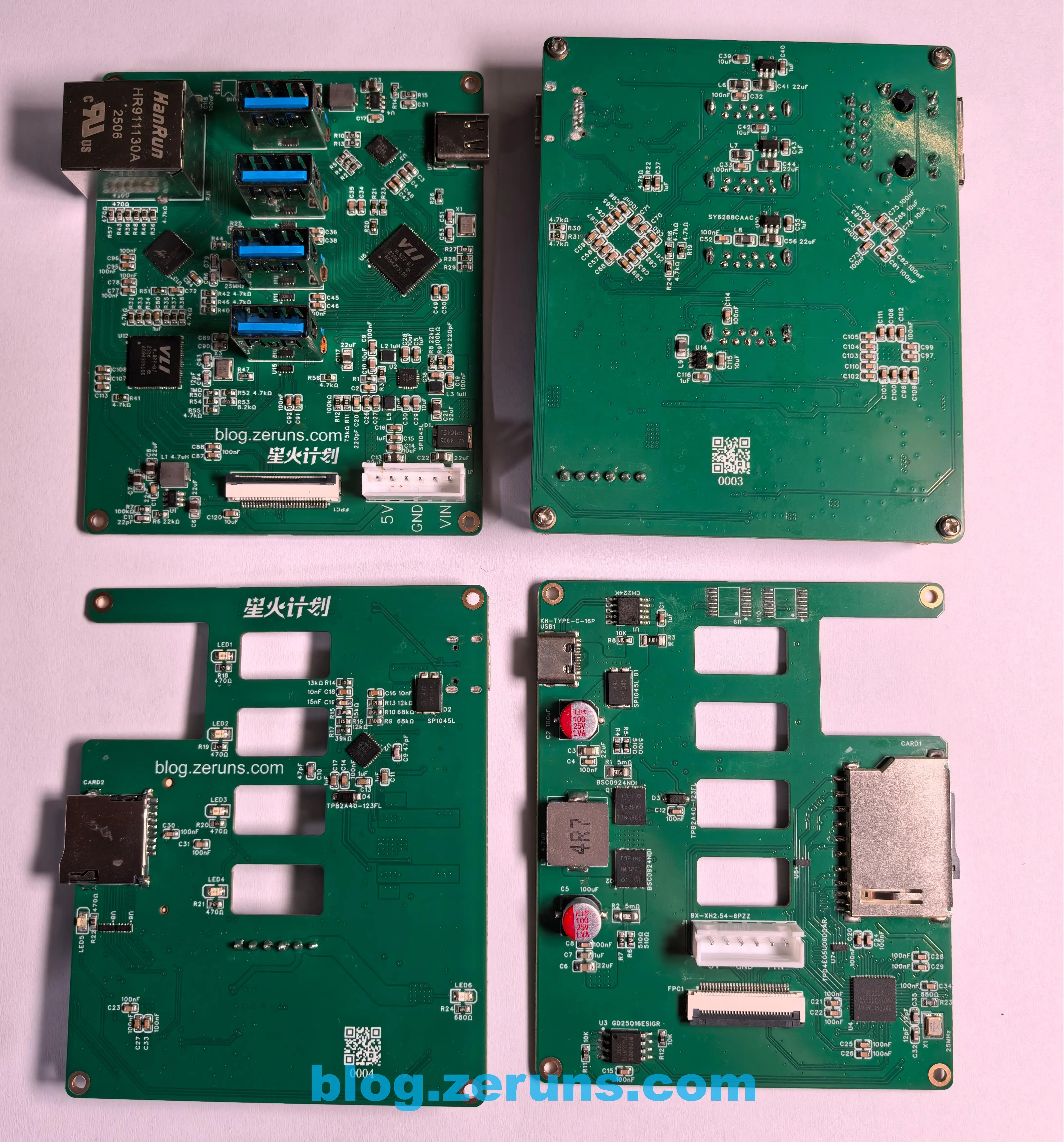
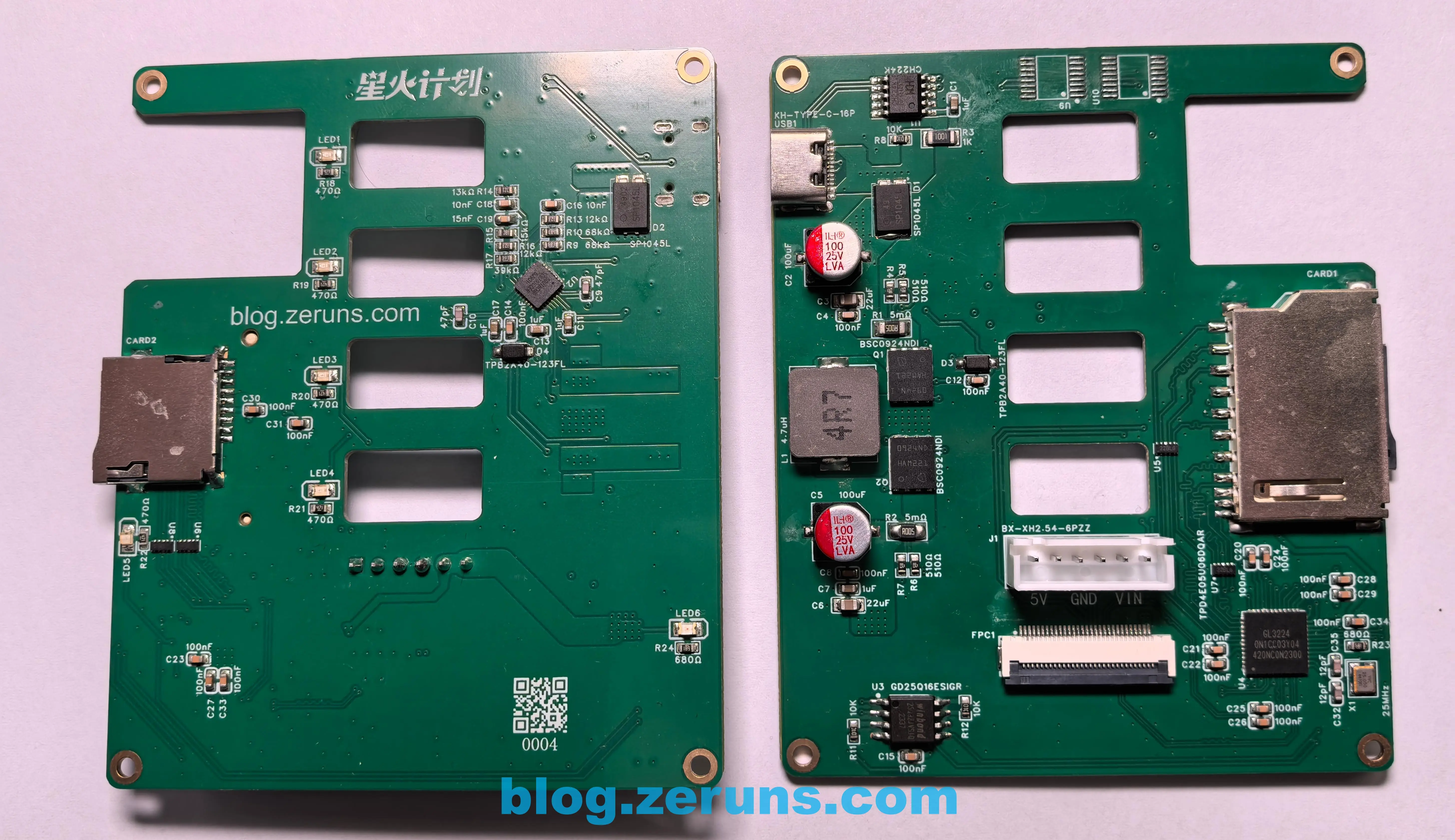
Lower board (front/back):
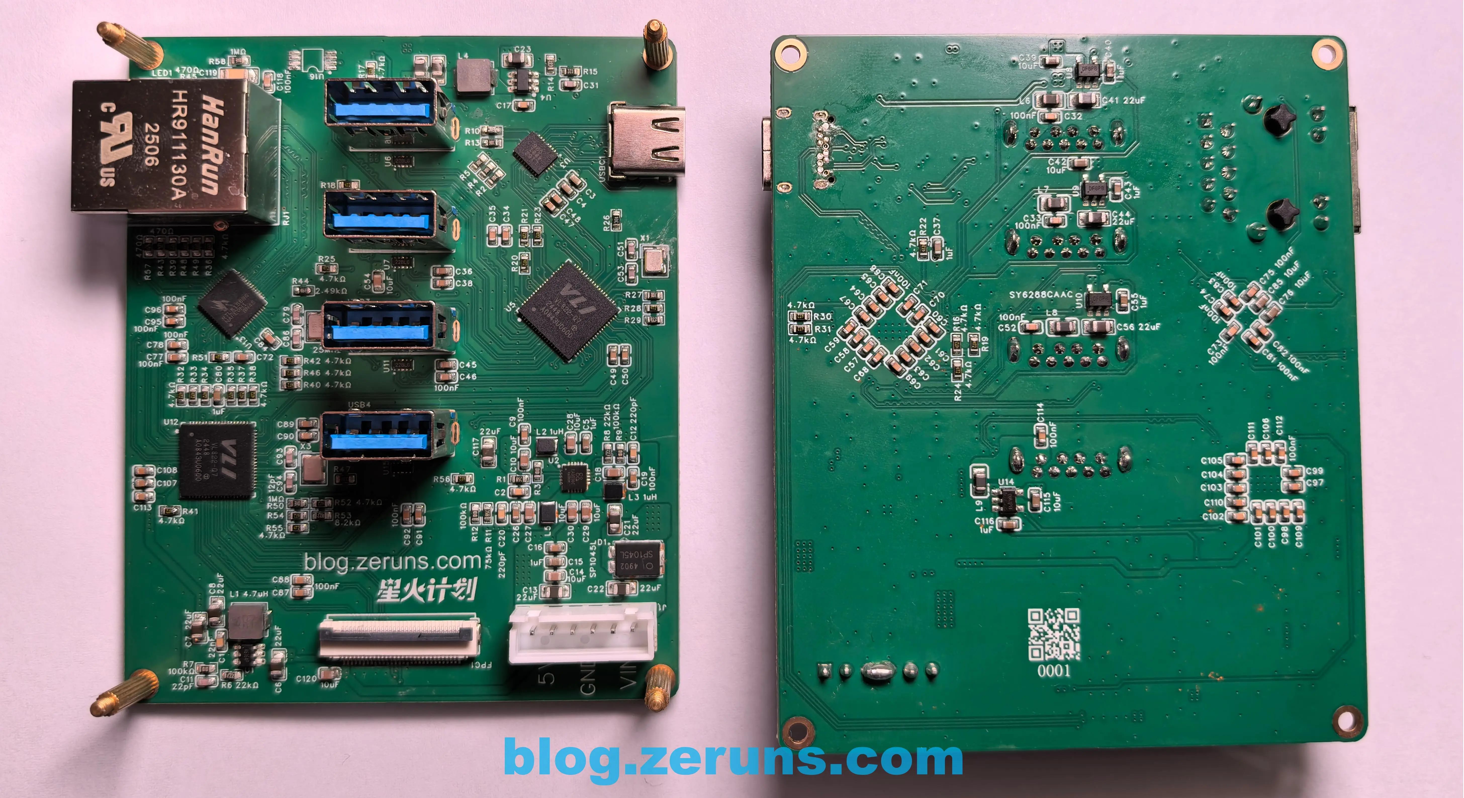
Upper board (front/back):
Hardware Implementation
When connected to a USB@5Gbps or higher-speed interface, the high-speed bus hardware architecture is:
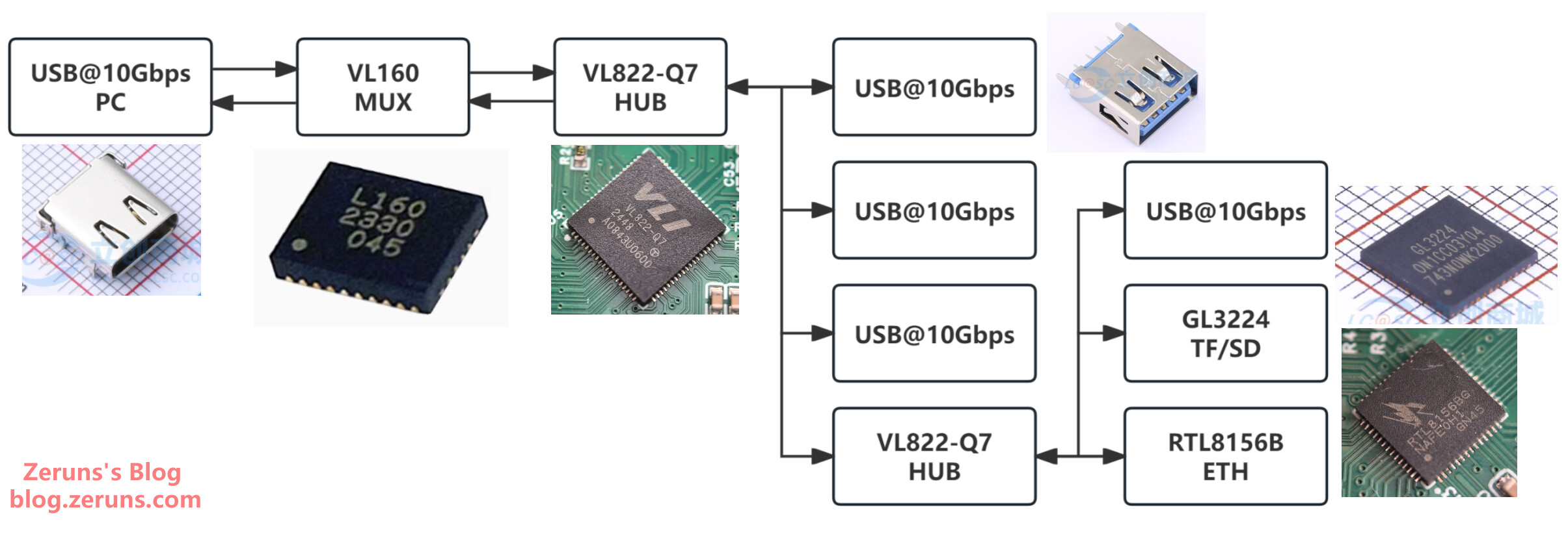
USB signals first pass through the VL160 level-shifting chip for reversible plug detection, then to the VL822 hub chip which splits 1 USB into 4.
For 480Mbps interfaces, signals bypass the VL160 and connect directly to the VL822 hub, limiting downstream speed to 480Mbps.
Power Hardware Architecture:
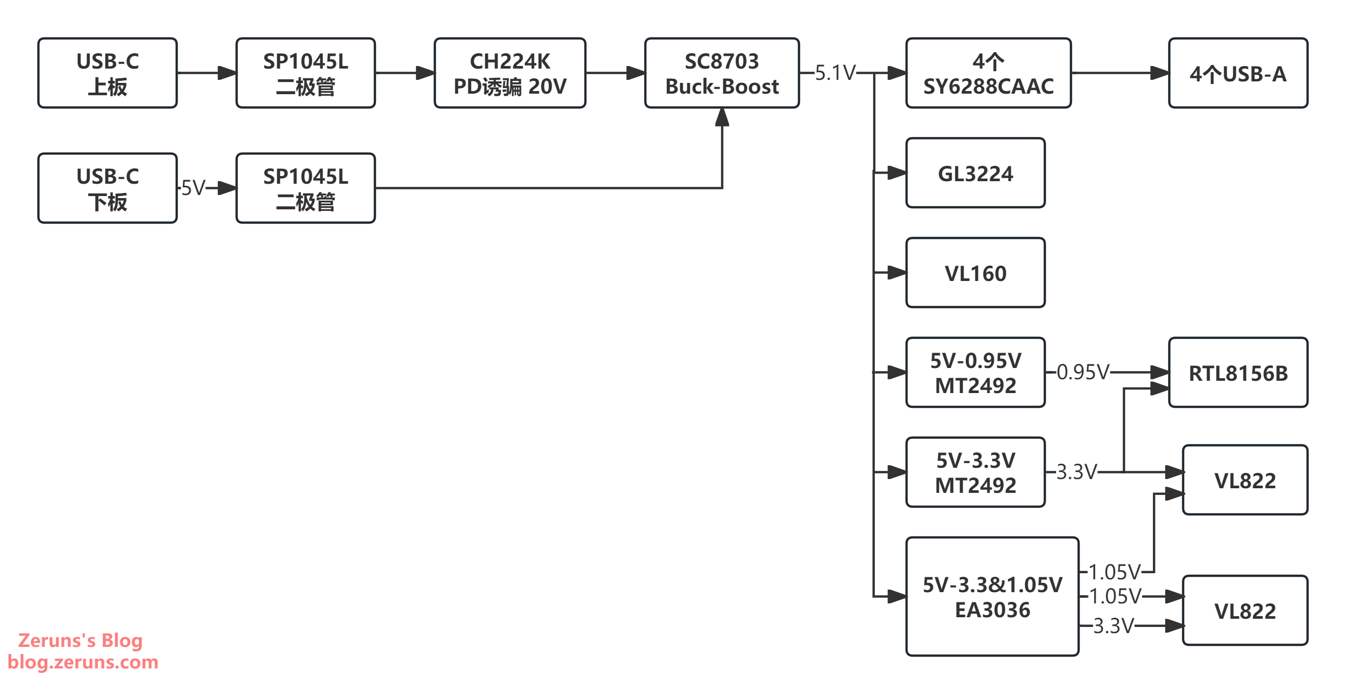
The SY6288CAAC power switch includes overcurrent protection. When load exceeds 2A, the switch disconnects power and pulls the OC pin low to notify the controller.
Hardware Performance Tests
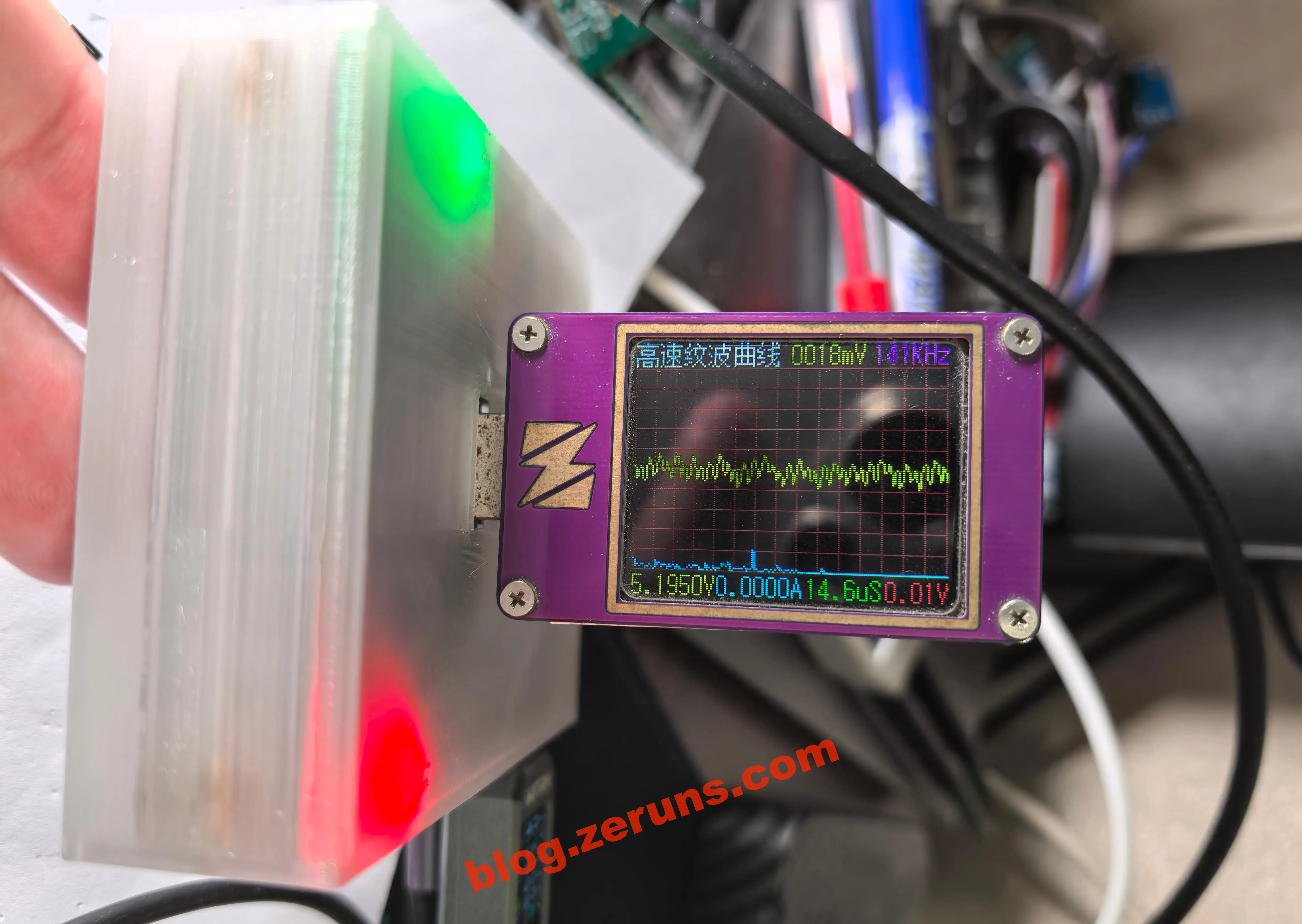
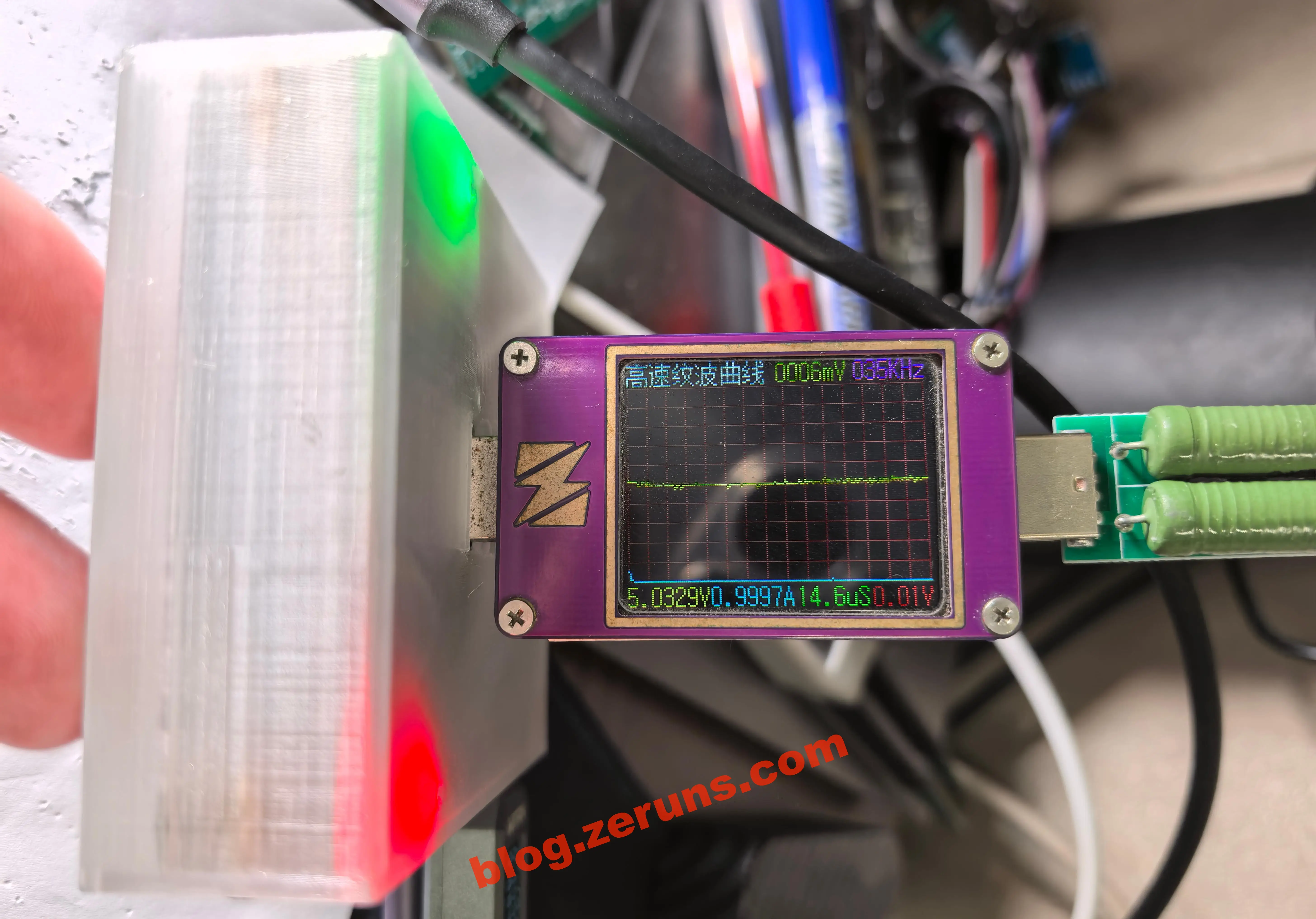
Type-A Port Output Ripple Test
-
No-load ripple: ~18mV
-
1A load ripple: ~6mV
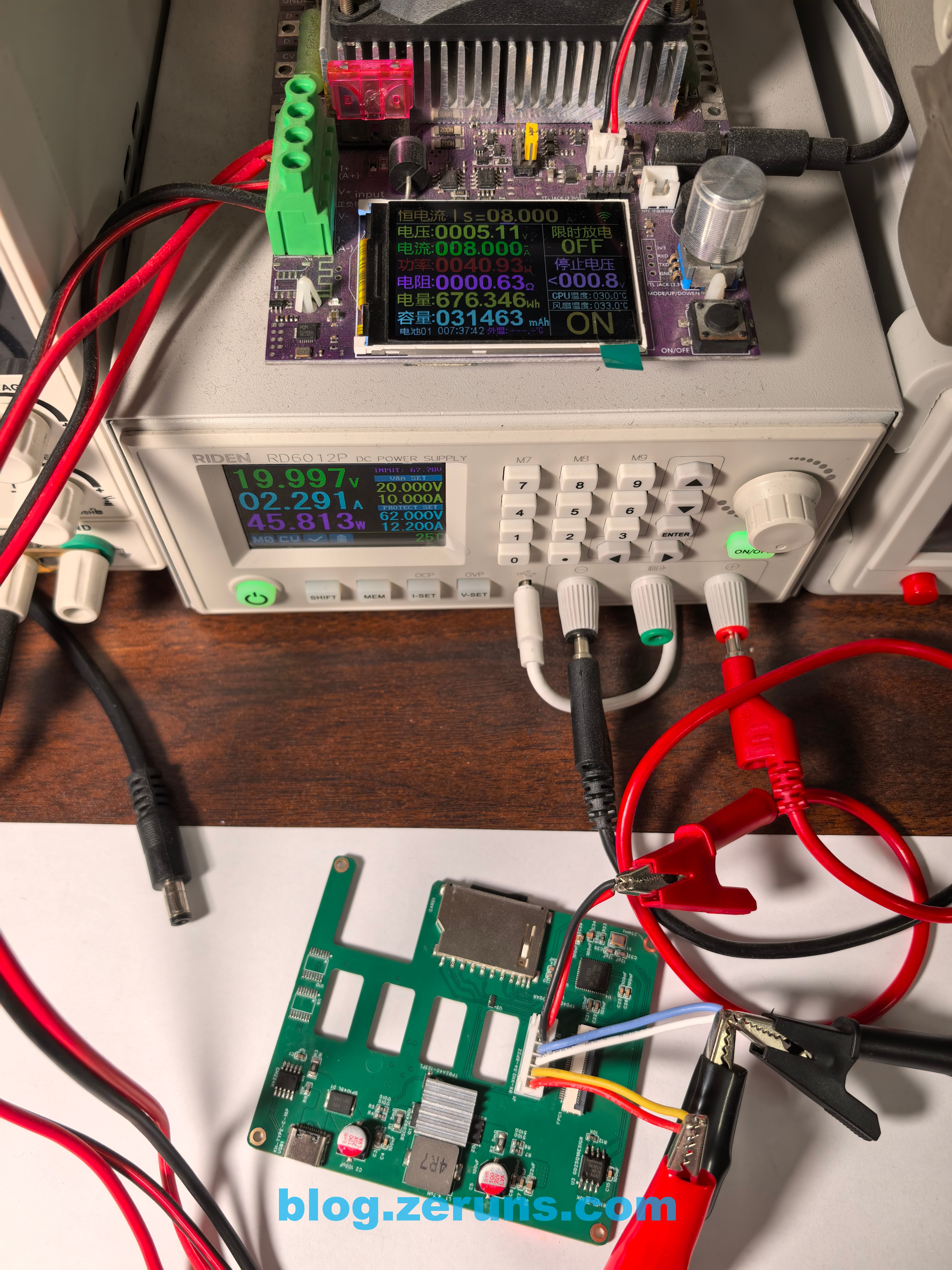
Power Conversion Efficiency
| Input Voltage(V) | Input Current(A) | Input Power(W) | Output Voltage(V) | Output Current(A) | Output Power(W) | Efficiency(%) |
|---|---|---|---|---|---|---|
| 19.997 | 2.291 | 45.81 | 5.11 | 8 | 40.88 | 89.23% |
| 19.998 | 1.122 | 22.44 | 5.15 | 3.999 | 20.59 | 91.79% |
| 19.998 | 0.569 | 11.38 | 5.18 | 2.002 | 10.37 | 91.14% |
| 4 | 2.839 | 11.36 | 5.2 | 2 | 10.40 | 91.58% |
| 4 | 8.063 | 32.25 | 5.17 | 5 | 25.85 | 80.15% |
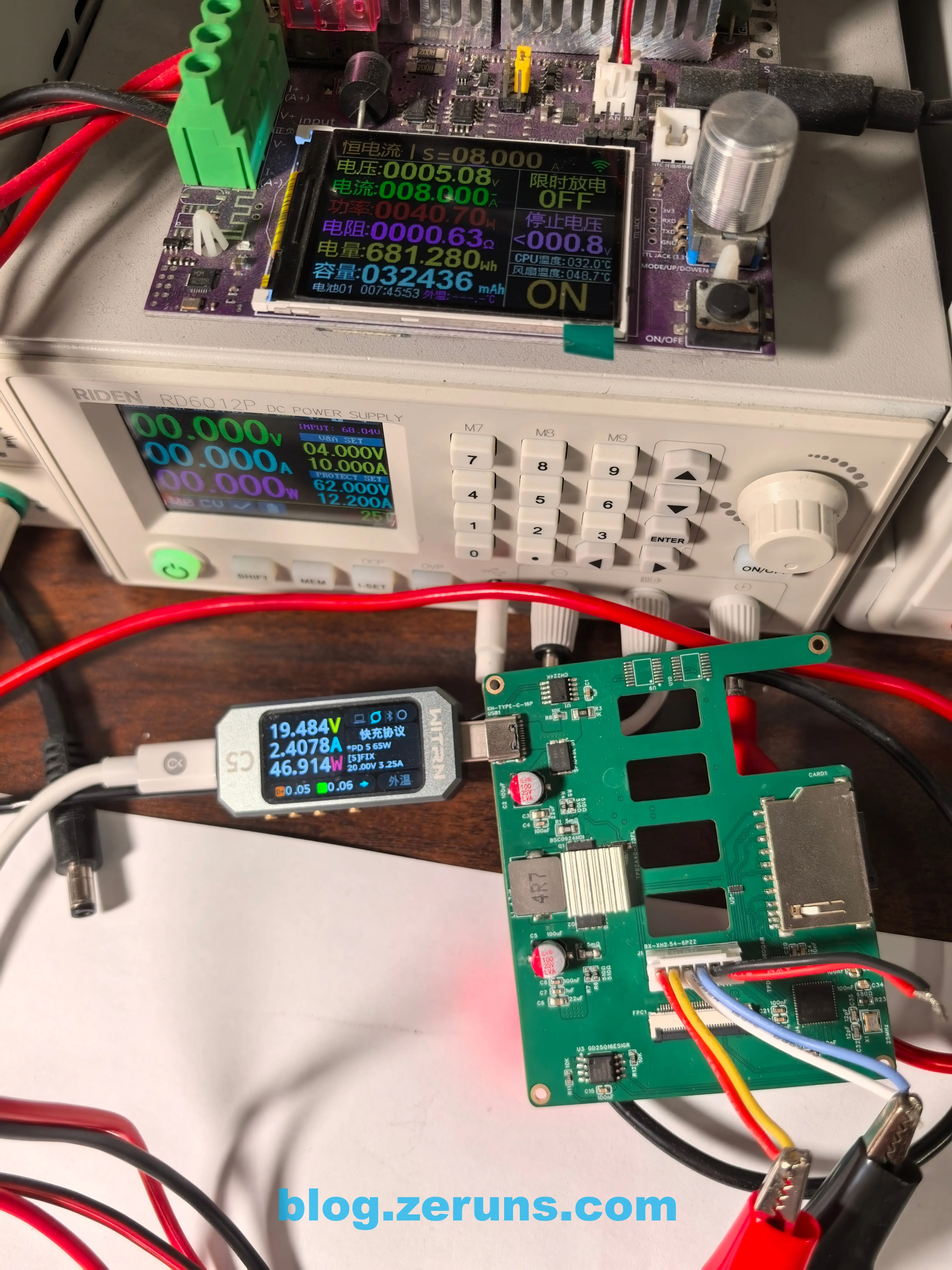
PD Fast Charging Detection Test
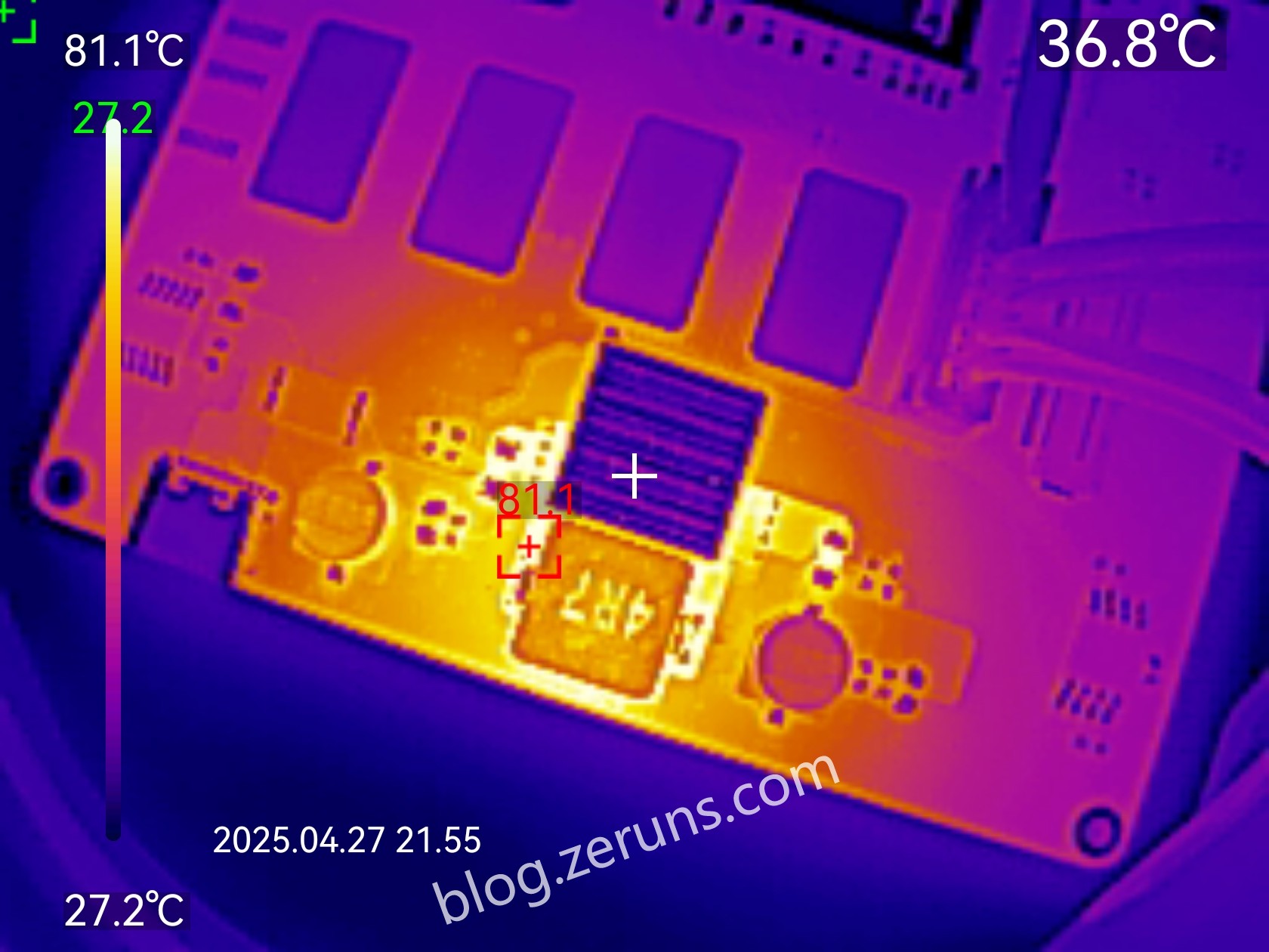
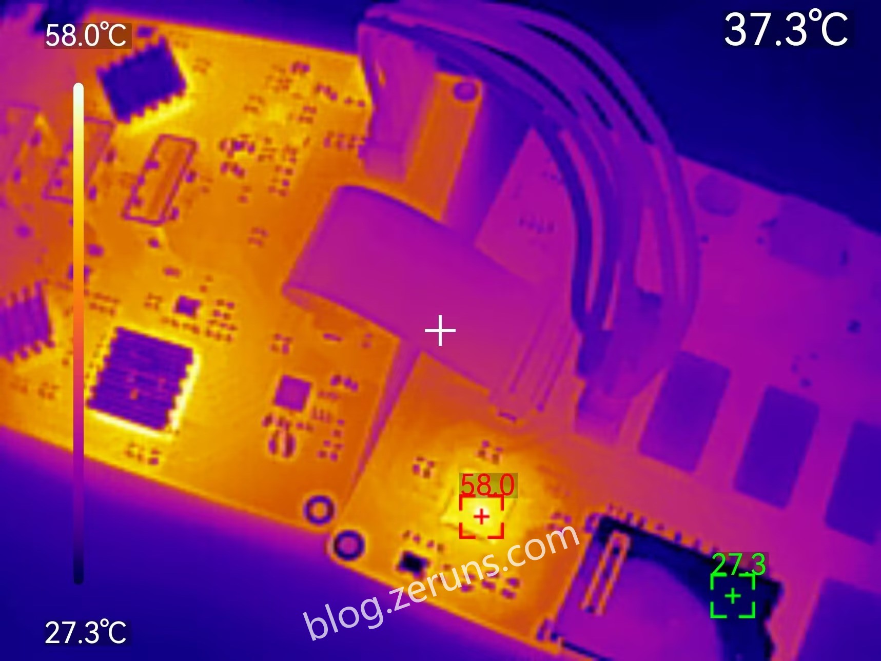
Thermal Imaging
-
5V power circuit at 8A output: MOSFET ~81°C (ambient ~27°C)
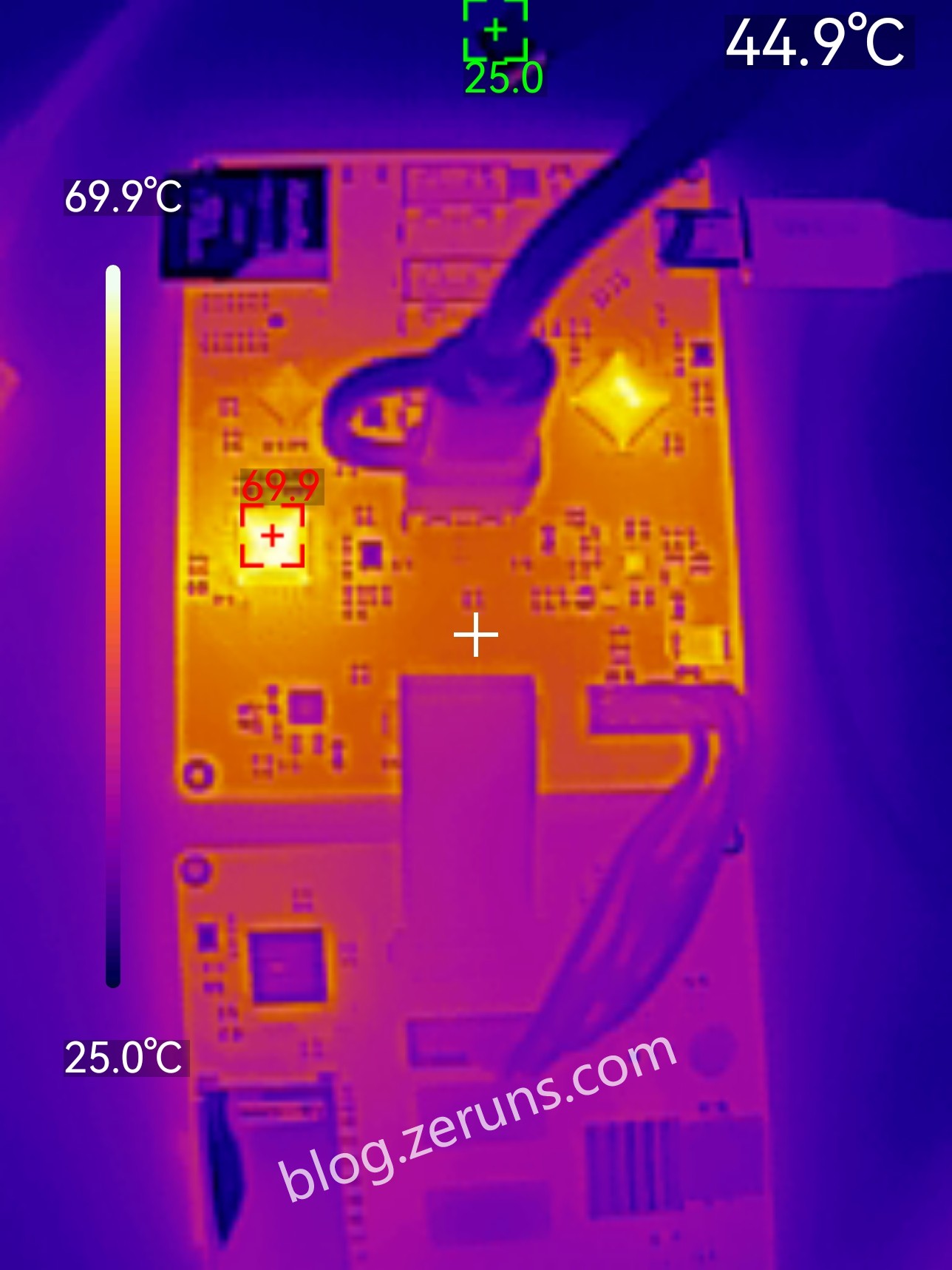
-
VL822 chip at full load: ~70°C (ambient ~25°C)
-
GL3224 chip at full load: ~58°C (ambient ~27°C)
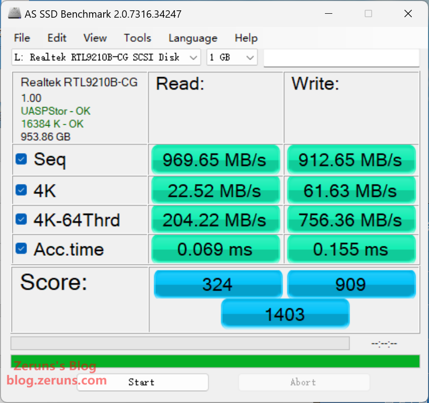
USB Interface Speed Test
Connecting the dock to a computer’s USB@10Gbps port and testing an RTL9210B-based external SSD via AS SSD Benchmark: Read 969.65MB/s, Write 912.65MB/s.
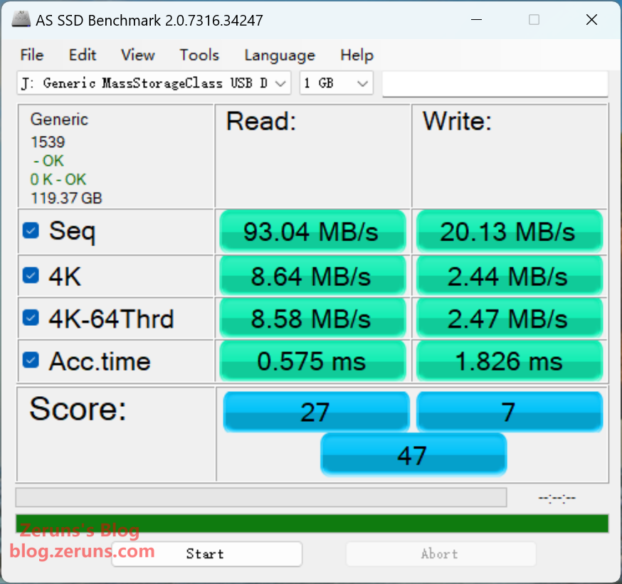
TF/SD Card Reader Speed Test
Using a Samsung EVO Plus TF card: Read 93.04MB/s, Write 20.13MB/s.
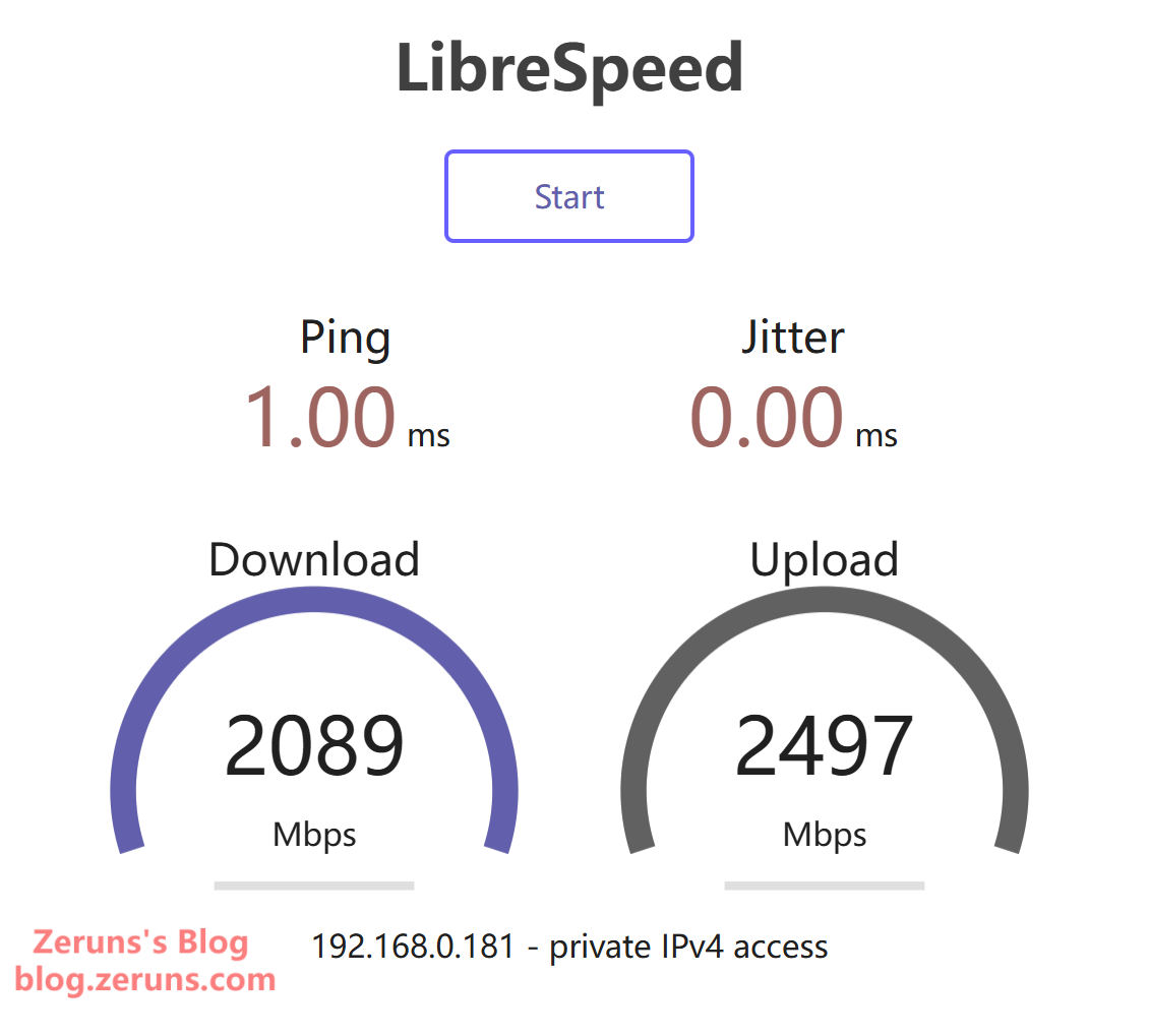
2.5G Ethernet Speed Test
Internal network speed test server shows: Download 2089Mbps, Upload 2497Mbps.
Replication Notes
- The enclosure is 3D-printed. 3D model files available in the download section at the end of the article.
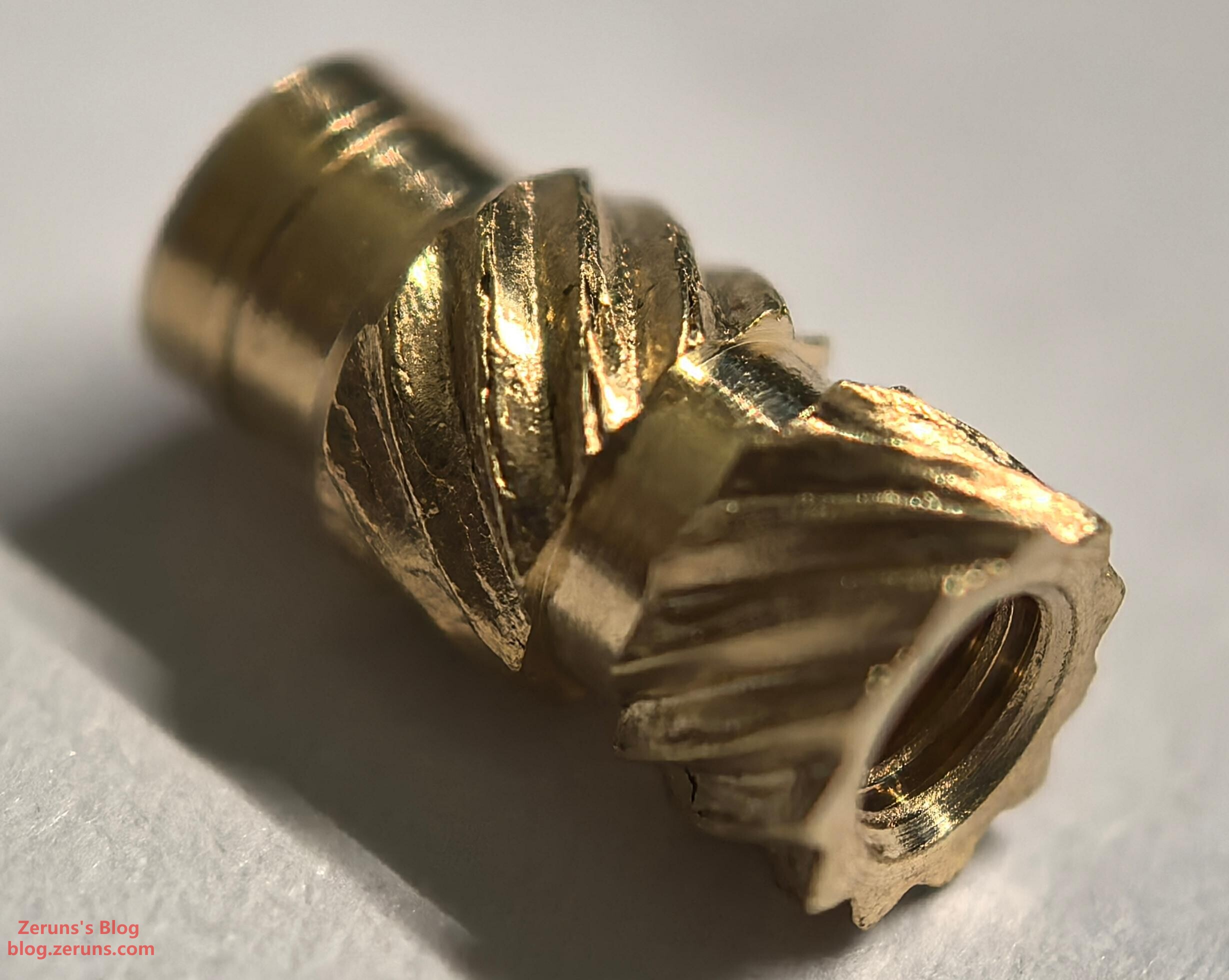
- Enclosure screw holes require M2.5 heat-set nuts (installed using a soldering iron).
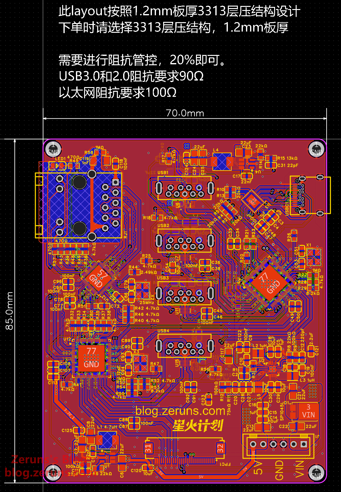
- When ordering PCBs, select JLC04121H-3313 stack-up, board thickness 1.2mm, and require impedance matching.
- Some systems may experience reduced Ethernet speeds. Install drivers from
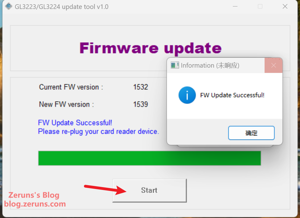
绿联USB有线网卡-RTL芯片-全系统_UGREEN_EthernetAdapter Driver_V1.01.zip(available in the download section). - Card reader speed issues may require firmware updates. Use the tool in
GL3224 update tool v1.0(factory firmware v1532, latest v1539). Flash chip can be omitted if no update needed. - Both 30-pin FPC and 6-pin XH2.54 cables must be reverse-assembled.
M2.5×8×4 Heat-set Nuts
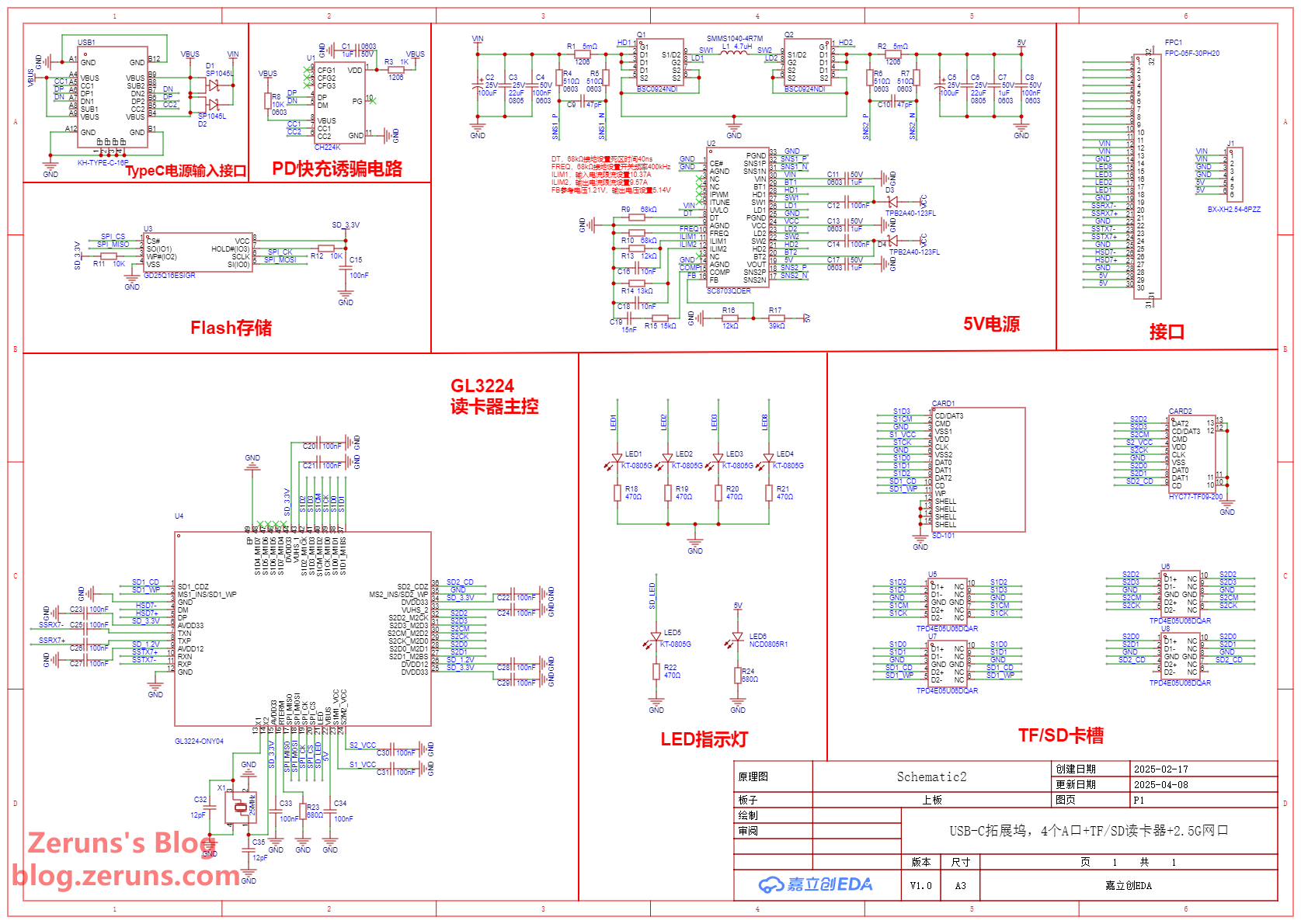
Schematics
Upper Board
Lower Board
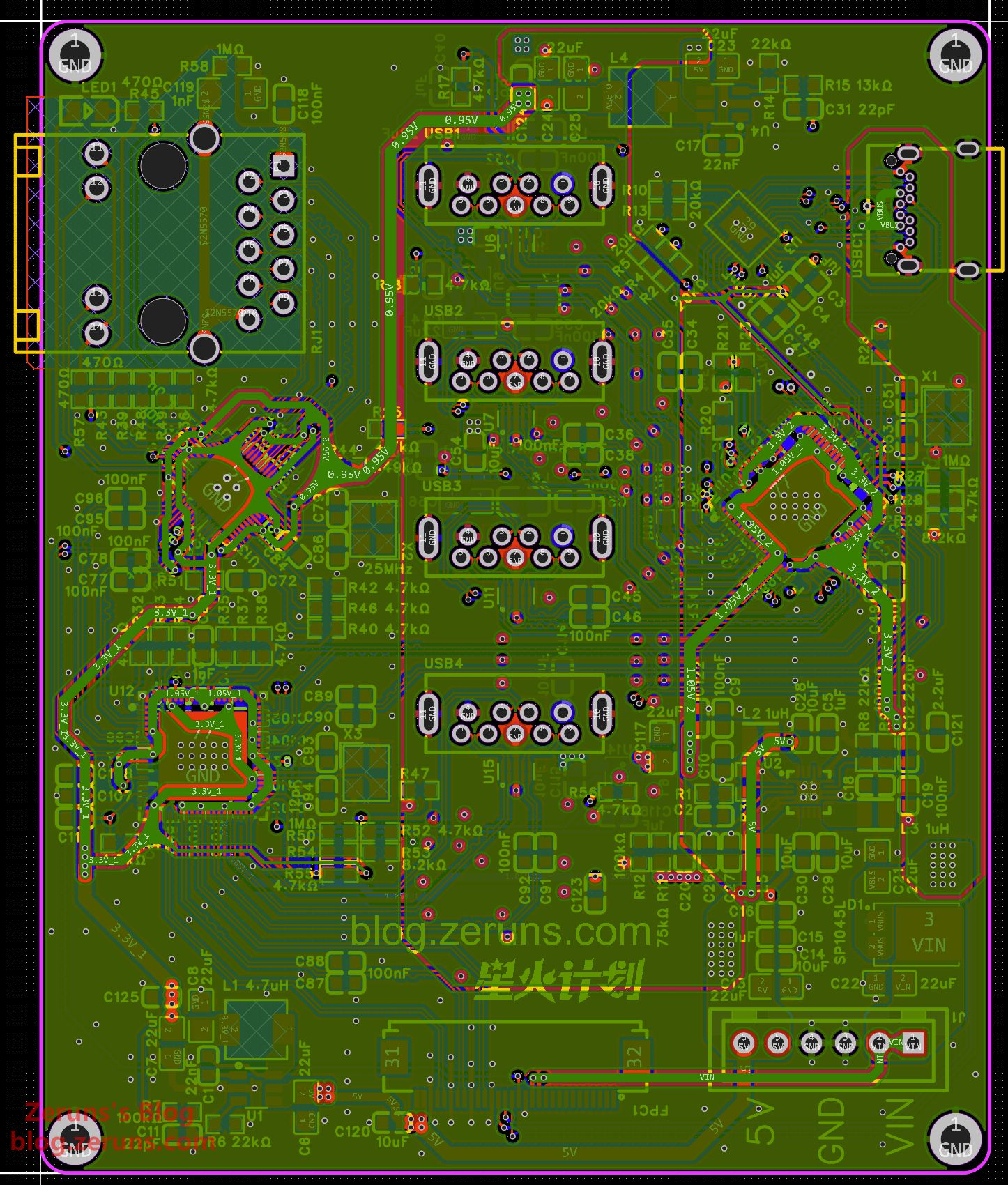
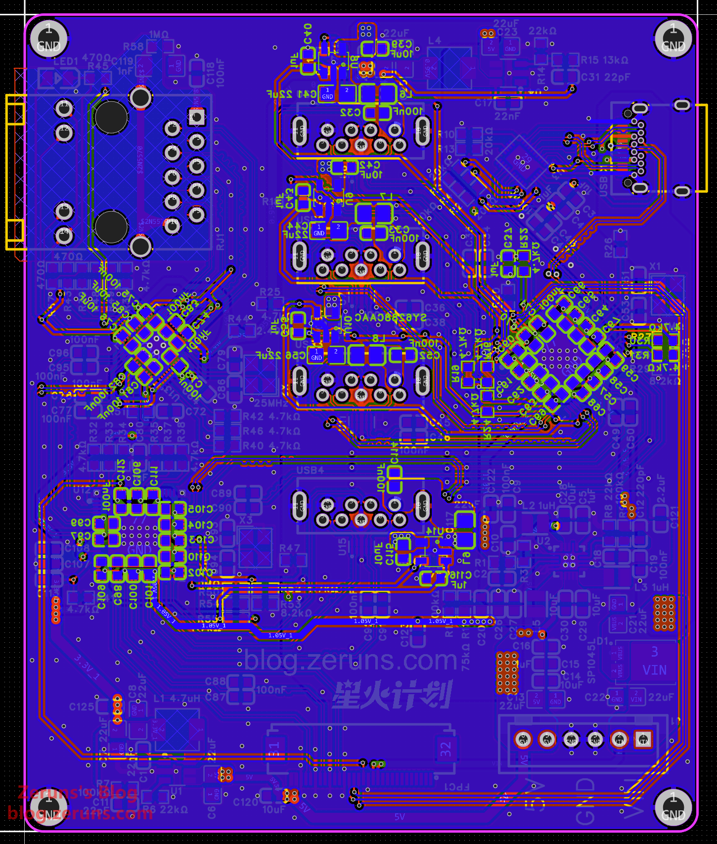
PCB Layouts
Upper Board
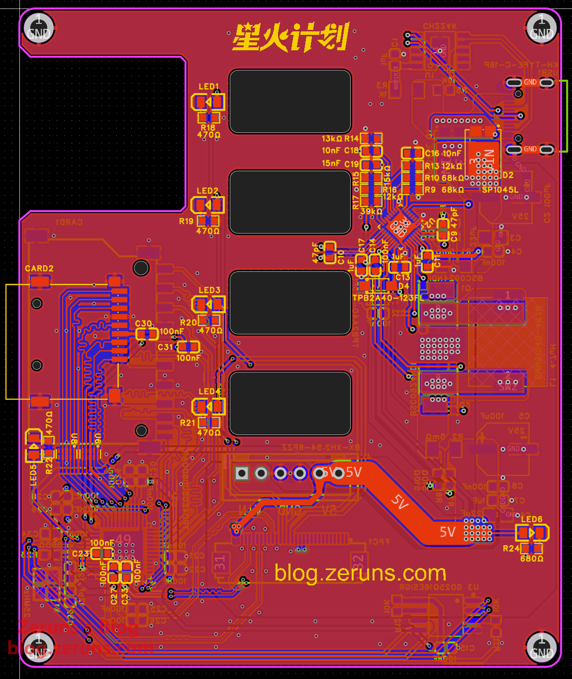
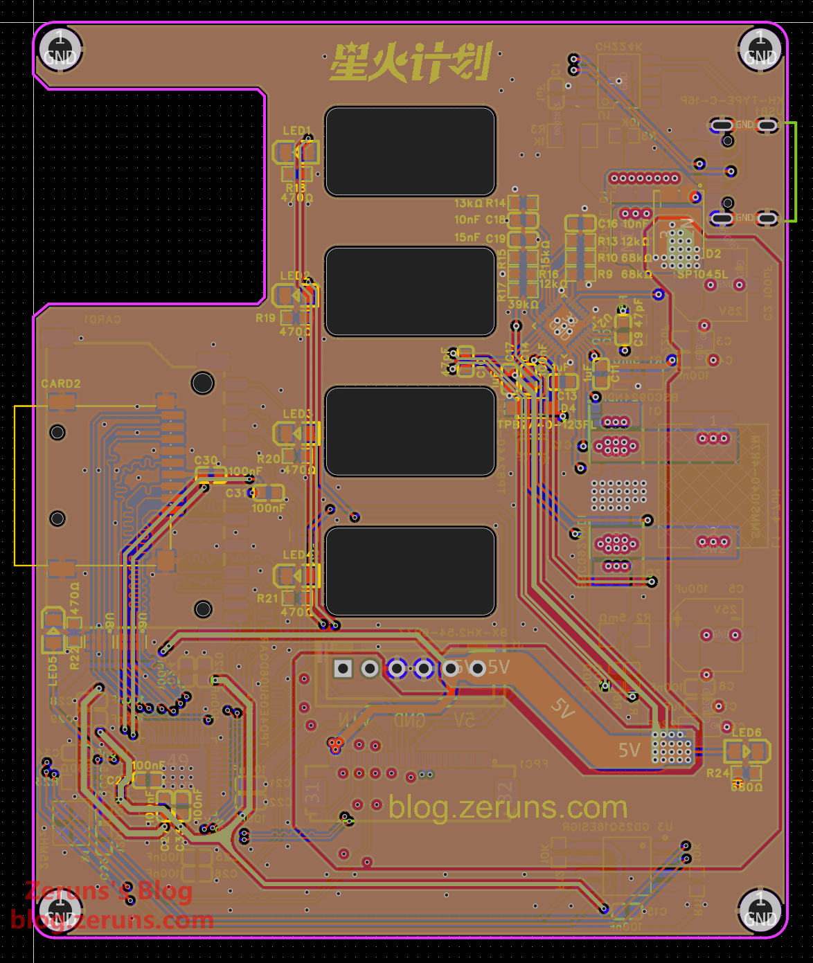
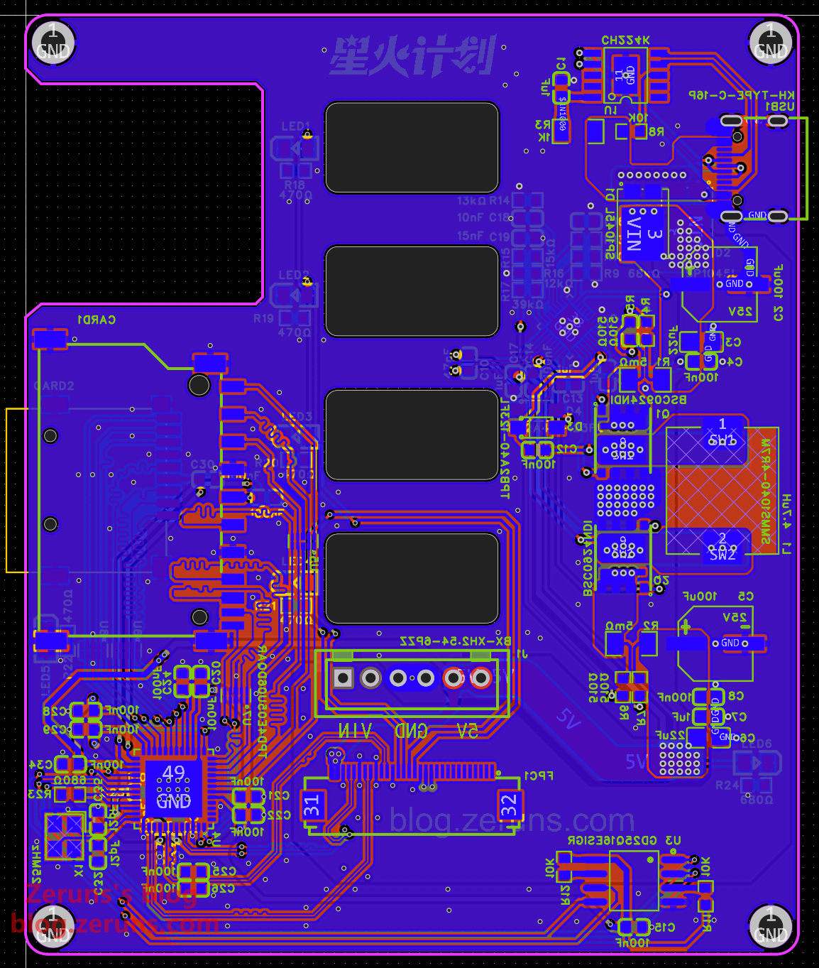
Lower Board
Component Purchase Links
Most components used in this project are available here:
-
0603 Resistor
-
Open-sourced a three-phase power meter for convenient home electricity monitoring: https://blog.zeruns.com/archives/771.html
-
STM32F407-based LVGL project template (MSP3526 display), including FreeRTOS and bare-metal versions: https://blog.zeruns.com/archives/788.html
-
Open-source synchronous rectification Buck-Boost digital power supply based on STM32: https://blog.zeruns.com/archives/791.html
-
LM25118 automatic step-up/down adjustable DCDC power module: https://blog.zeruns.com/archives/727.html
-
EG1164 high-power synchronous rectification boost module open-source (up to 97% efficiency): https://blog.zeruns.com/archives/730.html
-
4G environmental monitoring node based on Heltec Air700E (temperature, humidity, pressure data) via MQTT to Alibaba Cloud IoT platform: https://blog.zeruns.com/archives/747.html
-
Open-source intelligent electronic load based on CH32V307 (embedded competition project): https://blog.zeruns.com/archives/785.html
-
EG1151 high-power synchronous rectification adjustable step-up/down power module (supports Type-C PD fast charging input): https://blog.zeruns.com/archives/794.html
-
Open-source 140W+65W step-up/down PD3.1 fast charging module (2C+1A ports), IP6557+IP6538, 205W desktop charger: https://blog.zeruns.com/archives/801.html
Recommended Reading
- Recommended cost-effective and affordable VPS/cloud servers: https://blog.zeruns.com/archives/383.html
- Minecraft server setup tutorial: https://blog.zeruns.com/tag/mc/
- One-click deployment of Halo blog with 1Panel dashboard (enterprise website/personal blog tutorial): https://blog.zeruns.com/archives/858.html
- Introduction to 4 user-friendly server panels for one-click deployment of MC modpacks, Palworld, 7 Days to Die, CSGO servers: https://blog.zeruns.com/archives/808.html
- Ultra7-265K and Gigabyte Z890M AORUS ELITE WIFI7 motherboard unboxing review: https://blog.zeruns.com/archives/863.html
- Flarum forum setup tutorial for beginners: https://blog.zeruns.com/archives/866.html
English Version of the Article: https://blog.zeruns.top/archives/53.html