Ruideng RD6012P Constant Voltage and Constant Current CNC DC Adjustable Power Supply unboxing and review. Conducted tests including no-load power consumption and efficiency, constant current output accuracy and current readback accuracy, constant voltage output accuracy and voltage readback accuracy, output ripple. Also included a brief analysis of the chips used (only those visible on the back, without disassembling the unit).
Introduction
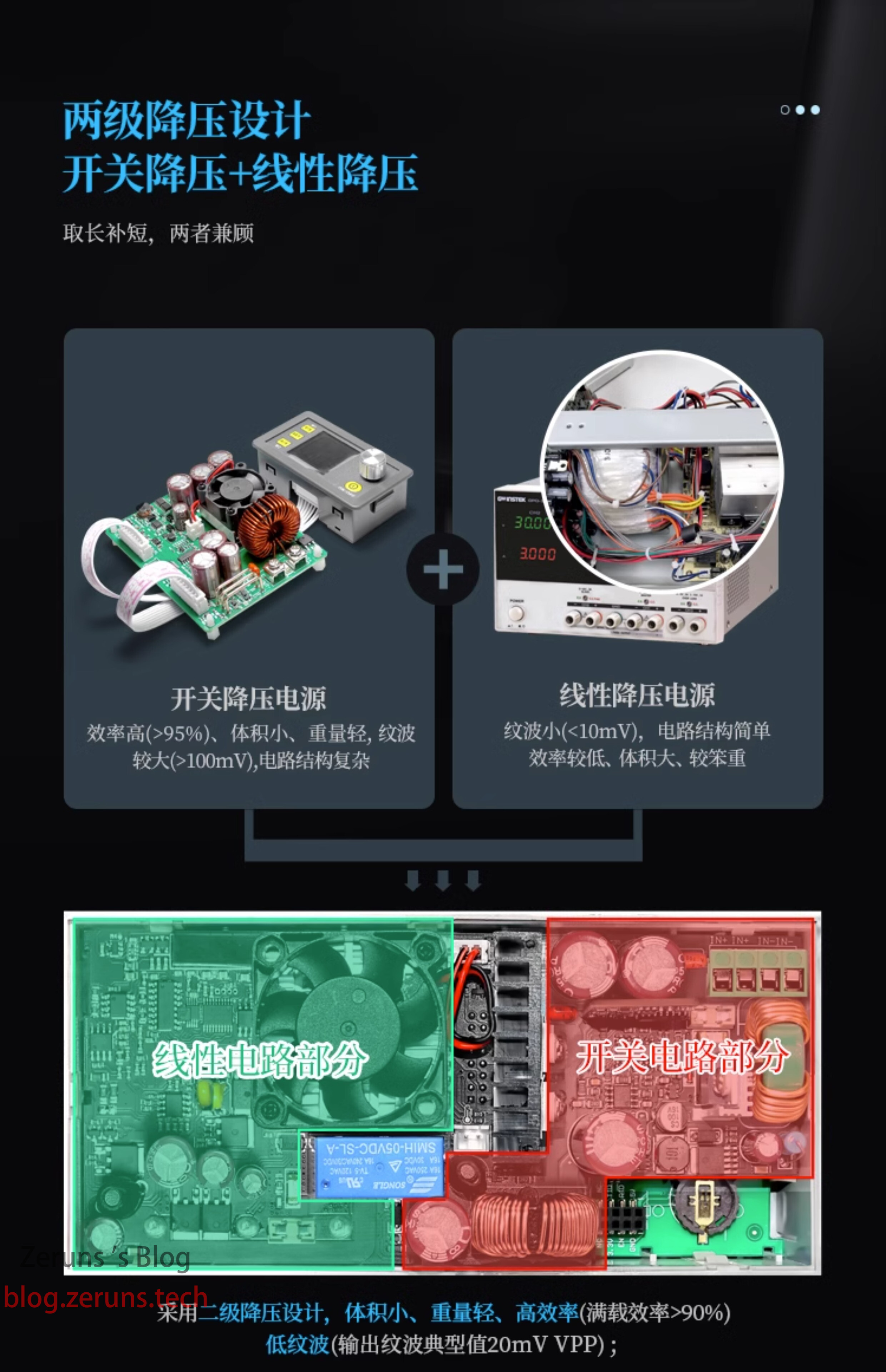
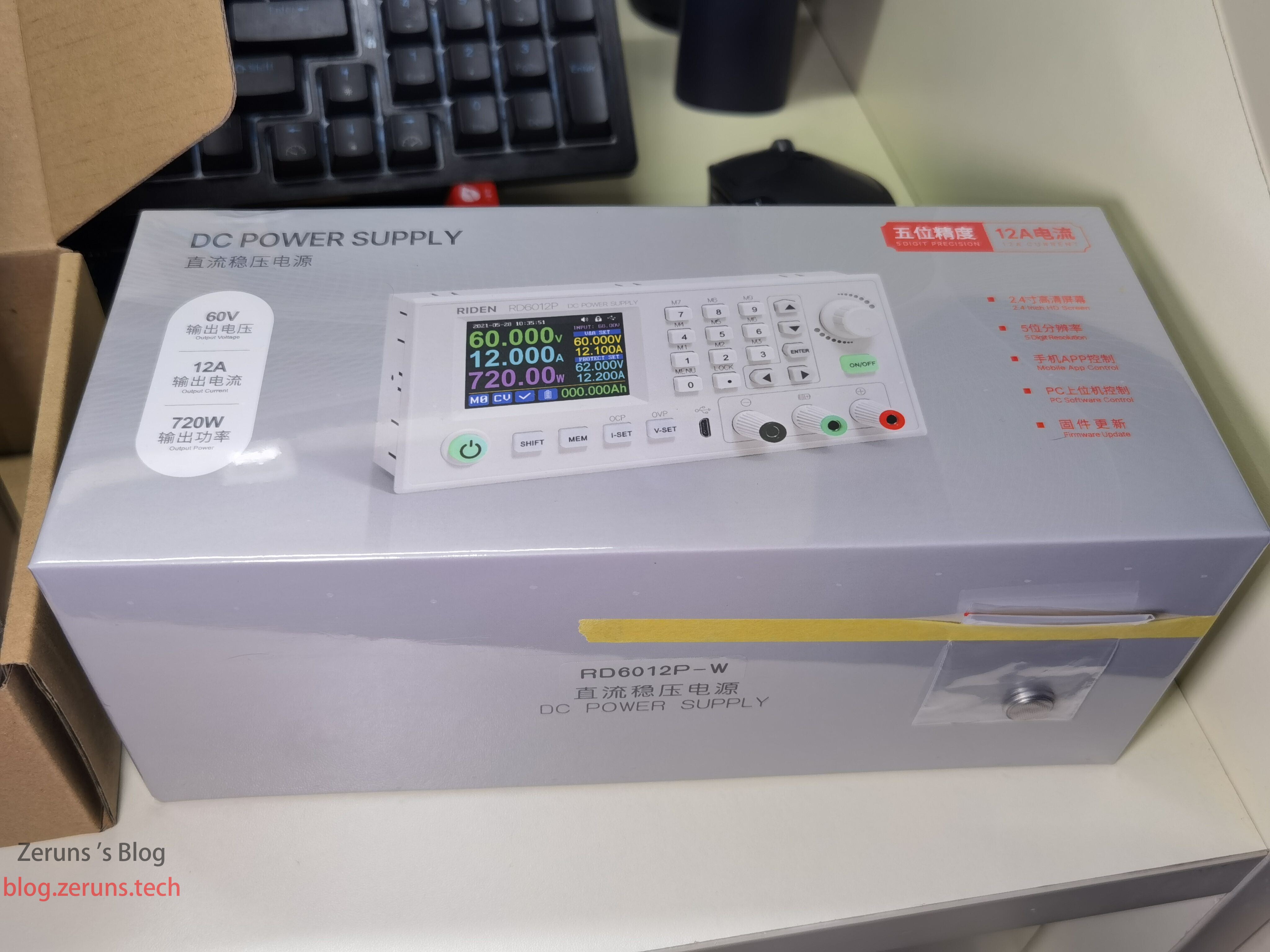
The main features of this power supply include a maximum output of 60V, 12A, 720W, 5-digit resolution, and a two-stage buck design combining switching power supply + linear buck (the linear stage follows the switching stage: the switching power supply first reduces the voltage to slightly above the target voltage, then the digitally-controlled linear regulator further steps it down to the exact target voltage, achieving low ripple—this is my understanding). It supports constant voltage (CV) and constant current (CC) modes, battery charging functions (over-temperature protection, constant current charging, automatic output shutdown when charging current drops to the set value), and programmable output via USB or WiFi connectivity.
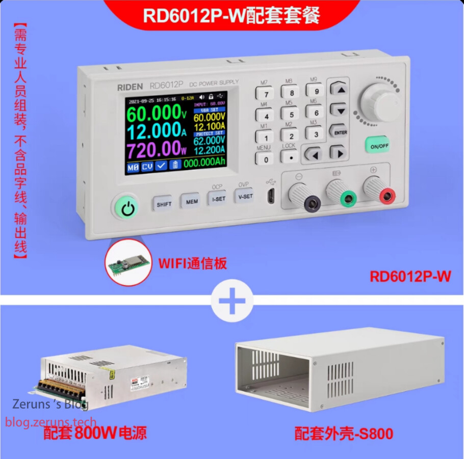
I’ve wanted this unit for a while and finally purchased it during the Double Eleven sale. I bought the complete kit: RD6012P-W + 68V pre-stage switching power supply + enclosure, for 778 RMB—over 100 RMB cheaper than usual. For an extra 100 RMB, you can get it pre-assembled.
Download CNC power supply metal enclosure (S800) assembly manual: https://url.zeruns.com/t53x7
Download RD6012P manual: https://url.zeruns.com/7p8CD
Electronics/Microcontroller Technology Discussion Group: 2169025065
Purchase link: https://s.click.taobao.com/iILxs5u
Product Specifications
| Model | RD6012P-W |
|---|---|
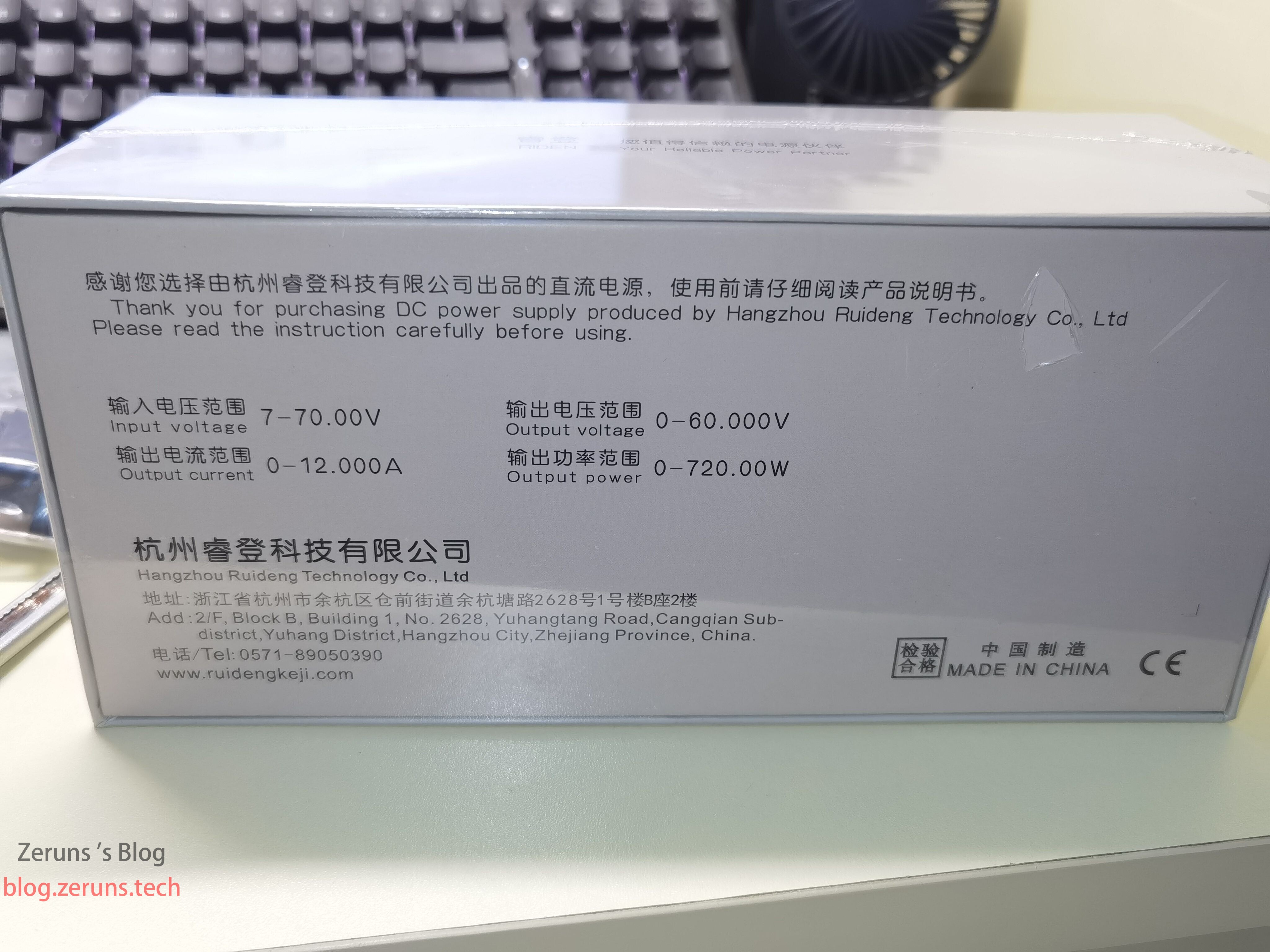
| Input Voltage Range | 7-70.00V |
| Output Voltage Range | 0-60.000V |
| Output Current Range | 0-12.000A |
| Output Power Range | 0-720.00W |
| Input Voltage Resolution | 0.01V |
| Output Voltage Setting/Measurement Resolution | 0.001V |
| Current Setting Resolution | 0.0001A (6A range) / 0.001A (12A range) |
| Battery Voltage Resolution | 0.01V |
| Input Voltage Accuracy | ±(1% + 5 digits) |
| Output Voltage Accuracy | ±(0.5% + 4 digits) |
| Output Current Accuracy | ±(1% + 6 digits) |
| Battery Voltage Accuracy | ±(0.5% + 3 digits) |
| Auto-shutdown Current in Charging | Adjustable |
| Typical Output Ripple | 20mV Vpp ① |
| Operating Temperature Range | -10℃~40℃ |
| External Temp Sensor Range | -10℃~100℃ / 0°F~200°F |
| External Temp Sensor Error | ±3℃ / +6°F |
| CV Mode Response Time | 2ms (0.1A–5A load) |
| CV Load Regulation | ±(0.1% + 2 digits) |
| CC Load Regulation | ±(0.1% + 3 digits) |
| Capacity Measurement Range | 0–9999.99Ah |
| Energy Measurement Range | 0–9999.99Wh |
| Capacity/Energy Measurement Error | ±2% |
| Max Output Voltage | (Input Voltage ÷ 1.1) – 2 ② |
| Fan Start Condition | Output Current > 4A or System Temp > 50℃ |
| Fan Stop Condition | Output Current < 3.9A and System Temp < 50℃ |
| Over-Temperature Protection | System Temp > 80℃ |
| Screen Brightness Levels | 0–5 (6 levels) |
| Display | 2.4-inch color LCD |
| Weight with Packaging | ~0.66kg |
| Dimensions | 167×81×65mm |
| USB Communication Support | Yes |
| WiFi Communication Support | Yes |
① Ripple measurement method: measured at output terminals, with a 0.1μF capacitor connected, oscilloscope set to ×1, AC coupling, 20MHz bandwidth limit, using high-power resistive load.
② Example: with 24V input, maximum output voltage is 19.8V.
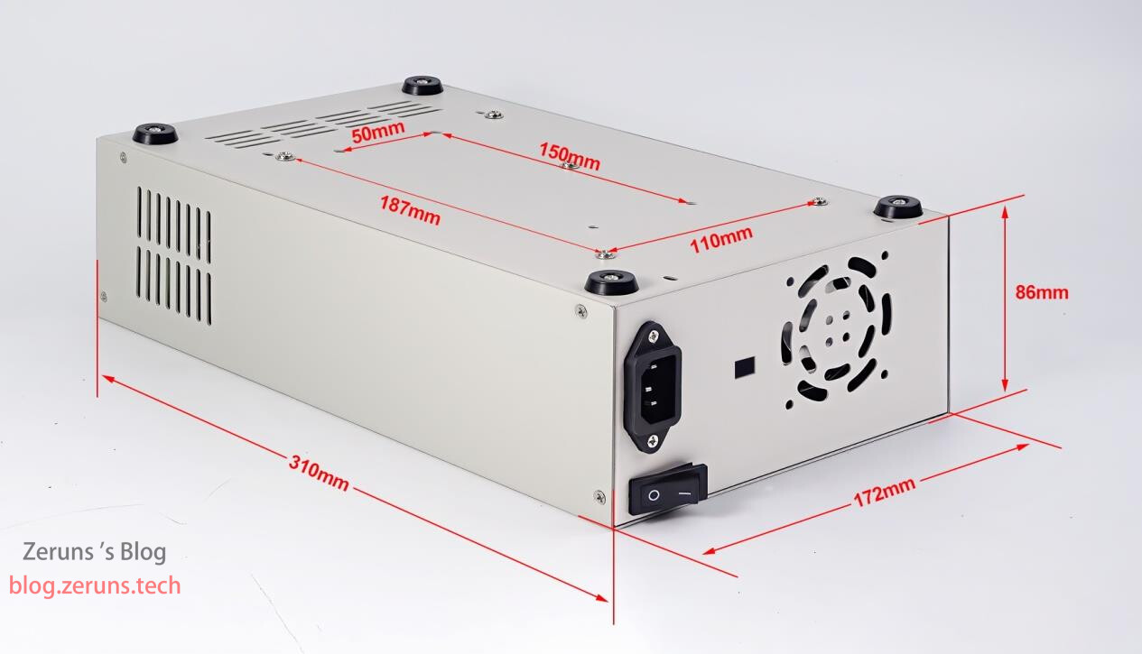
Enclosure dimensions: 310×172×86mm (L×W×H)
Unboxing
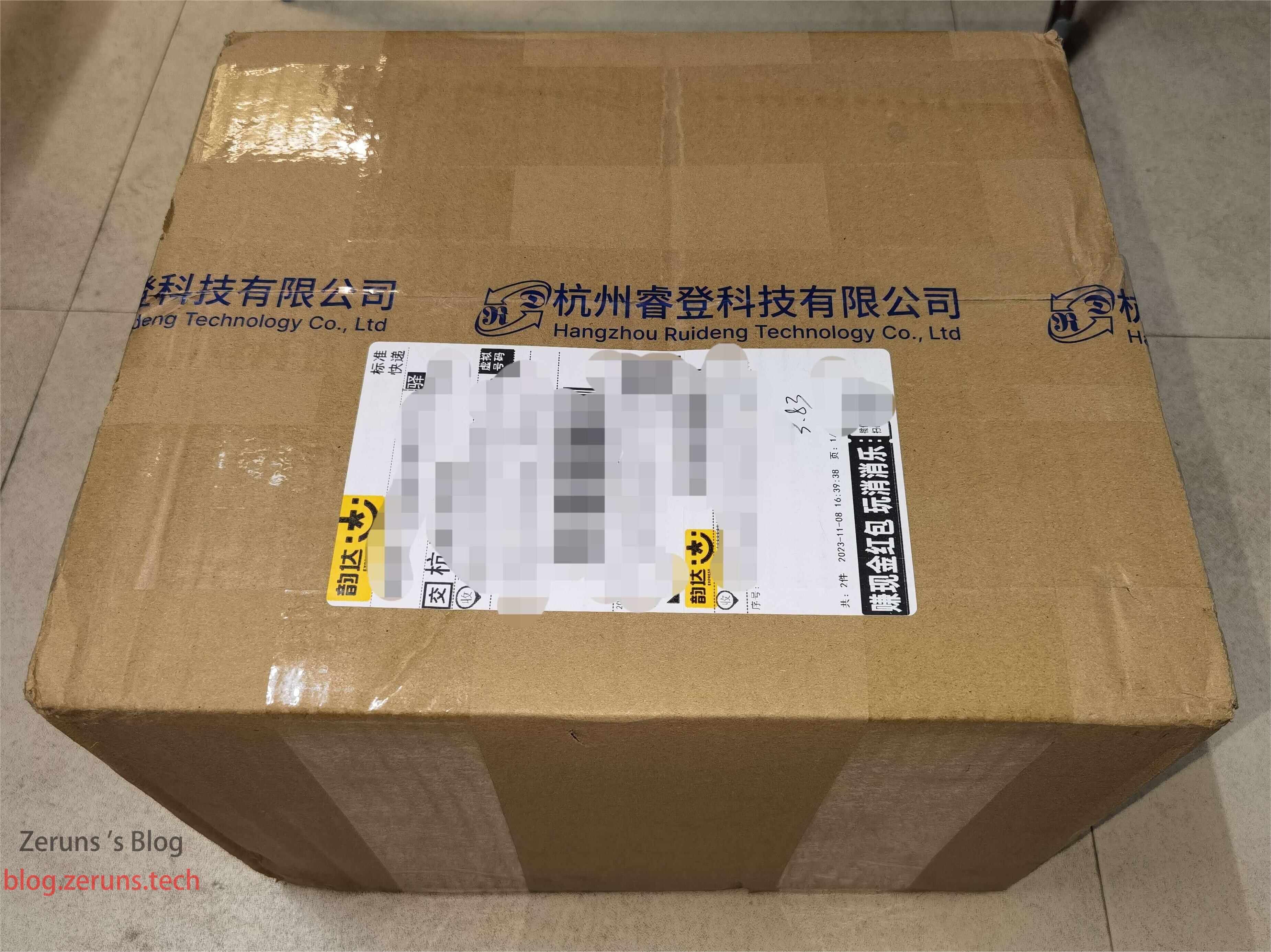
Shipping box:
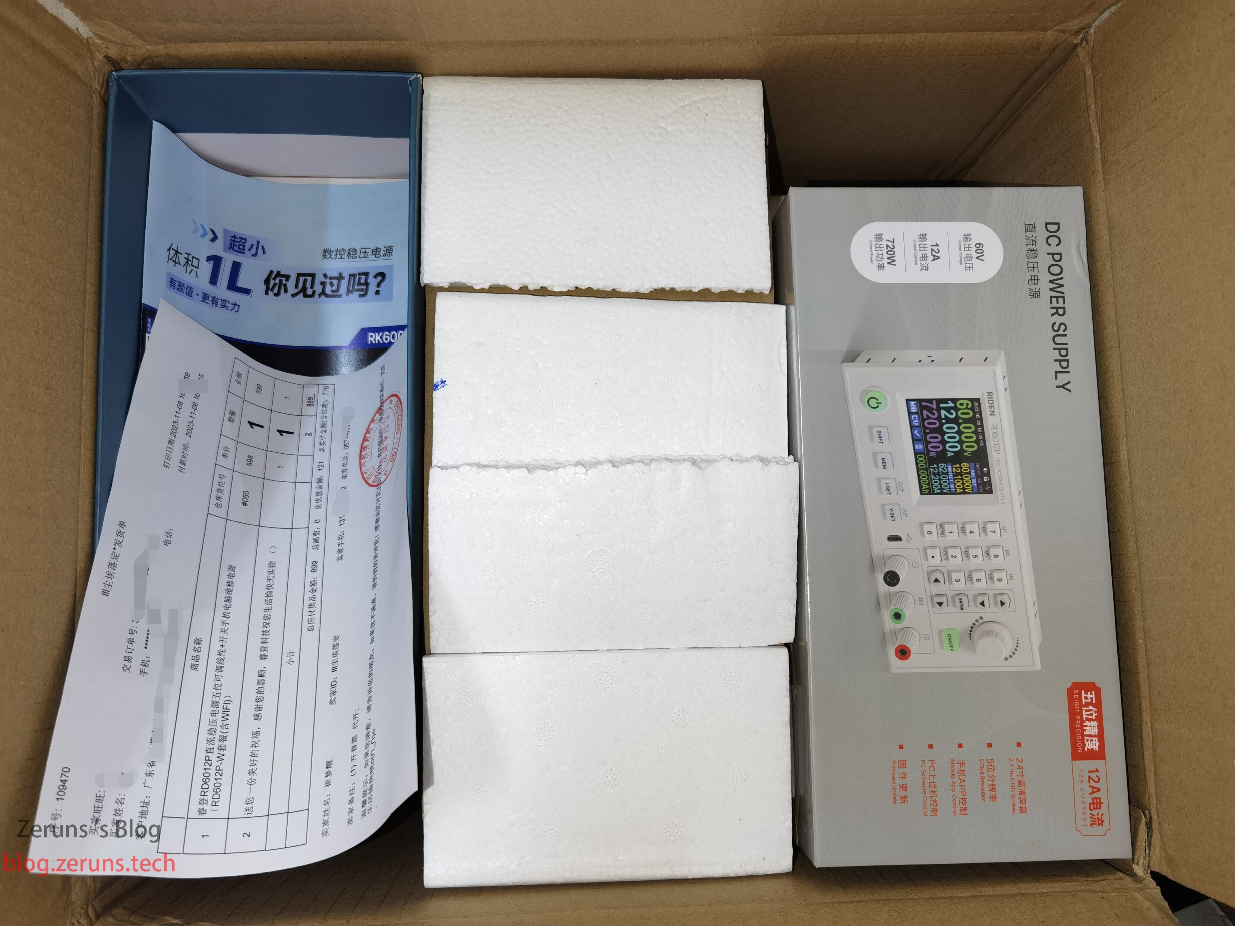
Inside the box: on the left are product brochures and invoice, in the middle is the pre-stage switching power supply (converts 220V AC to 68V DC), on the right is the RD6012P-W CNC adjustable power supply (a CV/CC DC-DC converter that steps down the 68V input from the pre-stage supply to the desired output voltage).
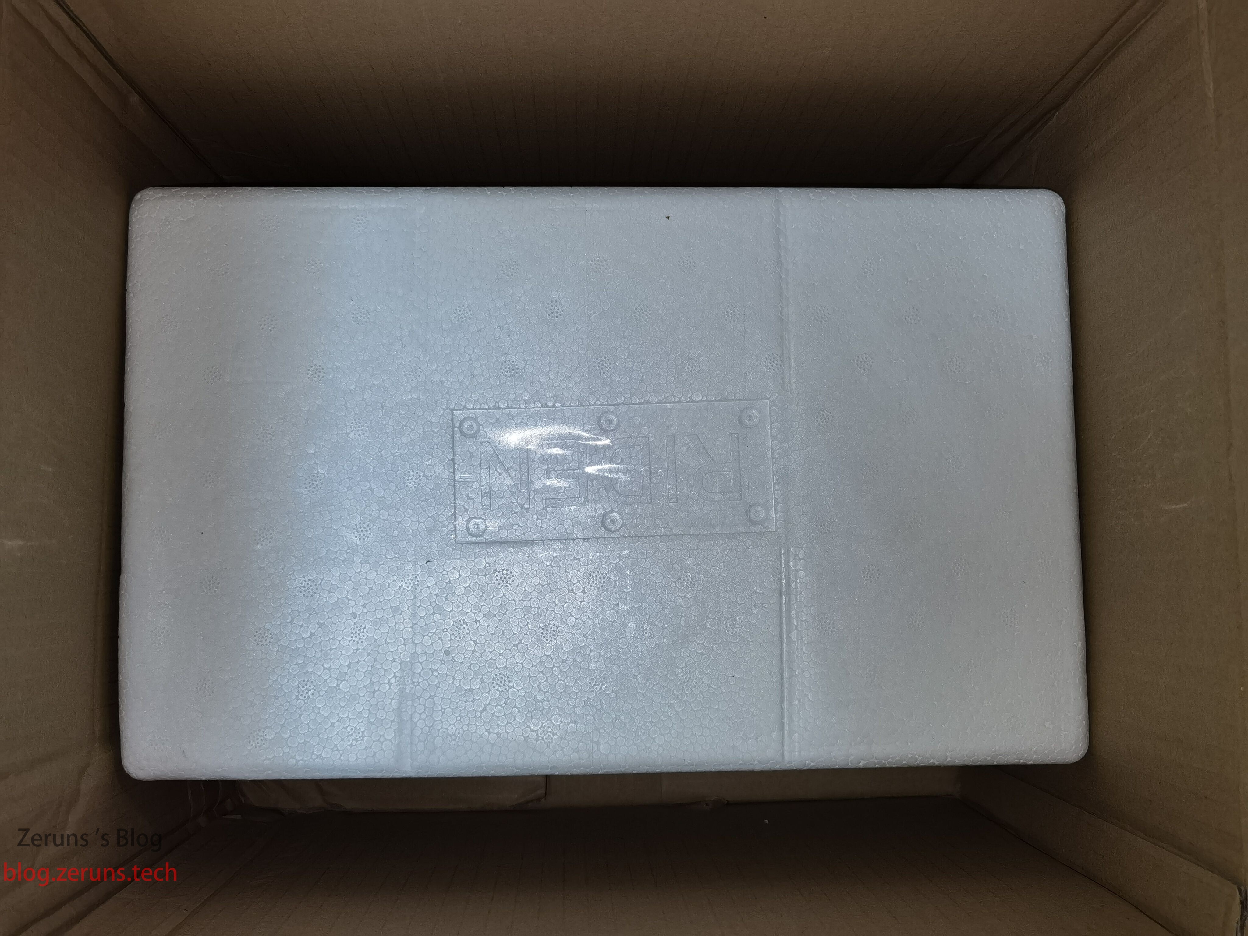
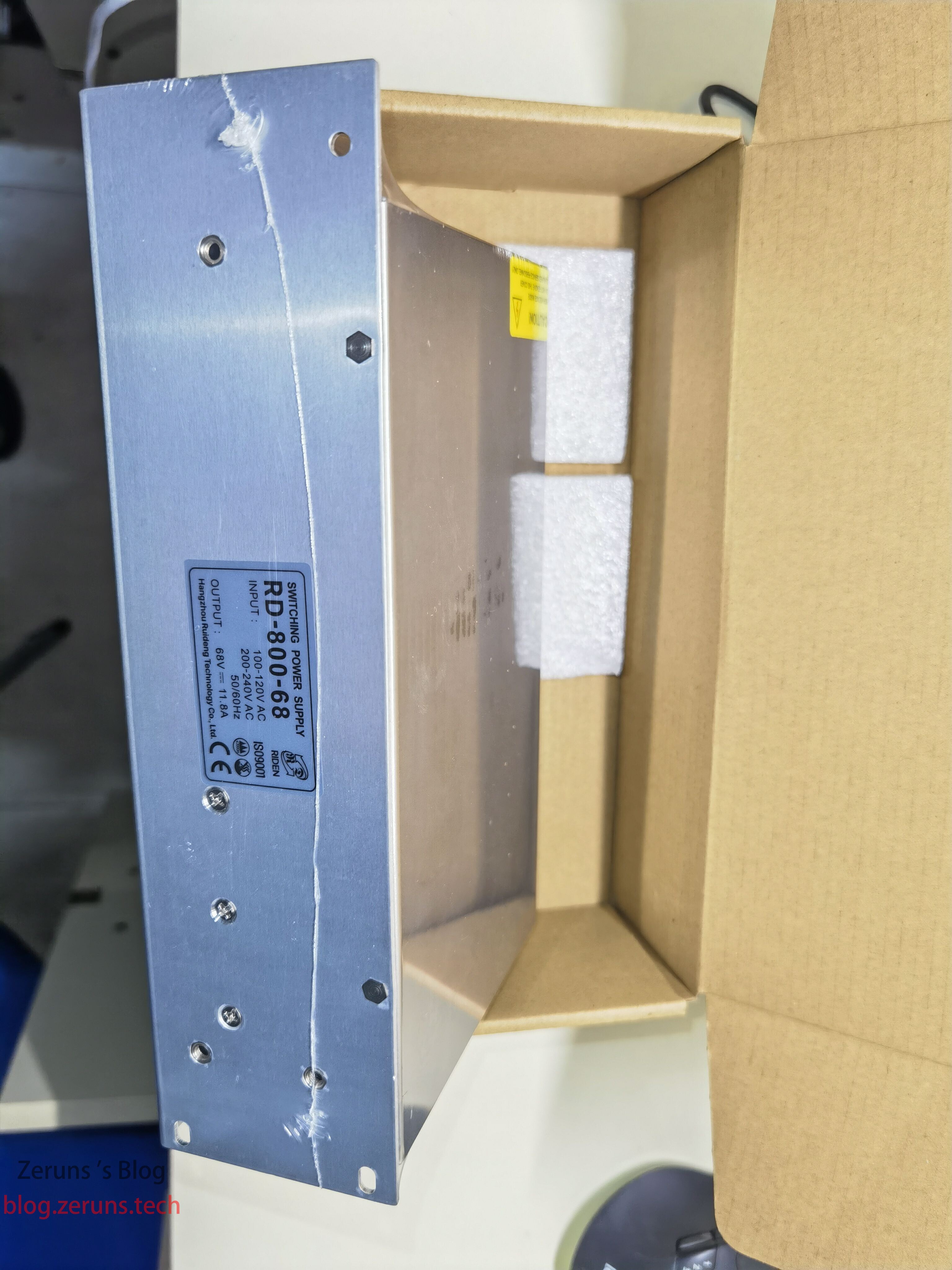
At the bottom of the box is the enclosure, packed in foam.
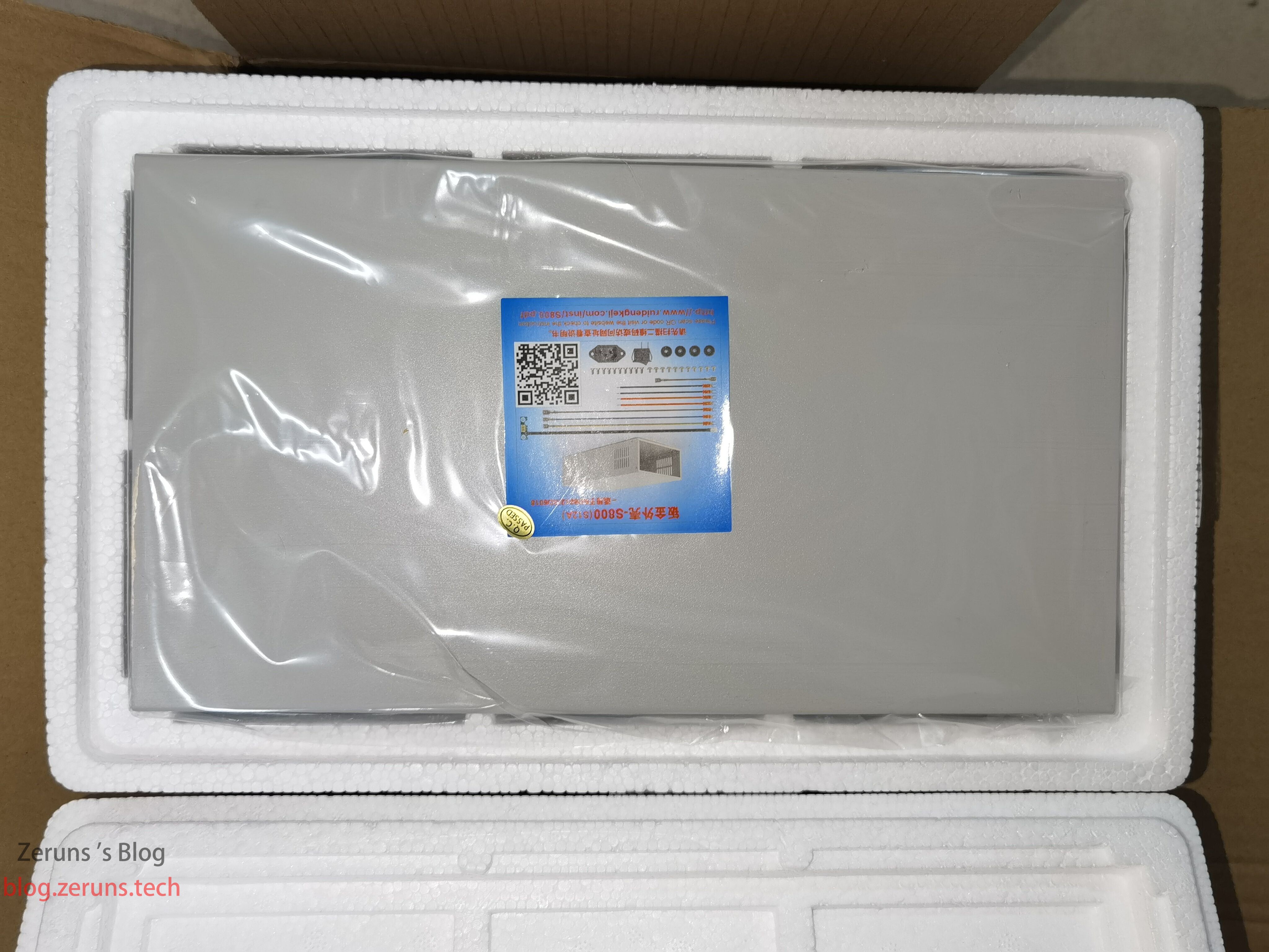
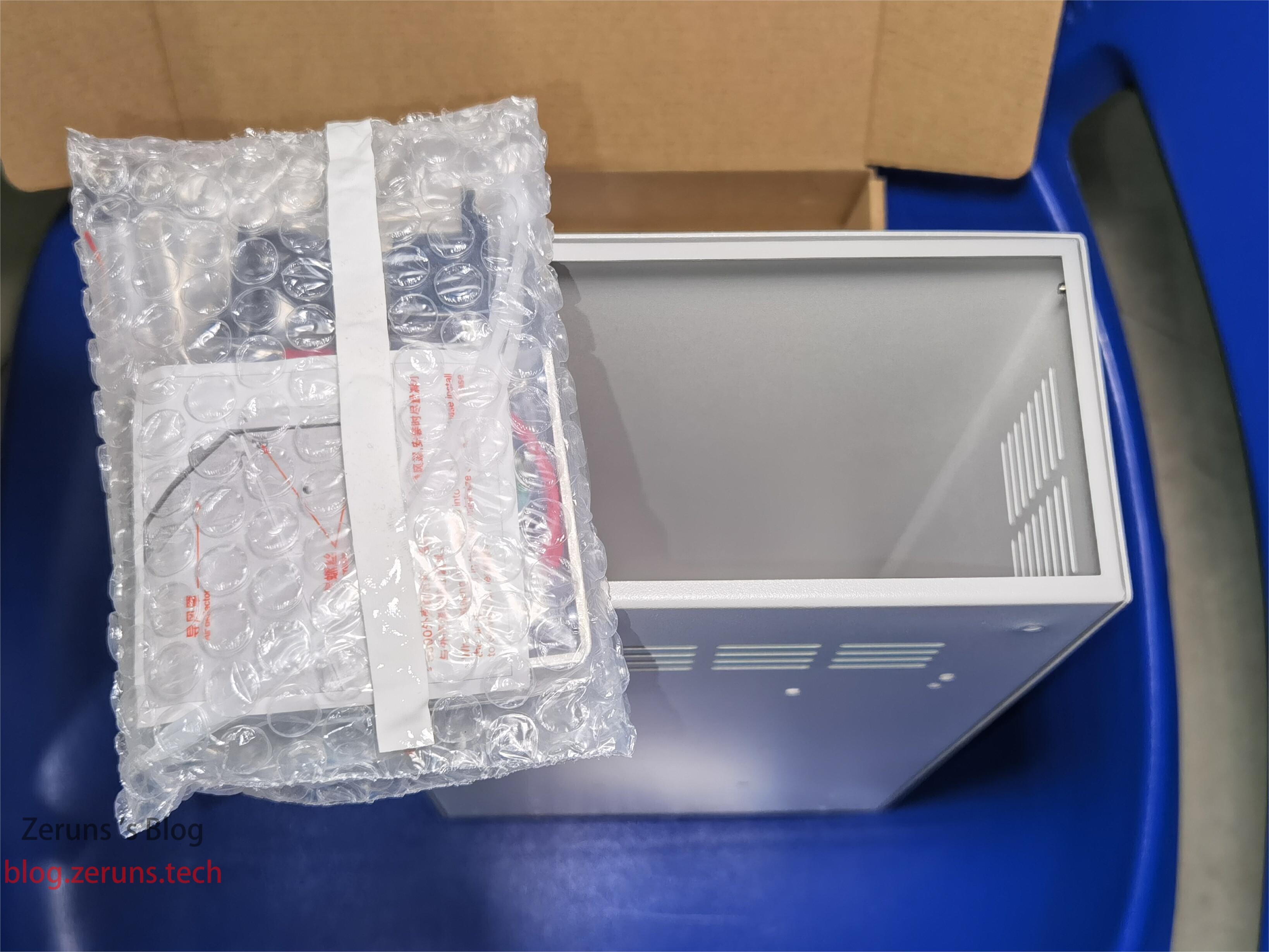
The enclosure, which also contains a bag of accessories, screws, and connecting cables.
Side view of the pre-stage power supply, model RD-800-68, input 100–120VAC / 200–240VAC, output 68V 11.8A, max power 800W.
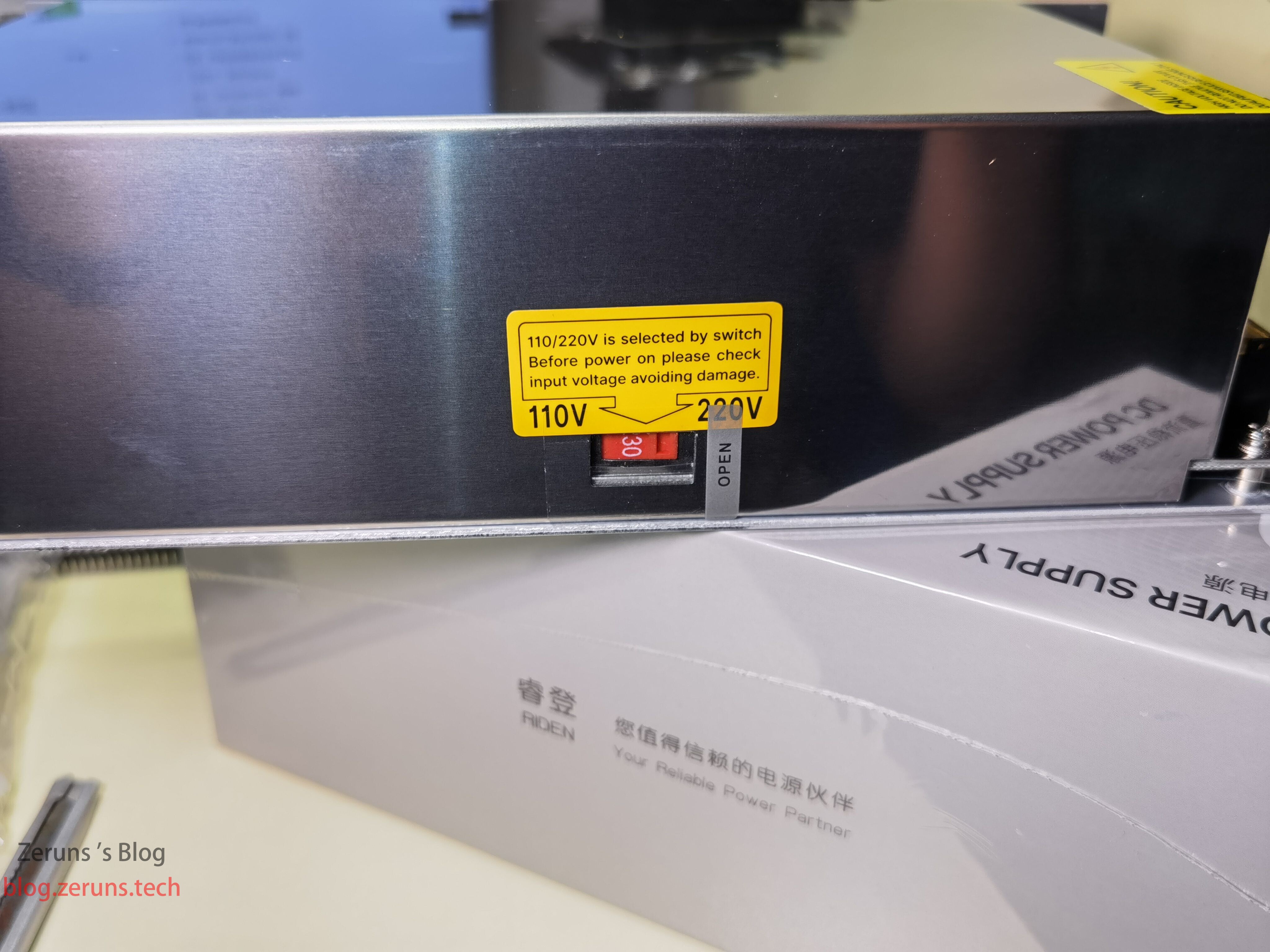
Other side of the pre-stage power supply has a switch to select between 110V and 220V input.
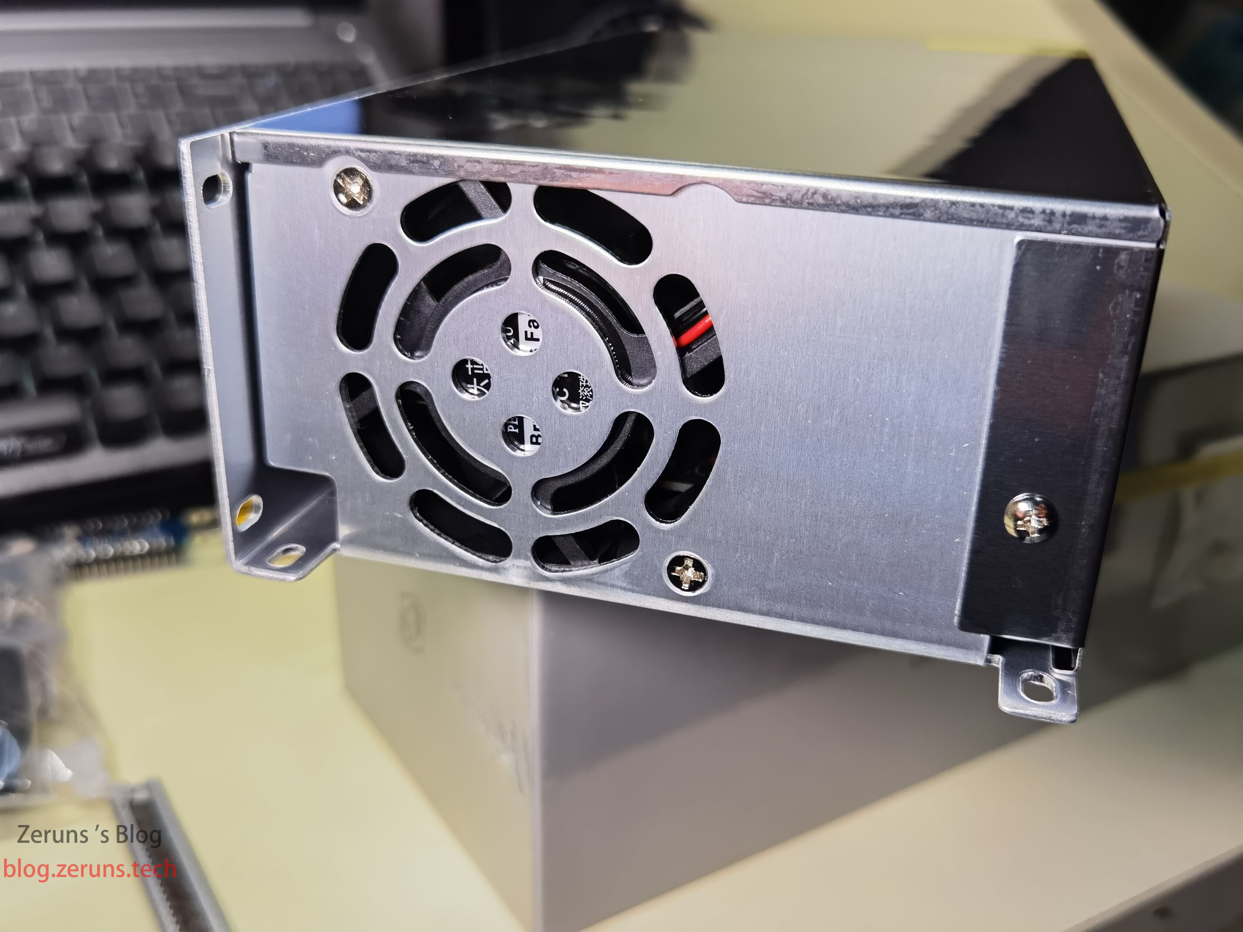
Back of the pre-stage power supply, featuring a cooling fan.
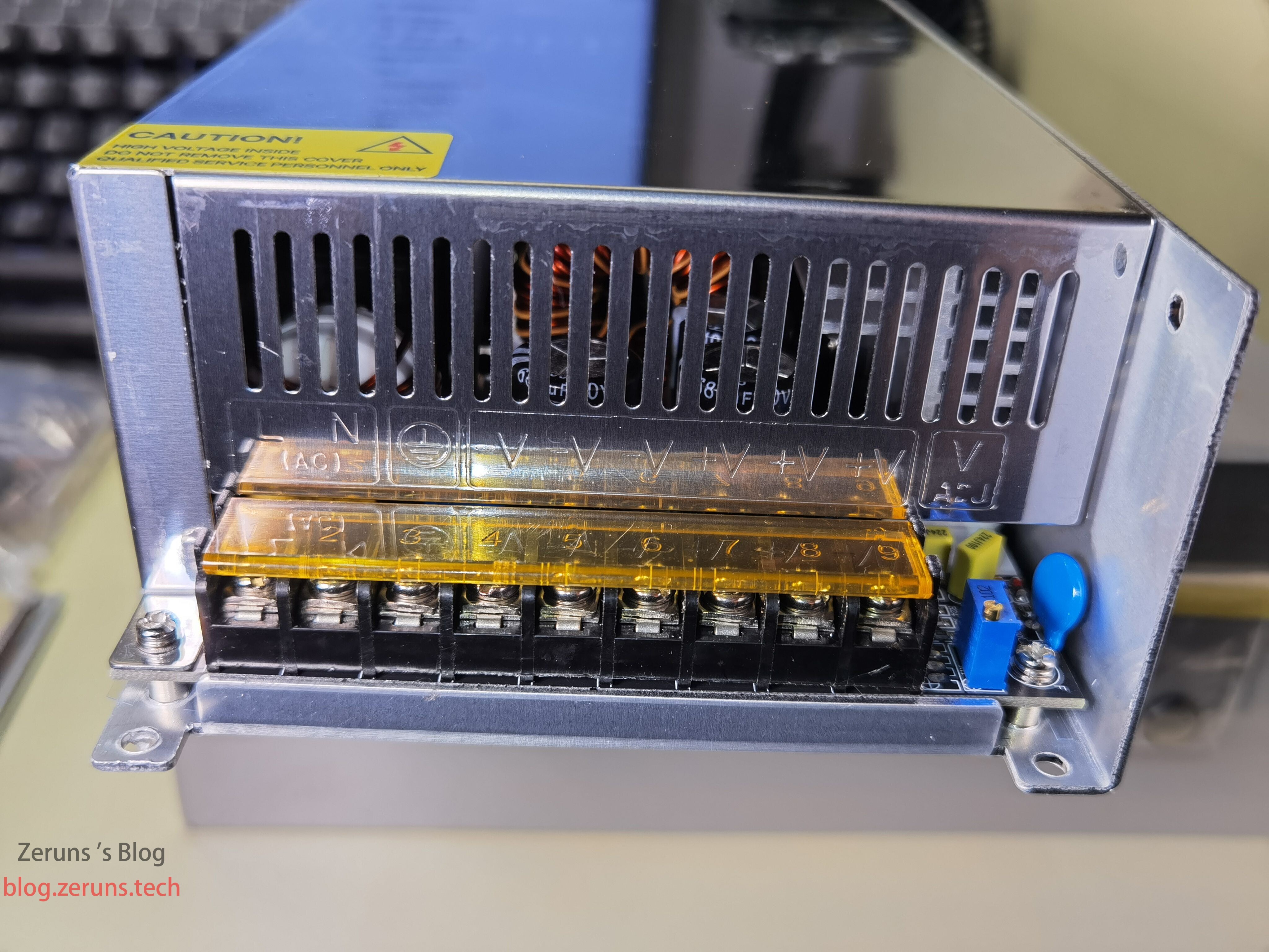
Terminal block on the pre-stage power supply: from left to right—Live, Neutral, Ground, Negative, Positive. There’s also a voltage fine-tuning potentiometer on the right.
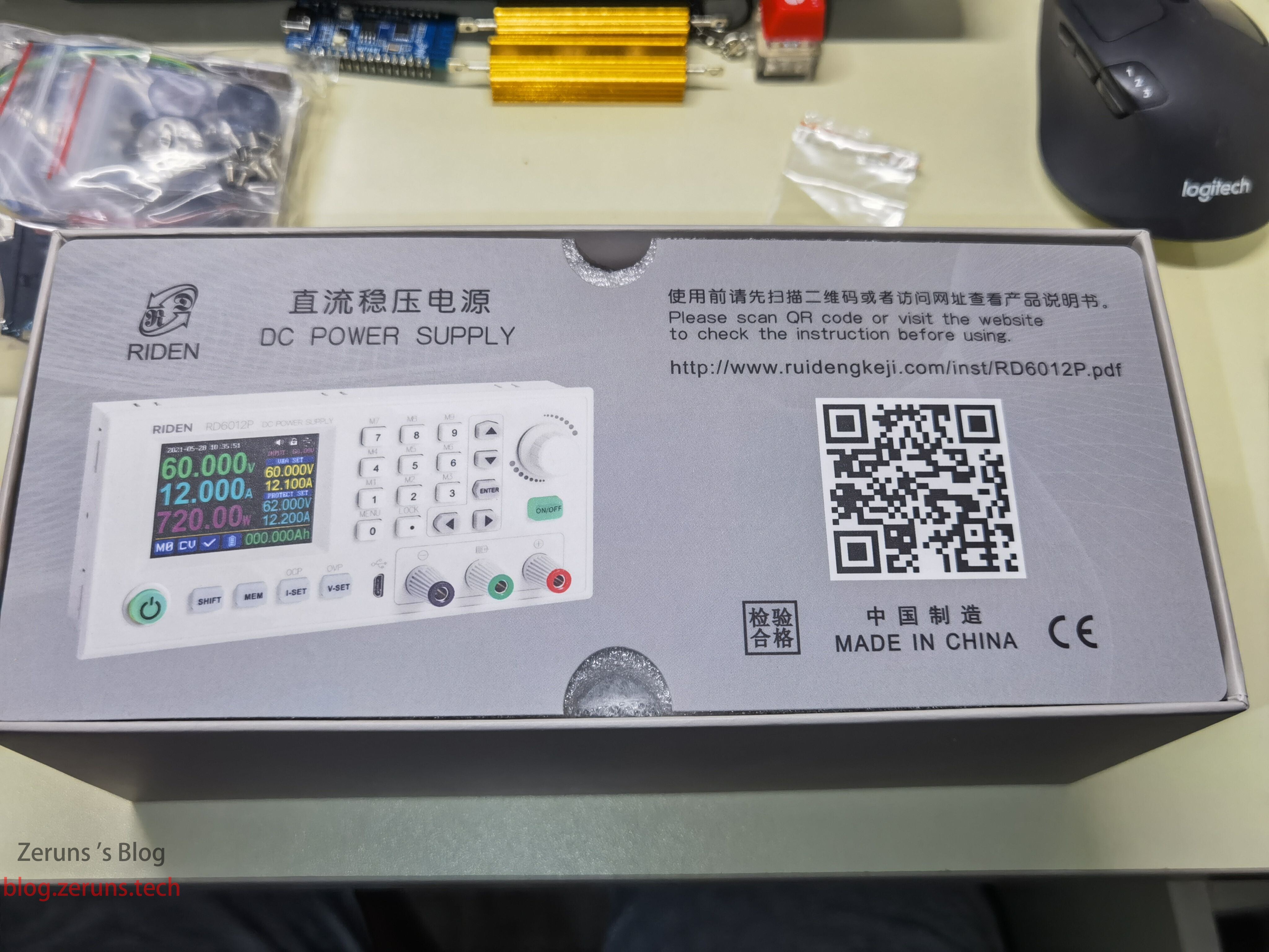
Front of the RD6012P-W box, with a button battery attached (for RTC—real-time clock), as this power supply has time display functionality.
Bottom of the RD6012P-W box.
Unboxing the RD6012P-W: first item is a QR code card for the user manual.
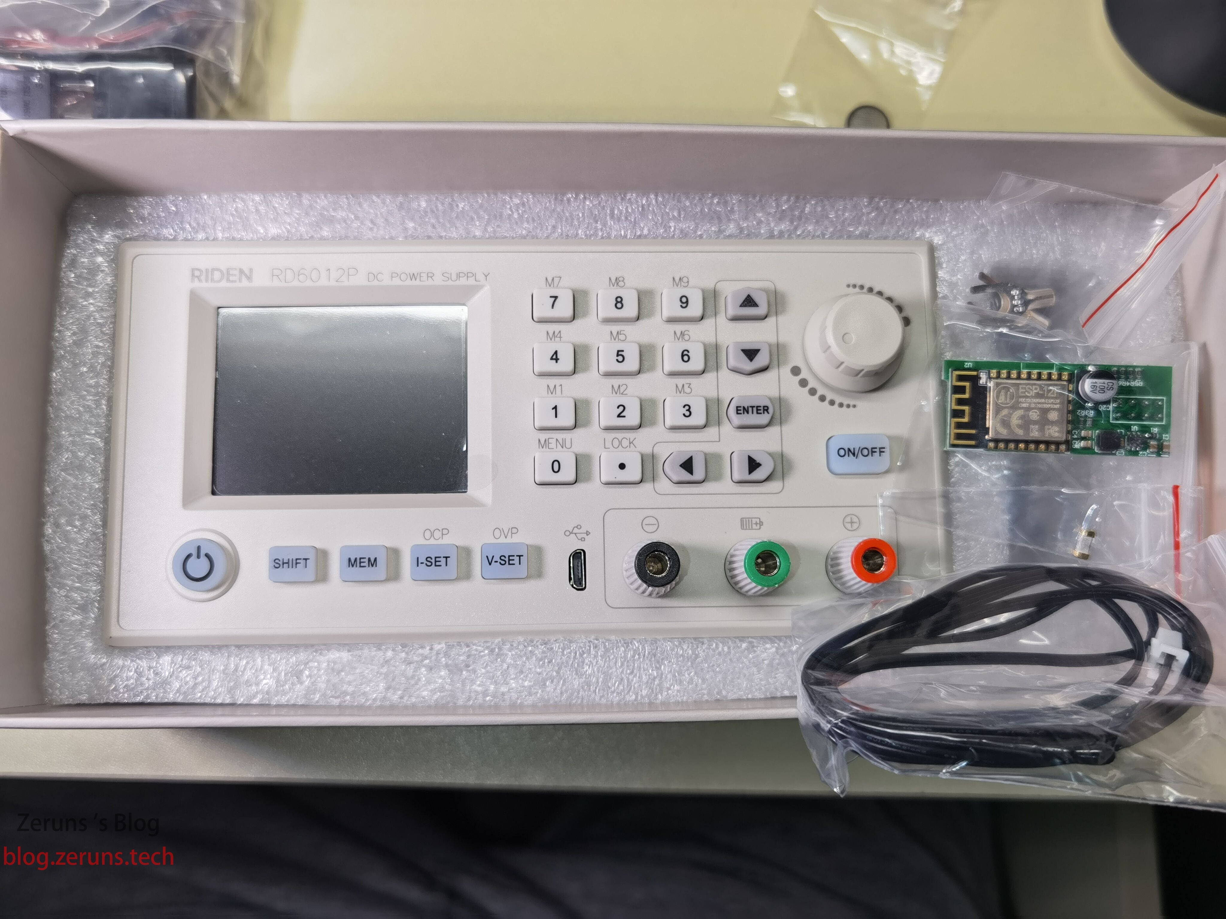
Left: RD6012P-W unit; Right: accessories including WiFi module, temperature probe, and 20A fuse.
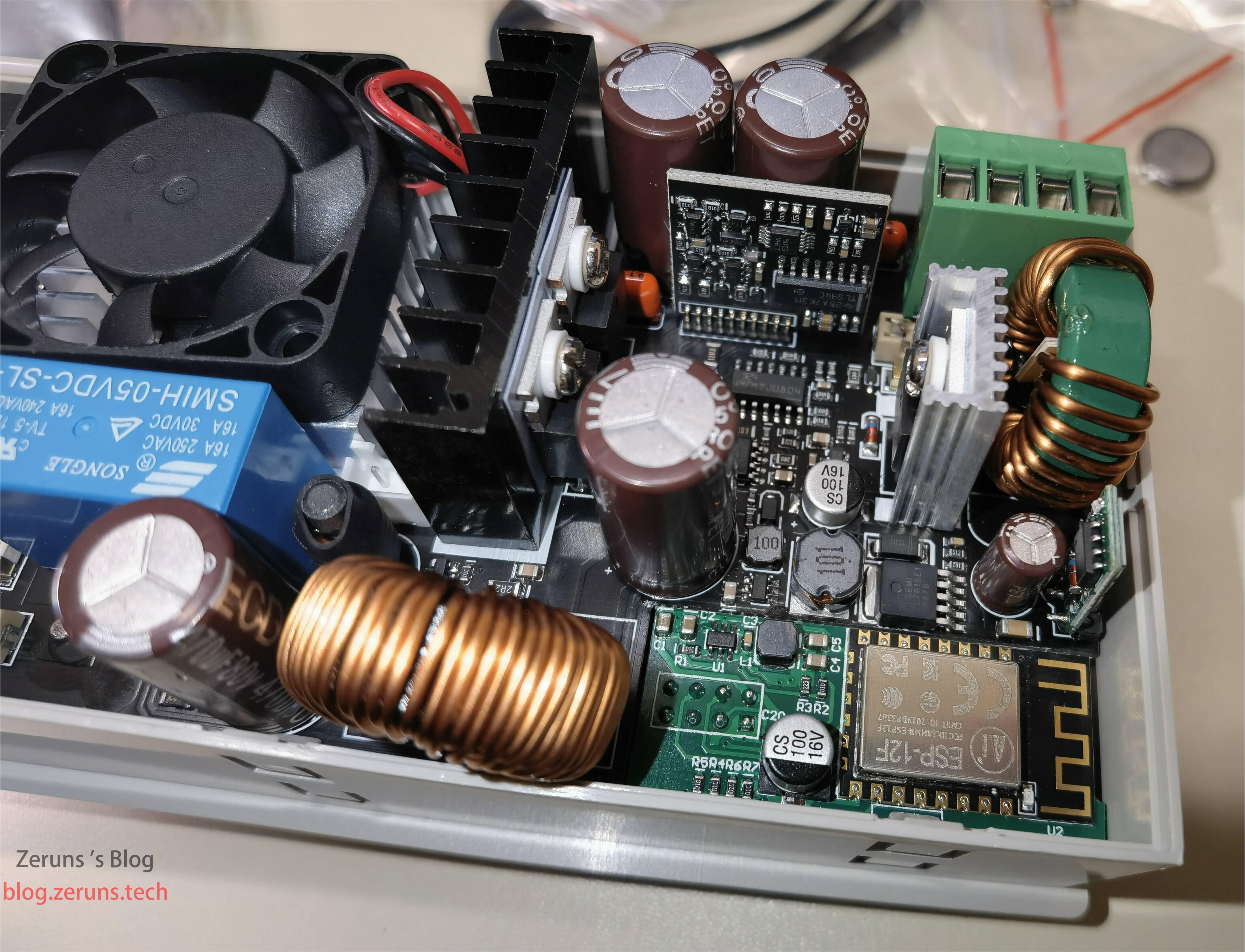
Back of the RD6012P-W.
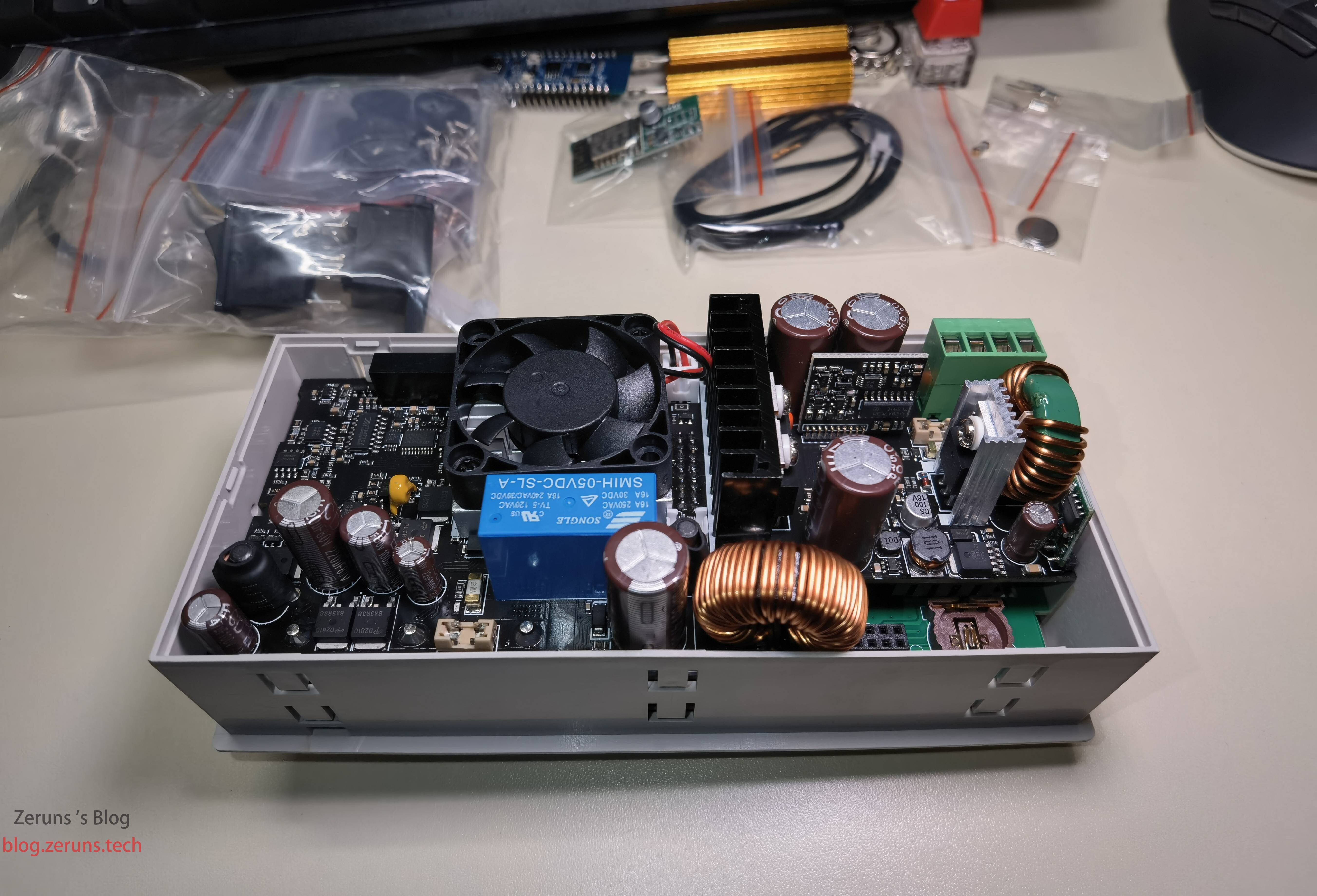
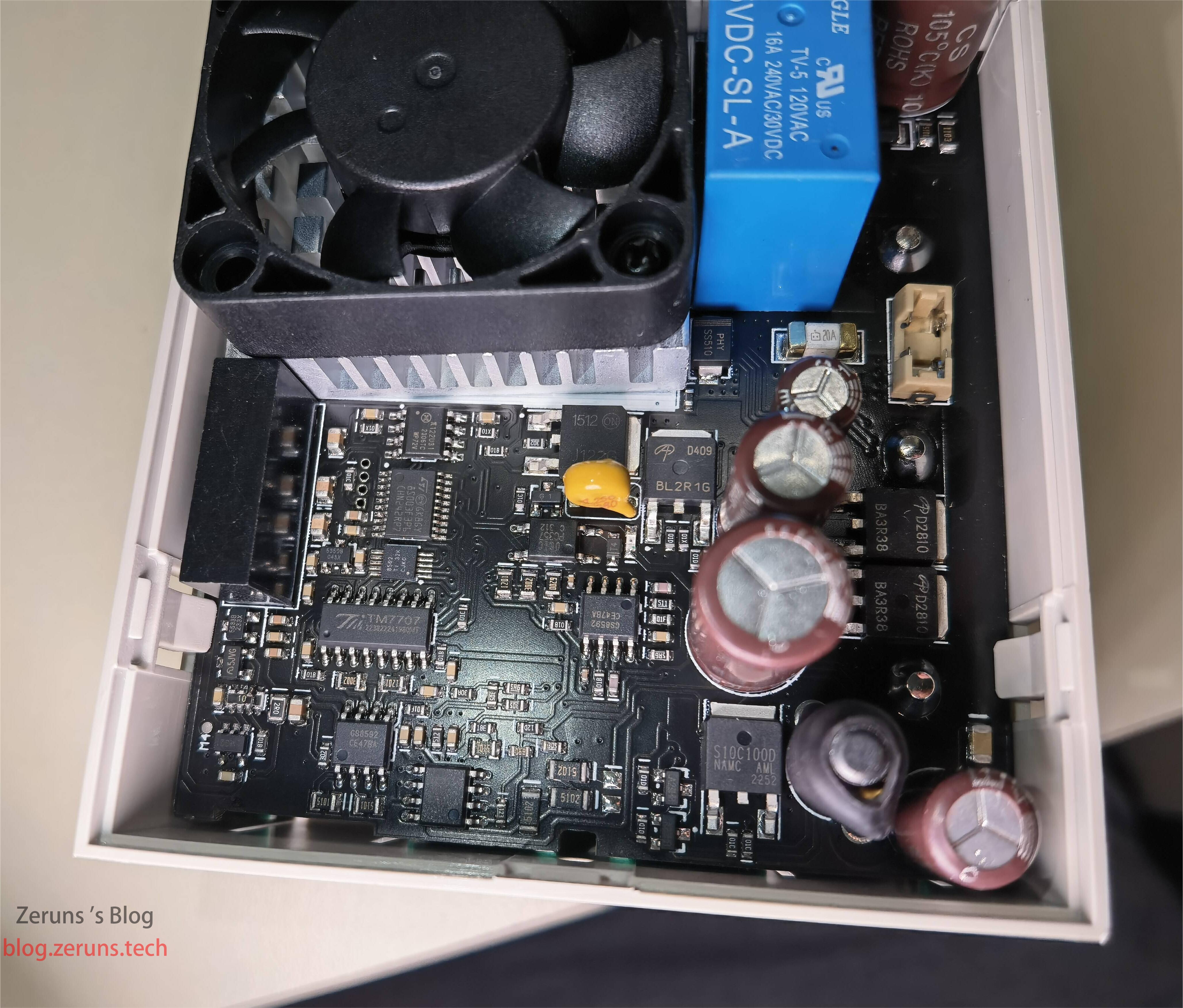
Linear regulator section: center is an 8-bit MCU STM8S003F3P6, below it a TI DAC8562 (dual-channel 16-bit DAC), then TM7707 (dual differential 24-bit ADC), followed by GS8592 (dual op-amp). Above the MCU is π122U31 (dual-channel digital isolator), to its right MJD122G (Darlington transistor), then AOD409 (P-channel MOSFET), followed by two AOD2810 (N-channel MOSFETs), and below them S10C100D (Schottky diode).
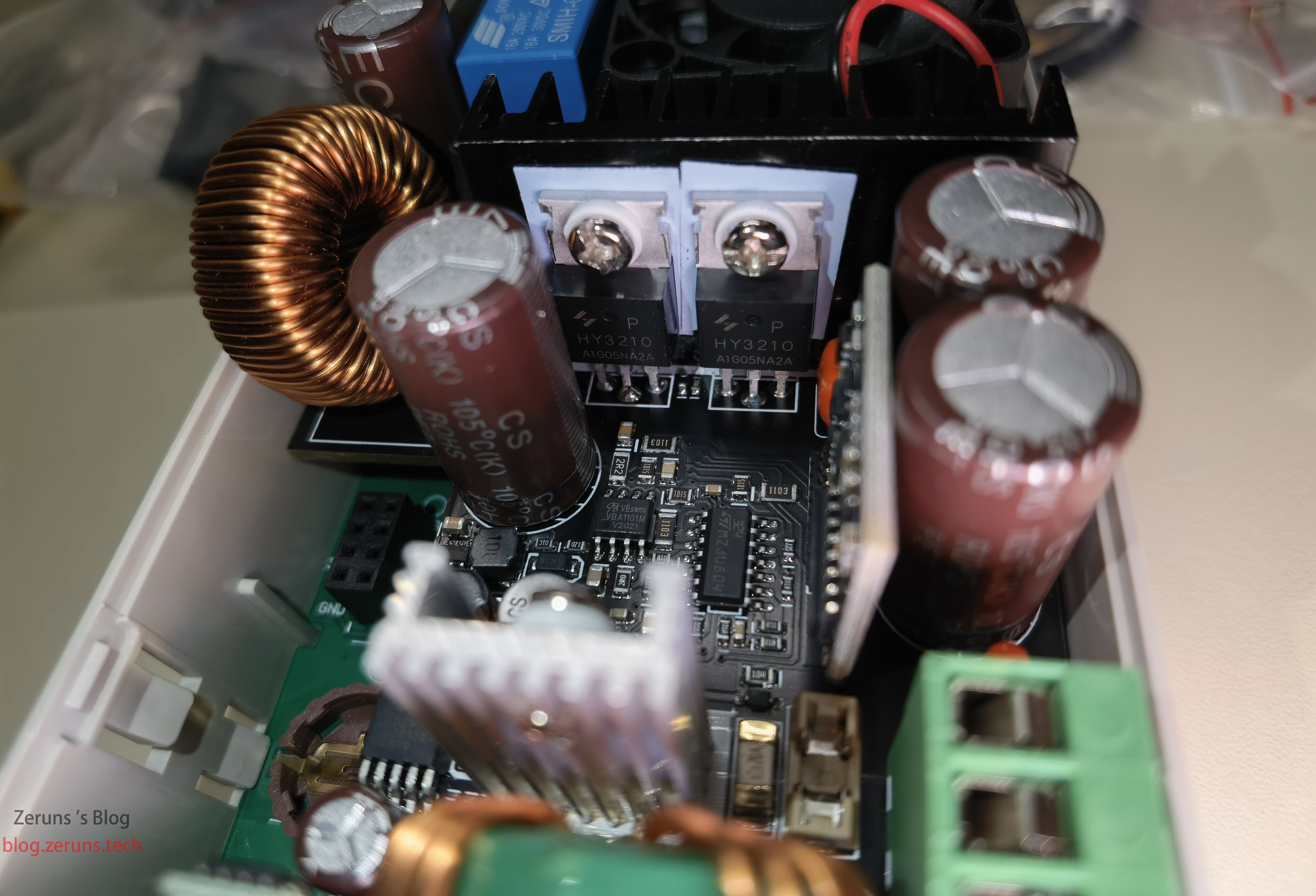
Switching power supply section: two MOSFETs under the black heatsink, model HY3210, likely used in synchronous rectified buck configuration. Capacitor brand appears to be “CS” (not sure if this is a brand or series—anyone know?).
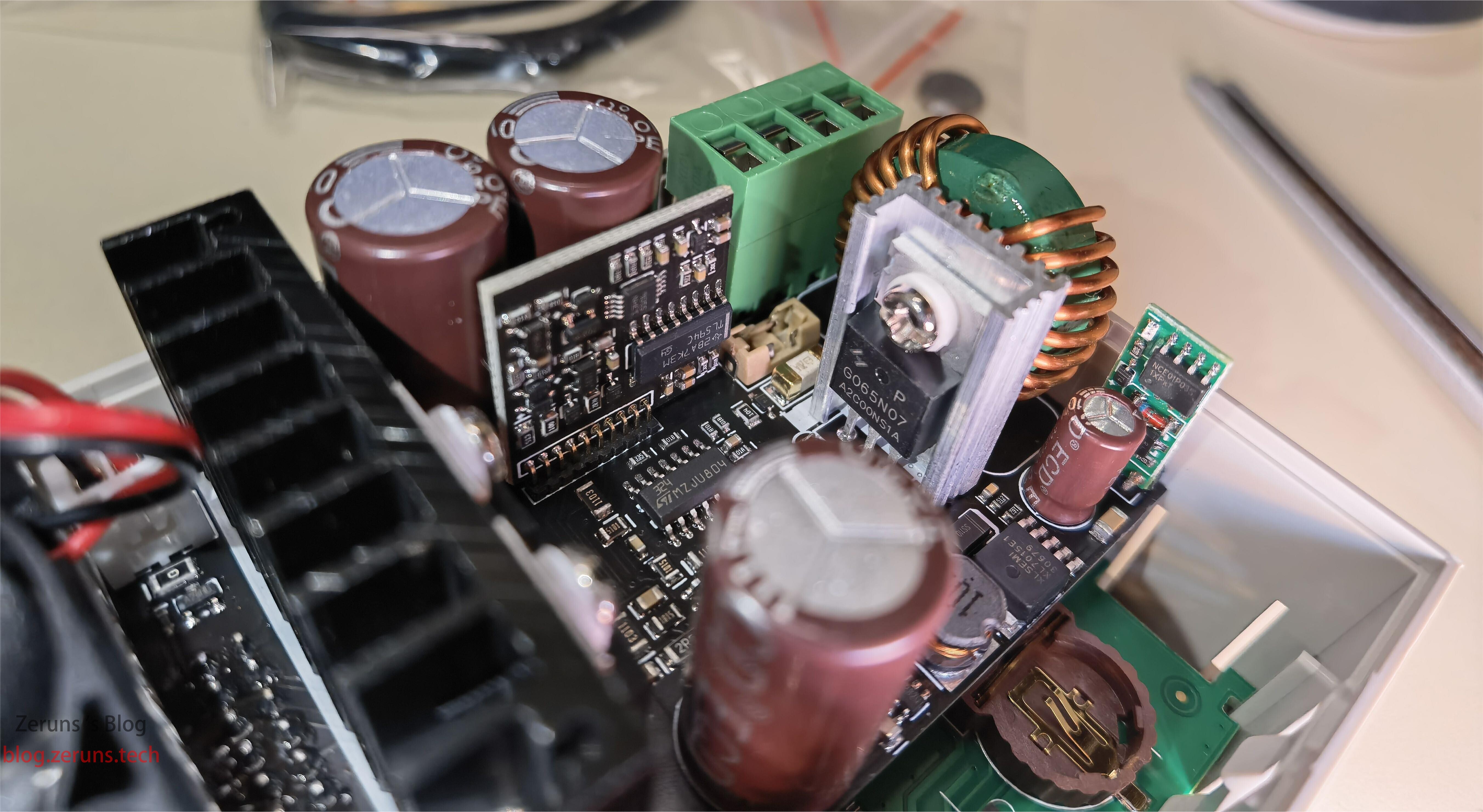
16-pin chip on the small black PCB is TL594, likely the PWM controller for the switching section. MOSFET to the right is GO65N07. To the right of the MOSFET is XL7015E1 (buck converter IC), likely used for auxiliary power.
After installing the WiFi module: the module is ESP-12F.
Wiring diagram.
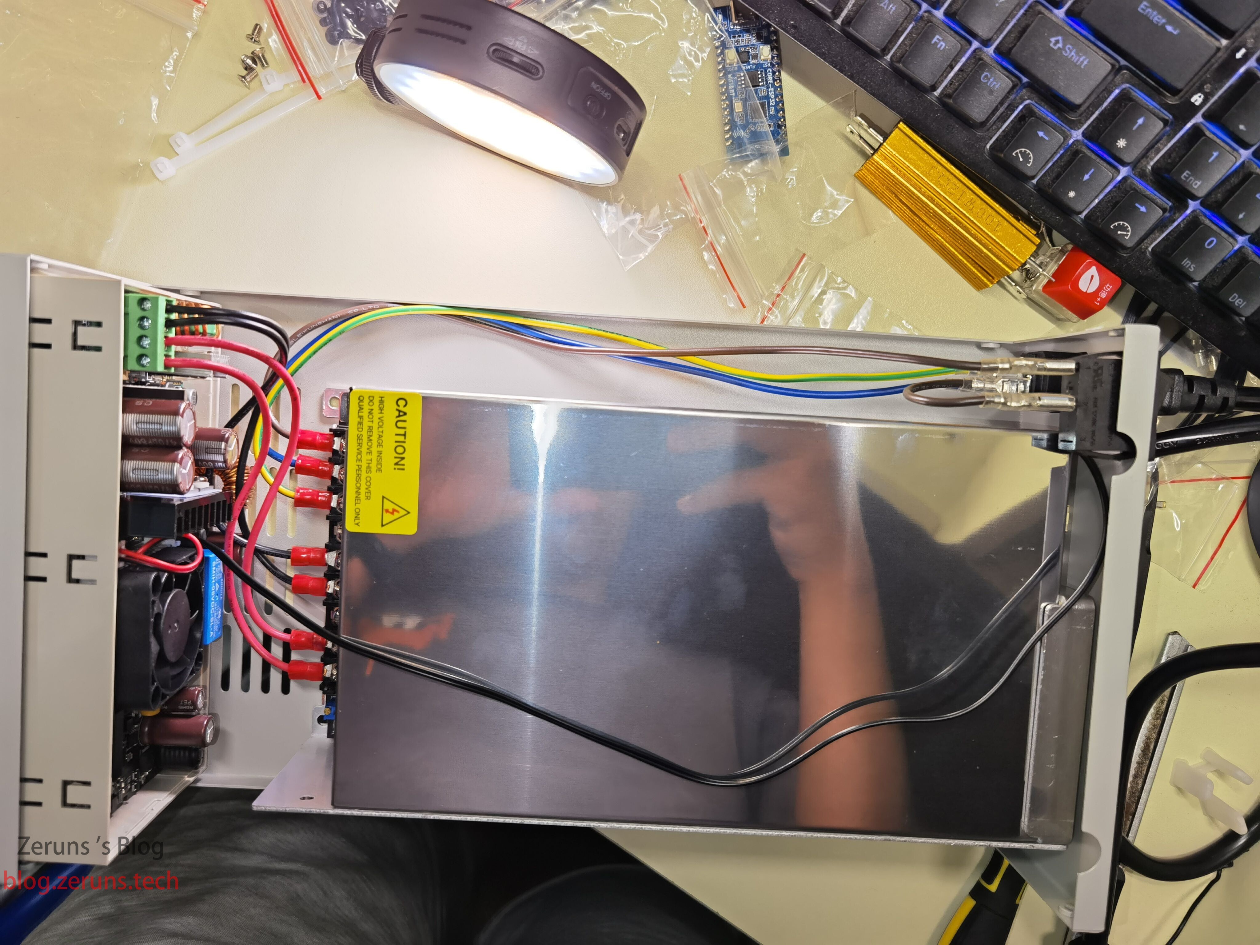
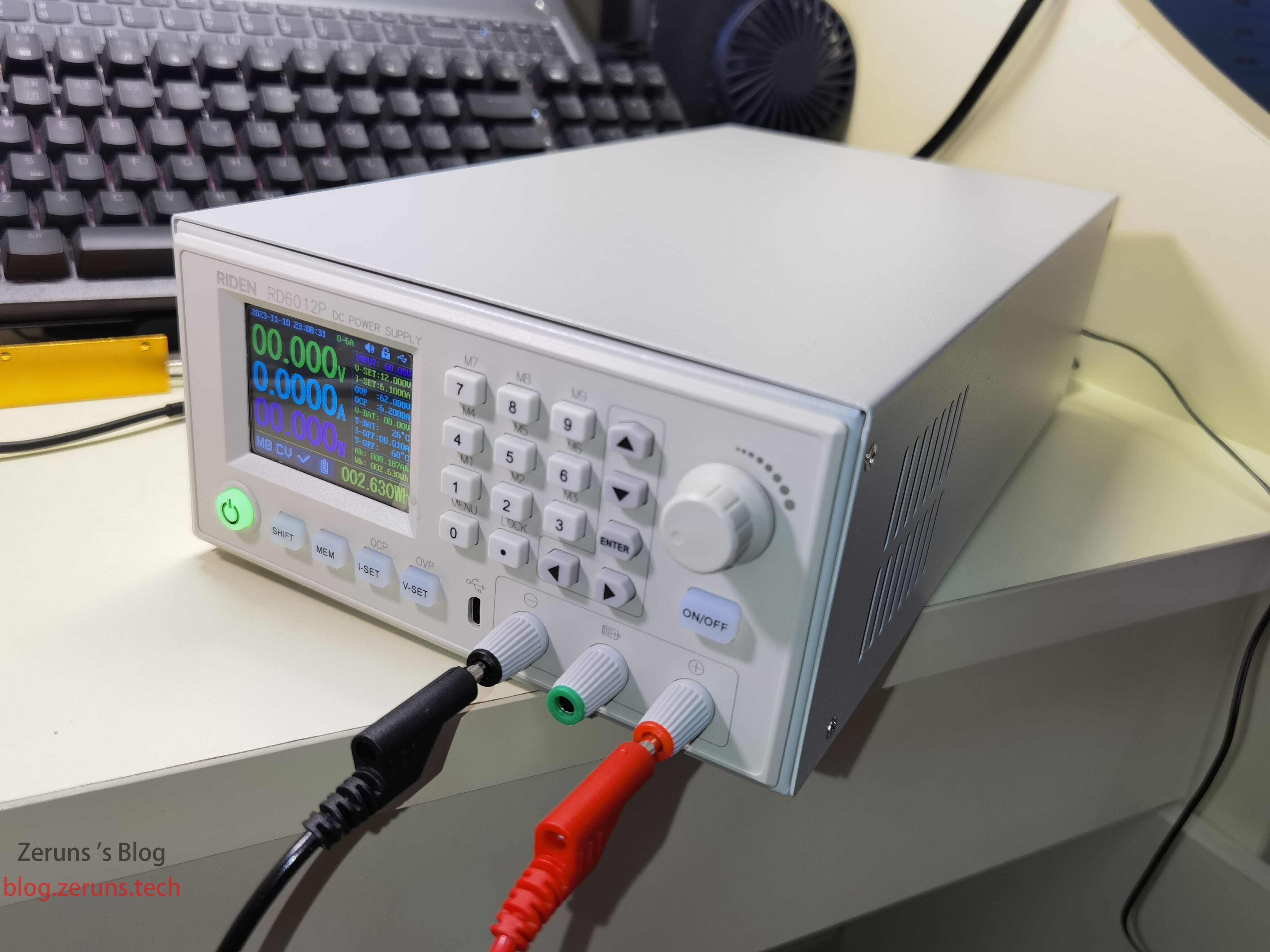
Fully assembled unit.
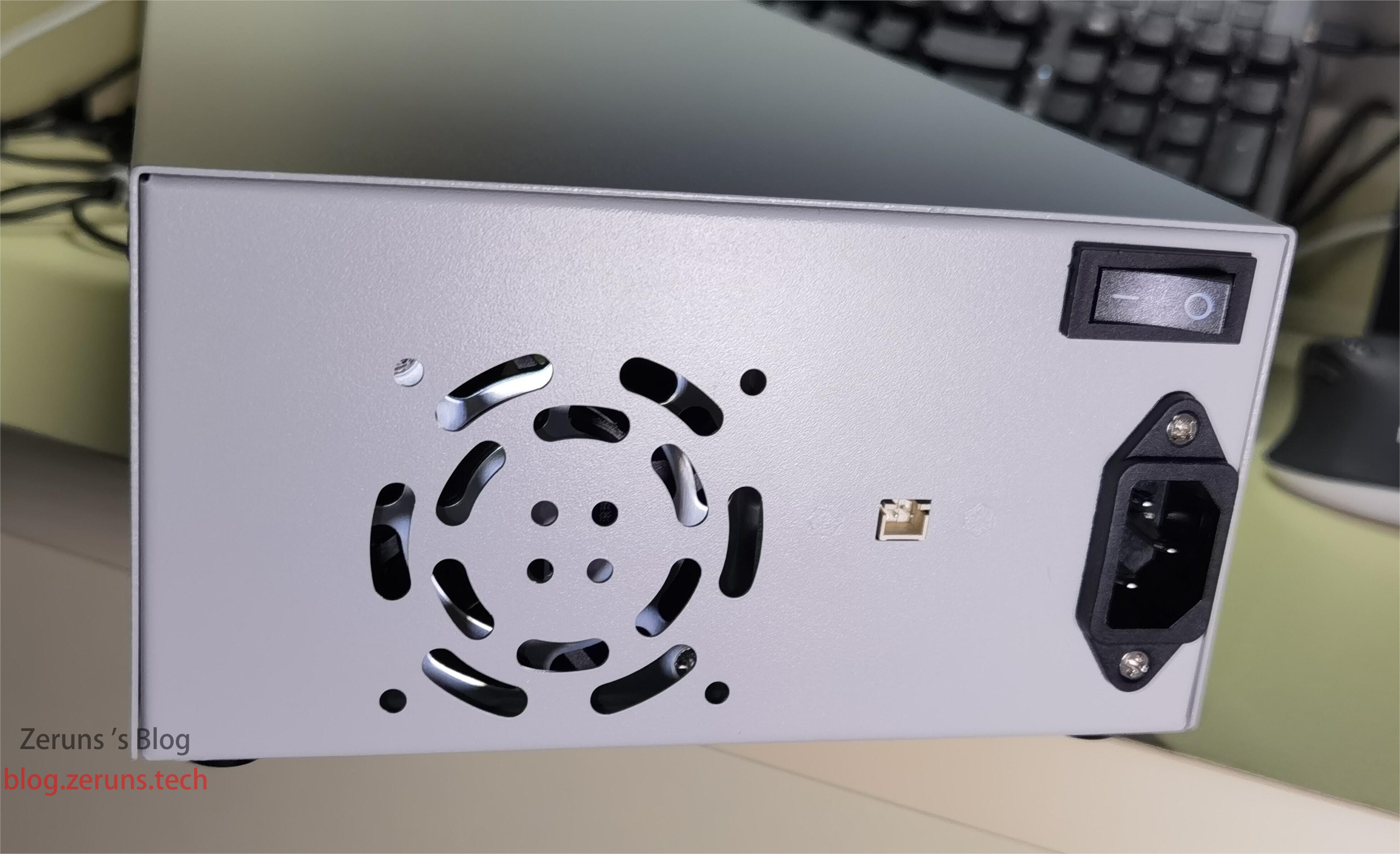
Back of the power supply.
Review
The multimeter used in testing is a Victo VC86E, a 4.5-digit model. Test results are for reference only—equipment is limited, no higher-precision instruments available.
No-Load Power Consumption and Efficiency Test
No-load power consumption is slightly over 1W.
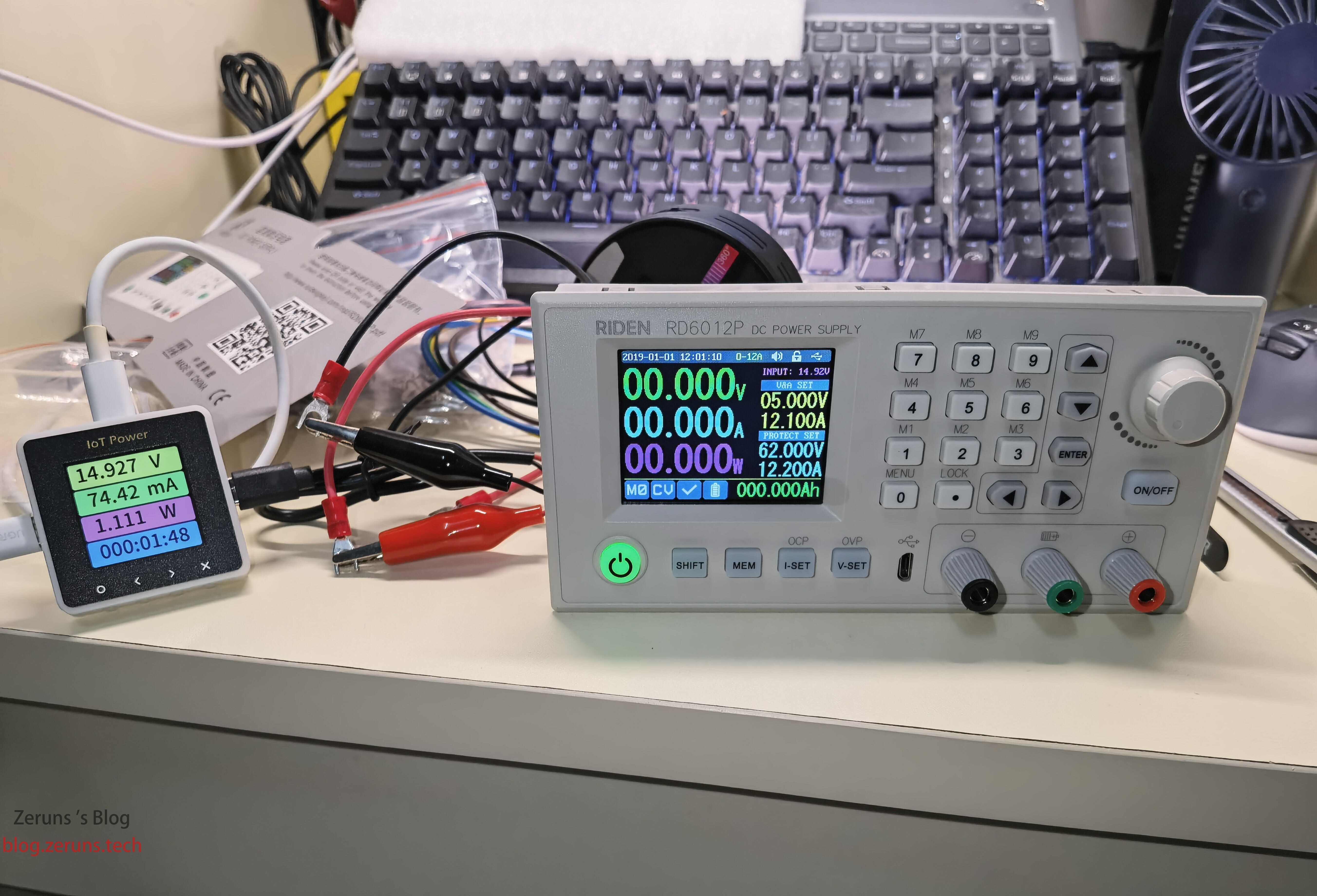
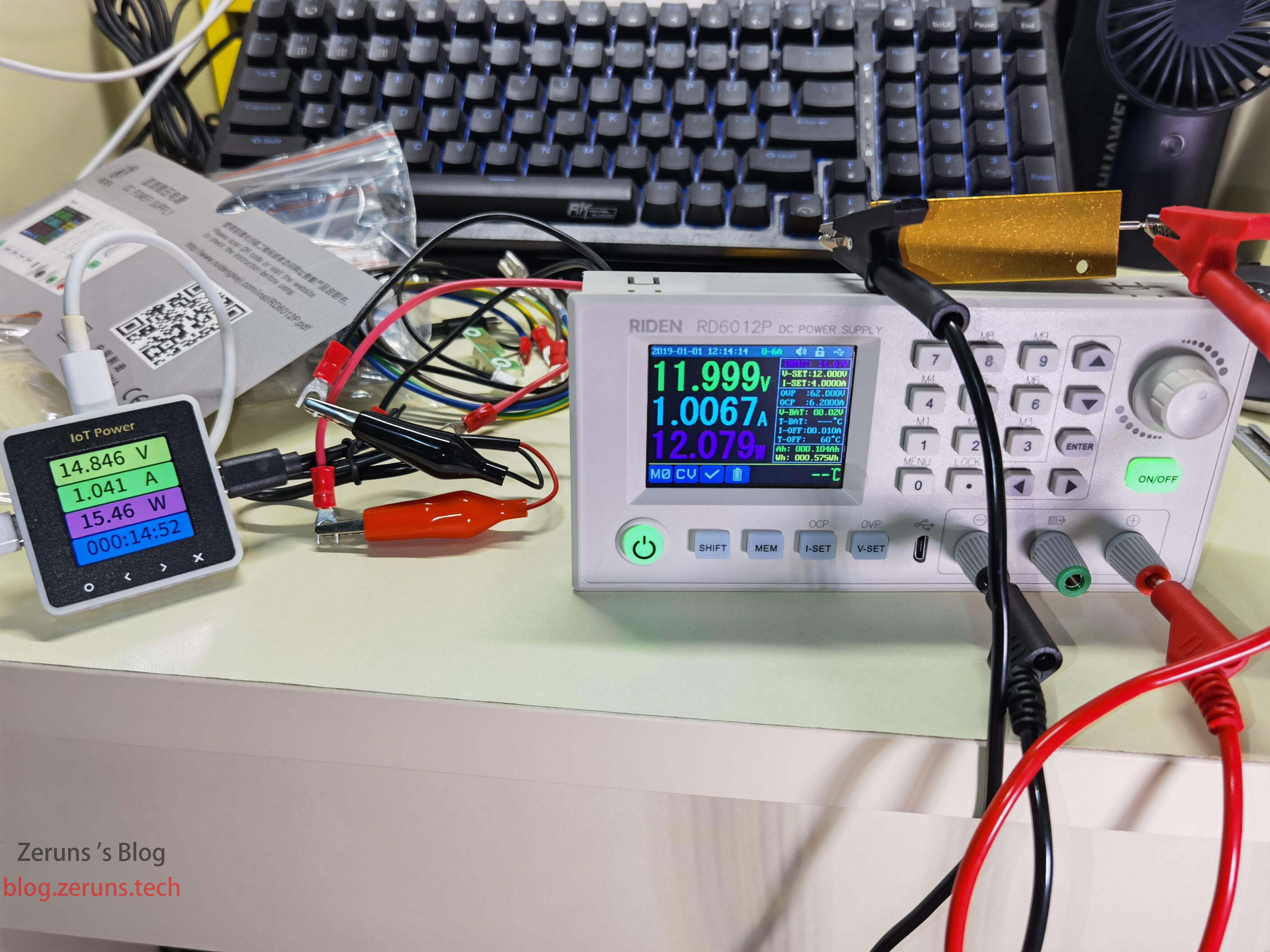
Efficiency test: at 15V input, 12V/1A output, efficiency is approximately 78%. Efficiency may improve with higher input voltage.
Constant Current Output Accuracy and Current Readback Test
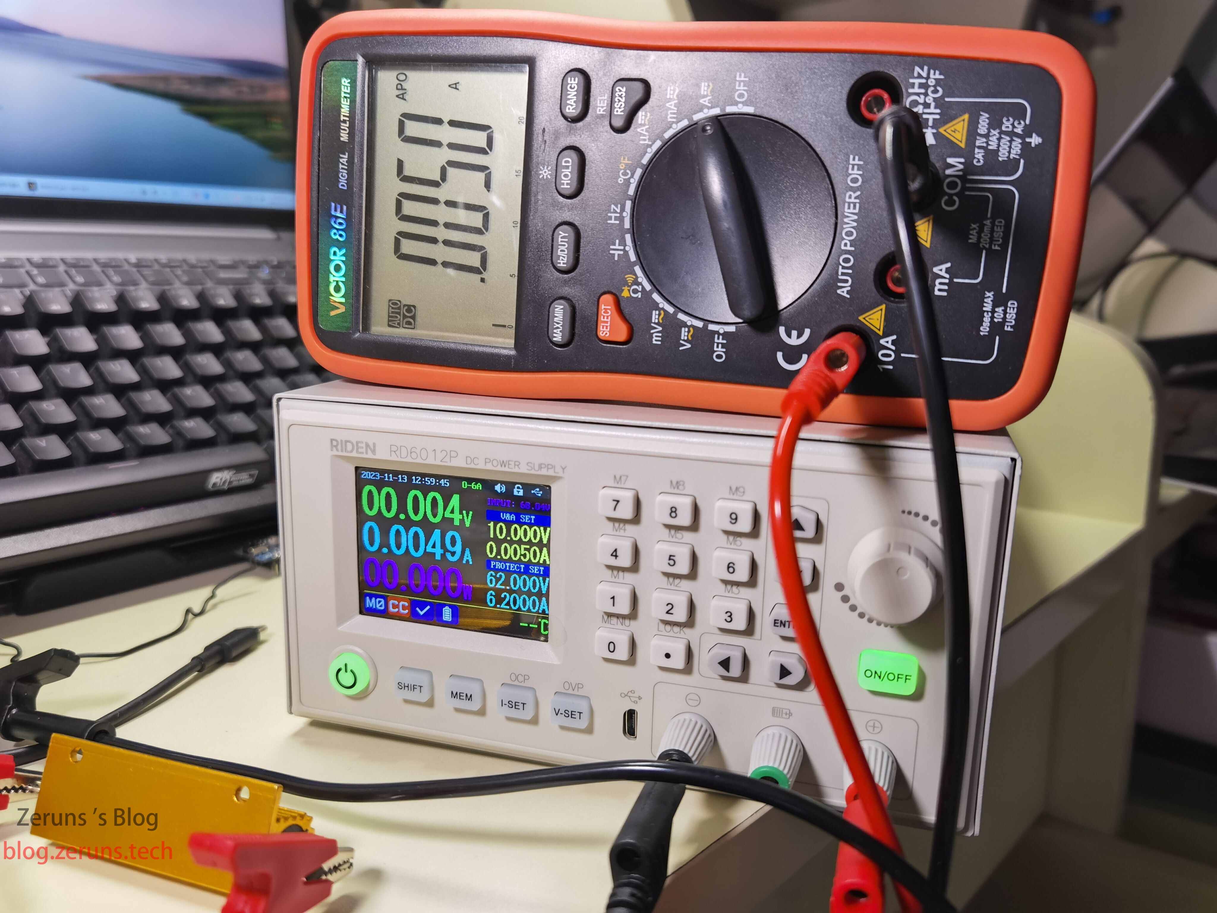
Load: 1Ω resistor. Set output voltage to 10V, output current to 0.005A. Power supply displays 0.0049A, multimeter reads 0.005A.
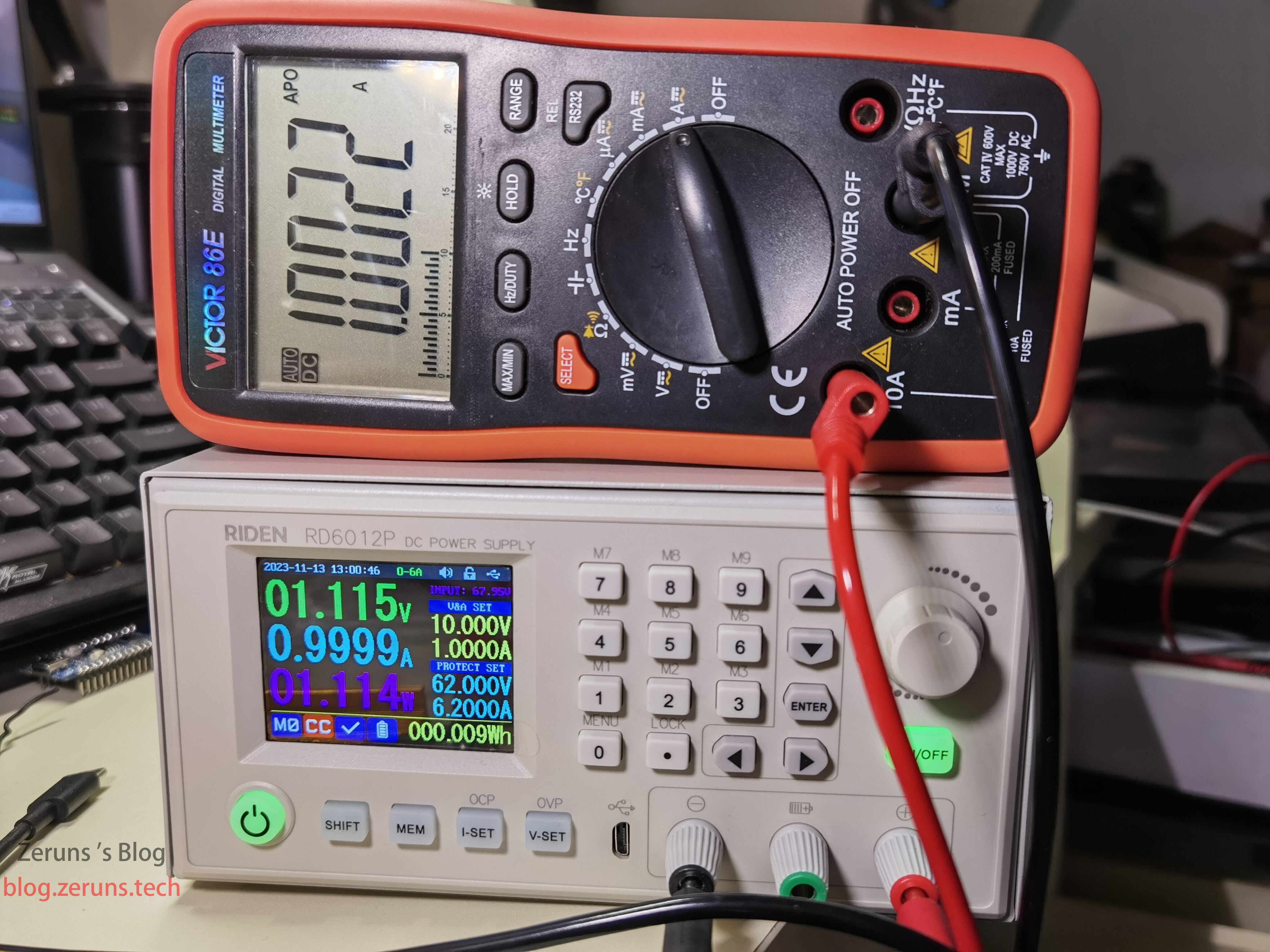
Set output current to 1A: supply shows 0.9999A, multimeter reads 1.0022A.
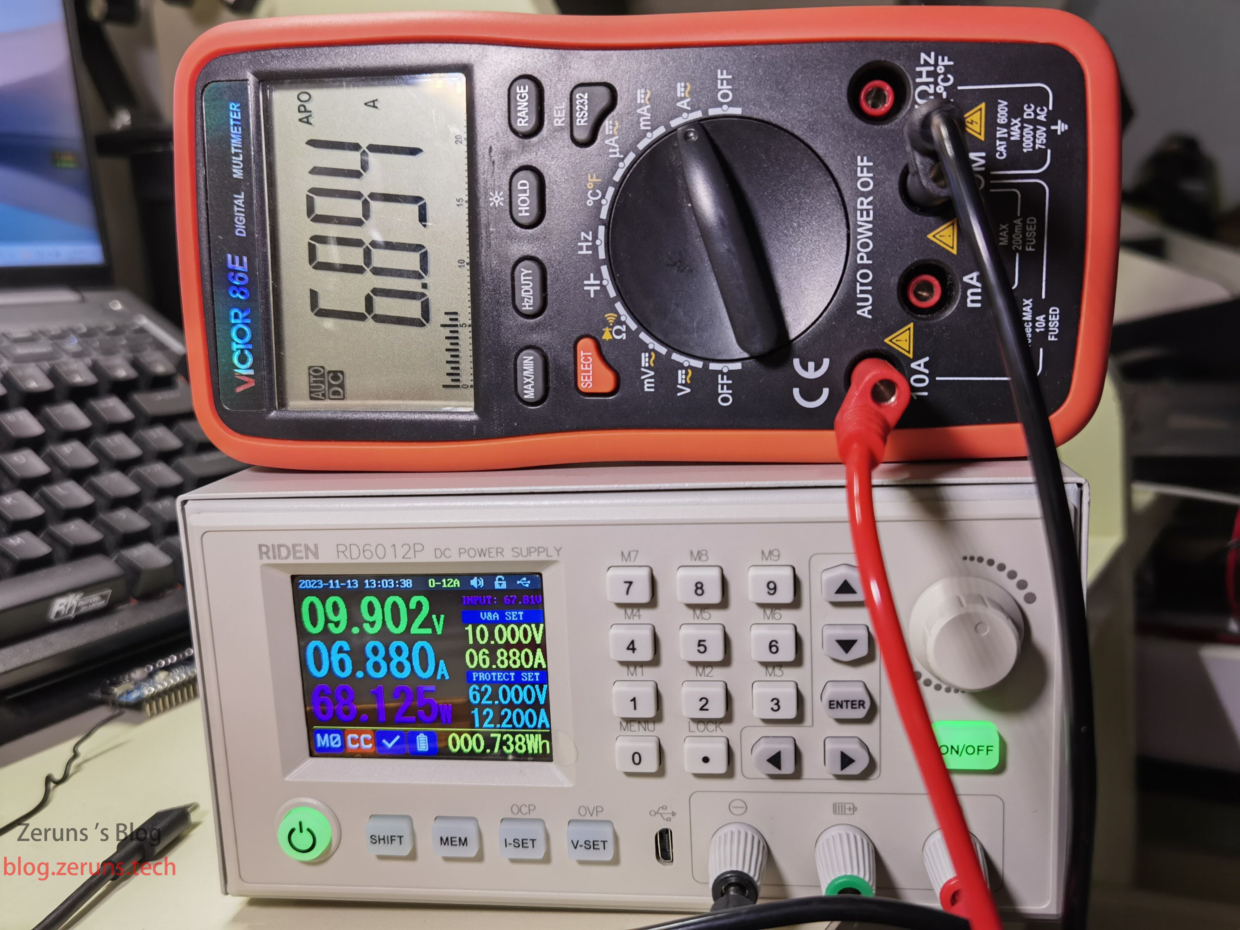
Switched to 12A range, set output current to 6.88A: supply shows 6.88A, multimeter reads 6.894A.
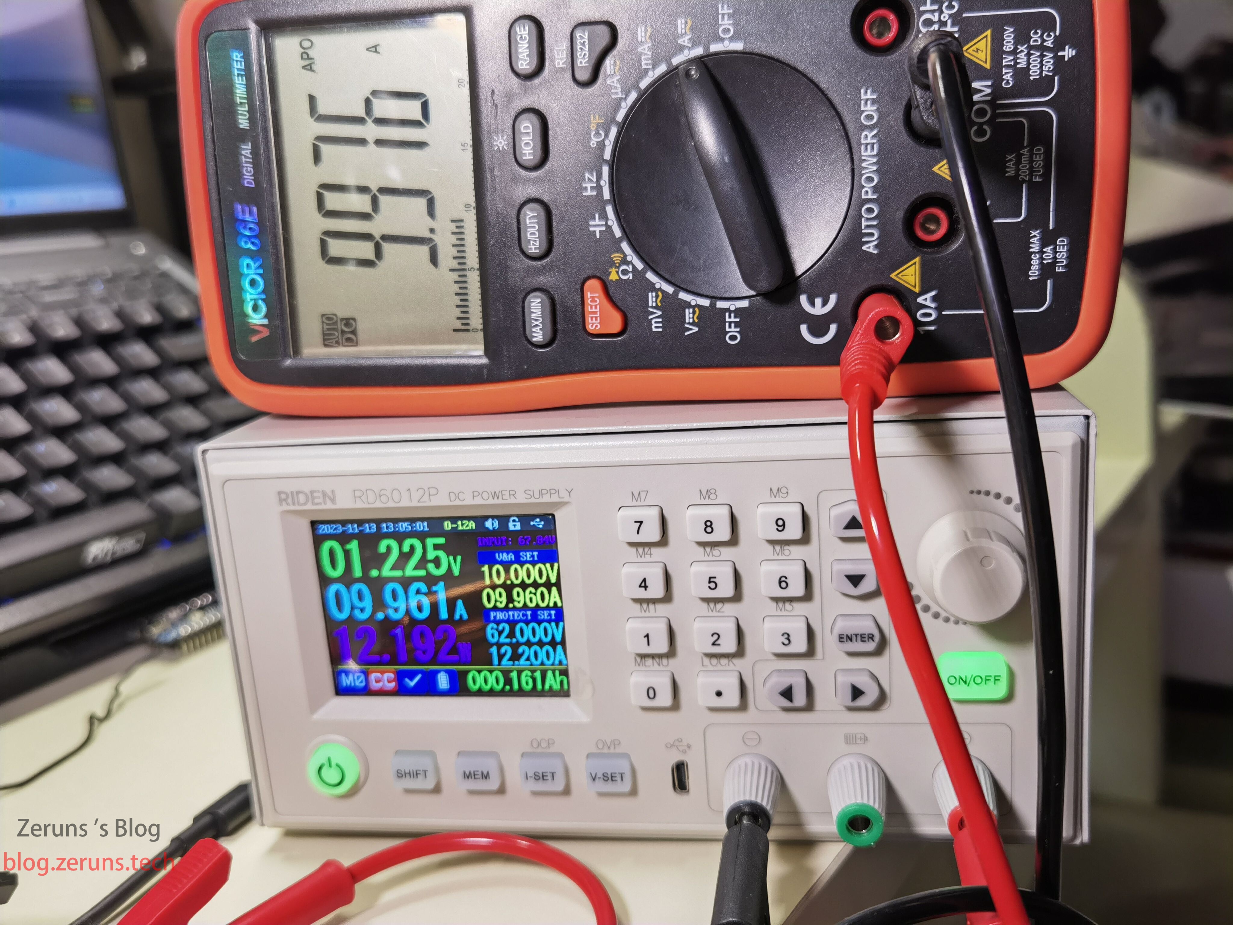
Shorted output directly to multimeter, set output current to 9.96A: supply reads 9.961A, multimeter reads 9.976A.
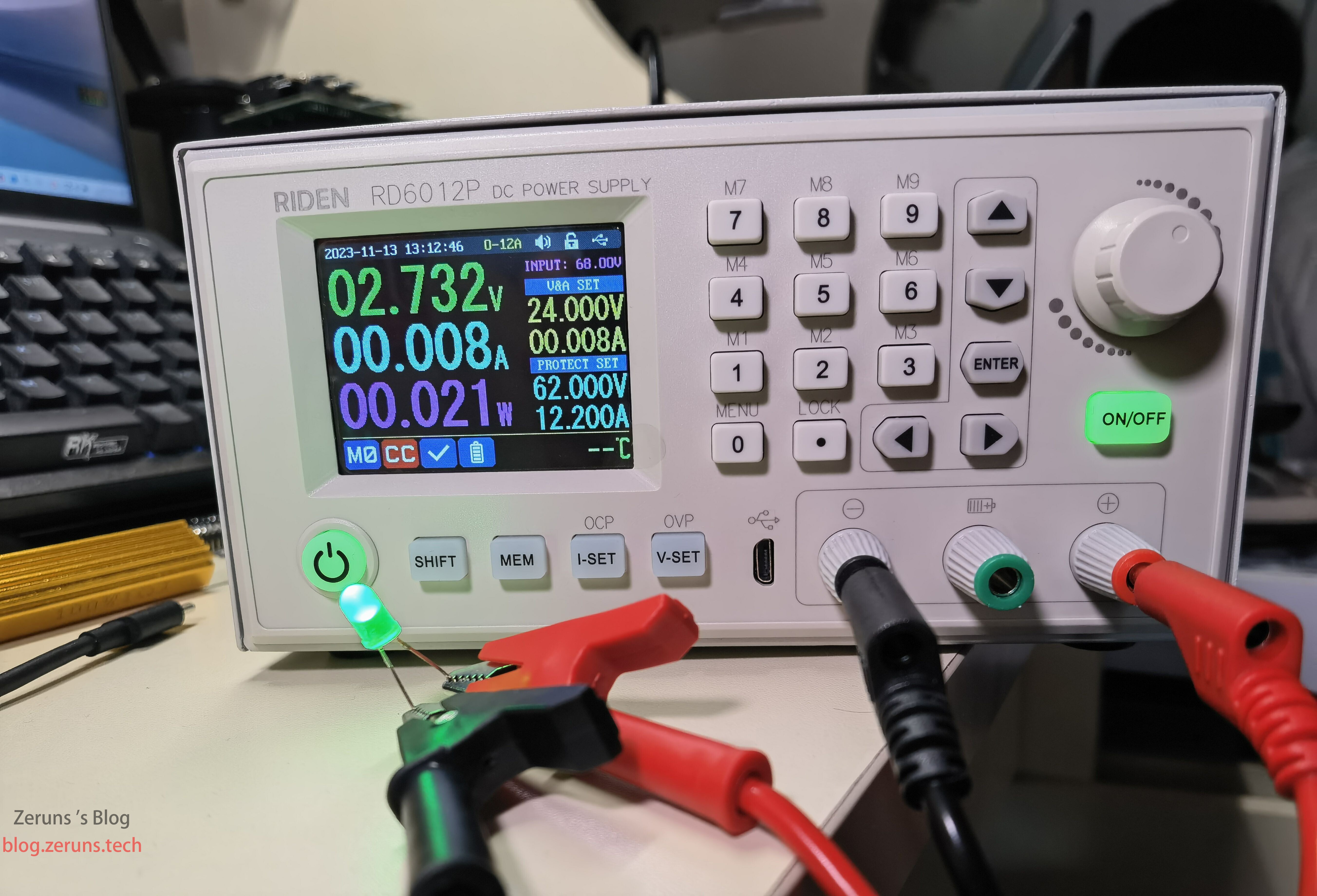
Constant current stability test: set 24V/0.008A output, connected to an LED. Upon enabling output, current stabilizes at 0.008A with no LED flickering—excellent stability. Previously used a lower-quality adjustable supply; same test caused noticeable LED flickering due to unstable constant current output.
Voltage Output Accuracy and Voltage Readback Test
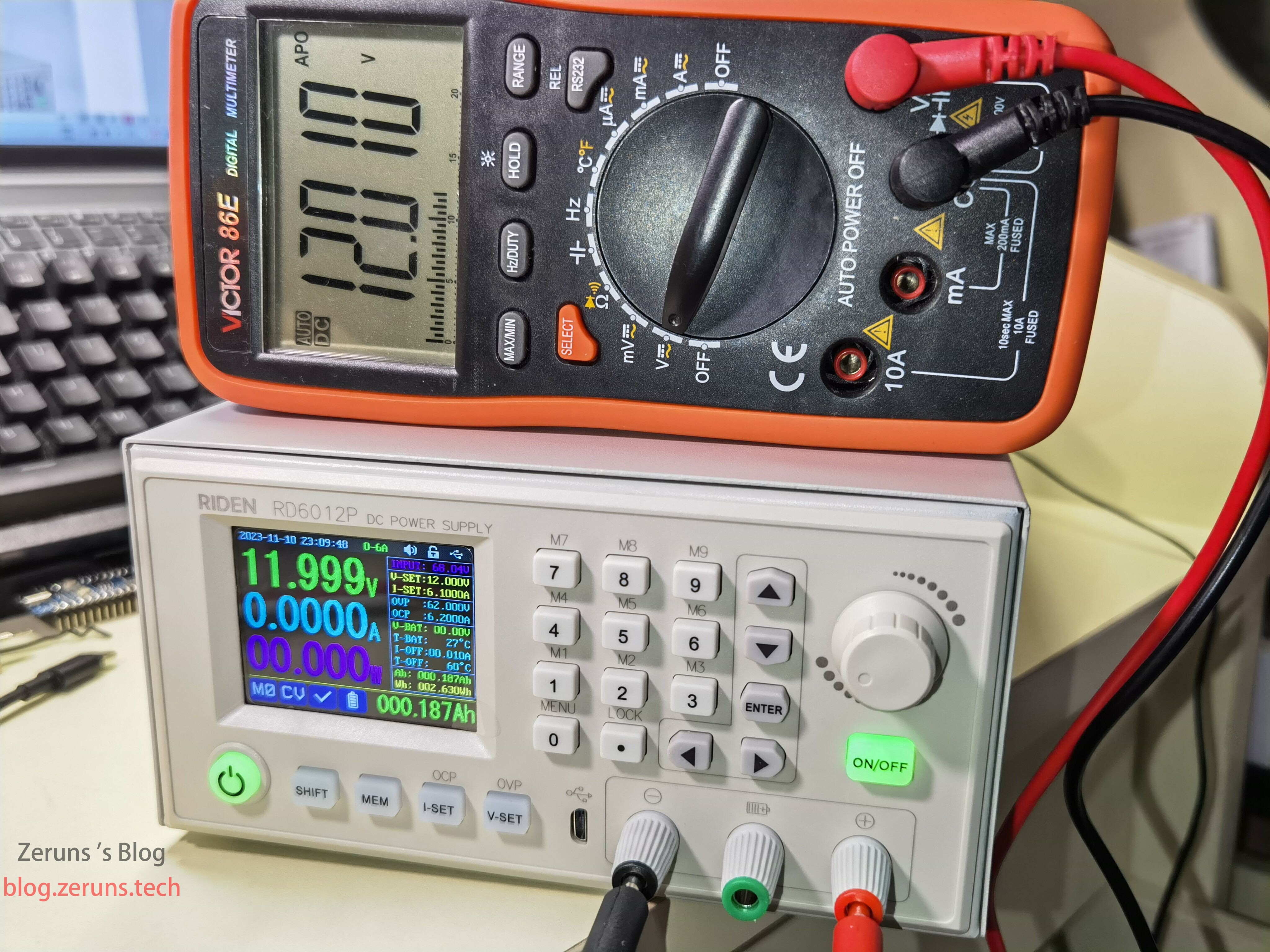
Set output voltage to 12V: supply displays 11.999V, multimeter reads 12.01V.
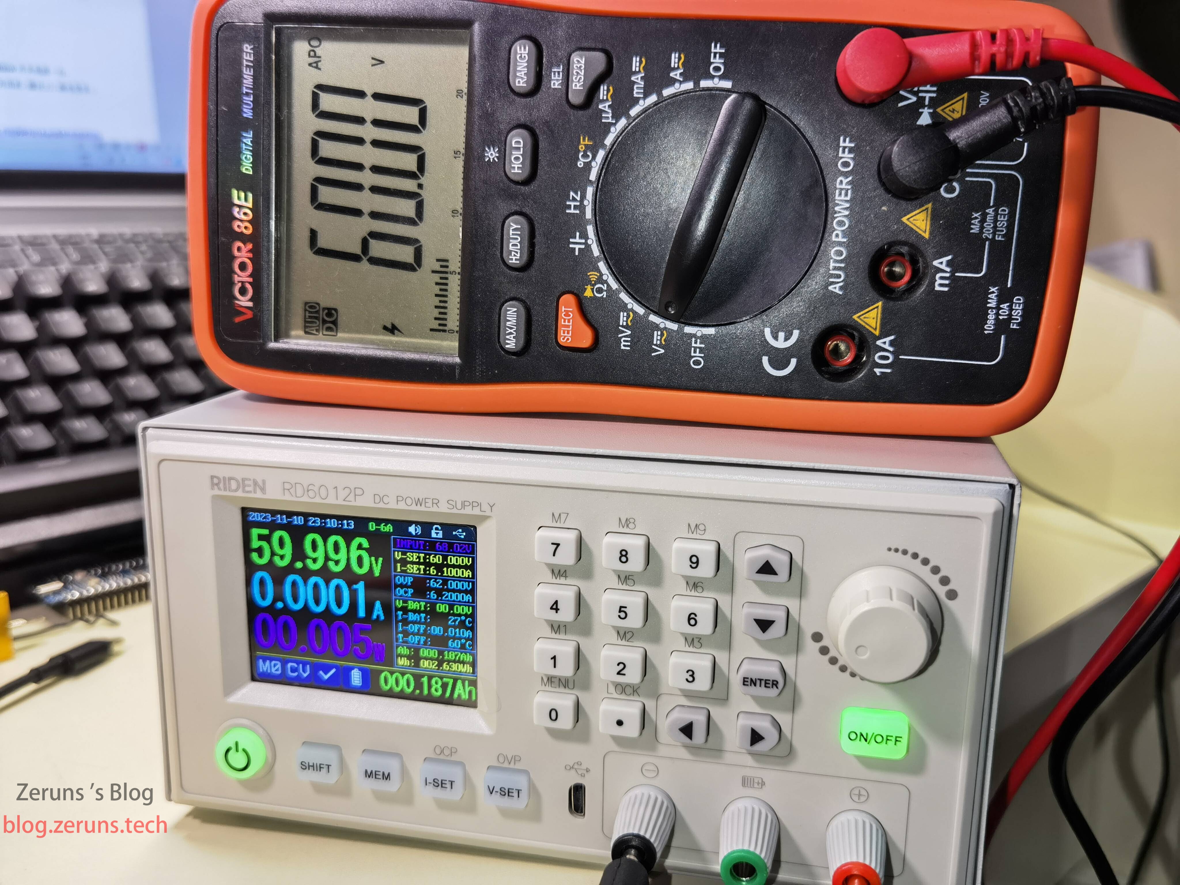
Set output voltage to 60V: supply shows 59.996V, multimeter reads 60.00V.
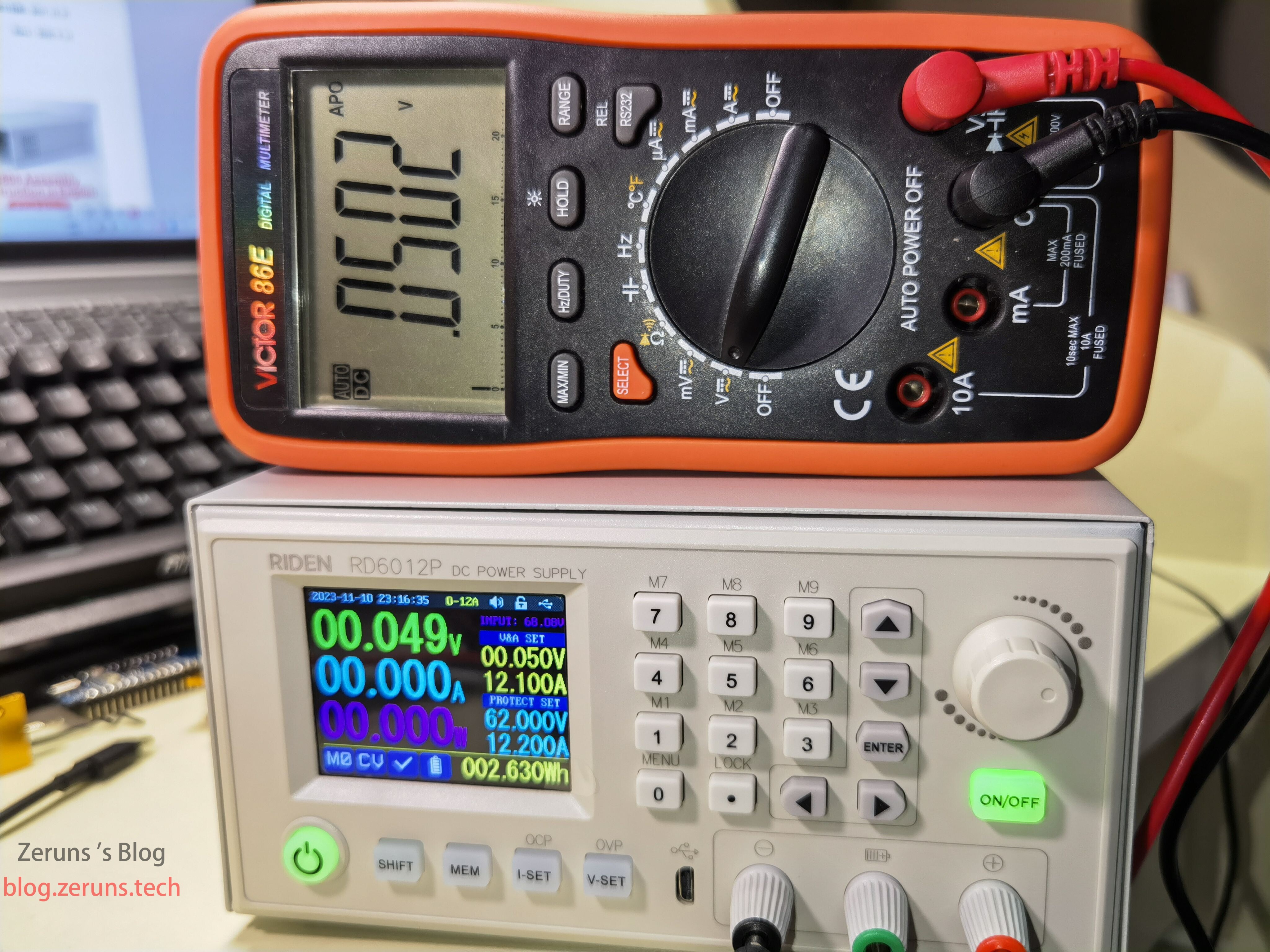
Set output voltage to 0.05V: supply shows 0.049V, multimeter reads 0.0502V.
Ripple Test
The following ripple measurements were taken using oscilloscope probe clips on the output leads—results may be slightly higher than actual.
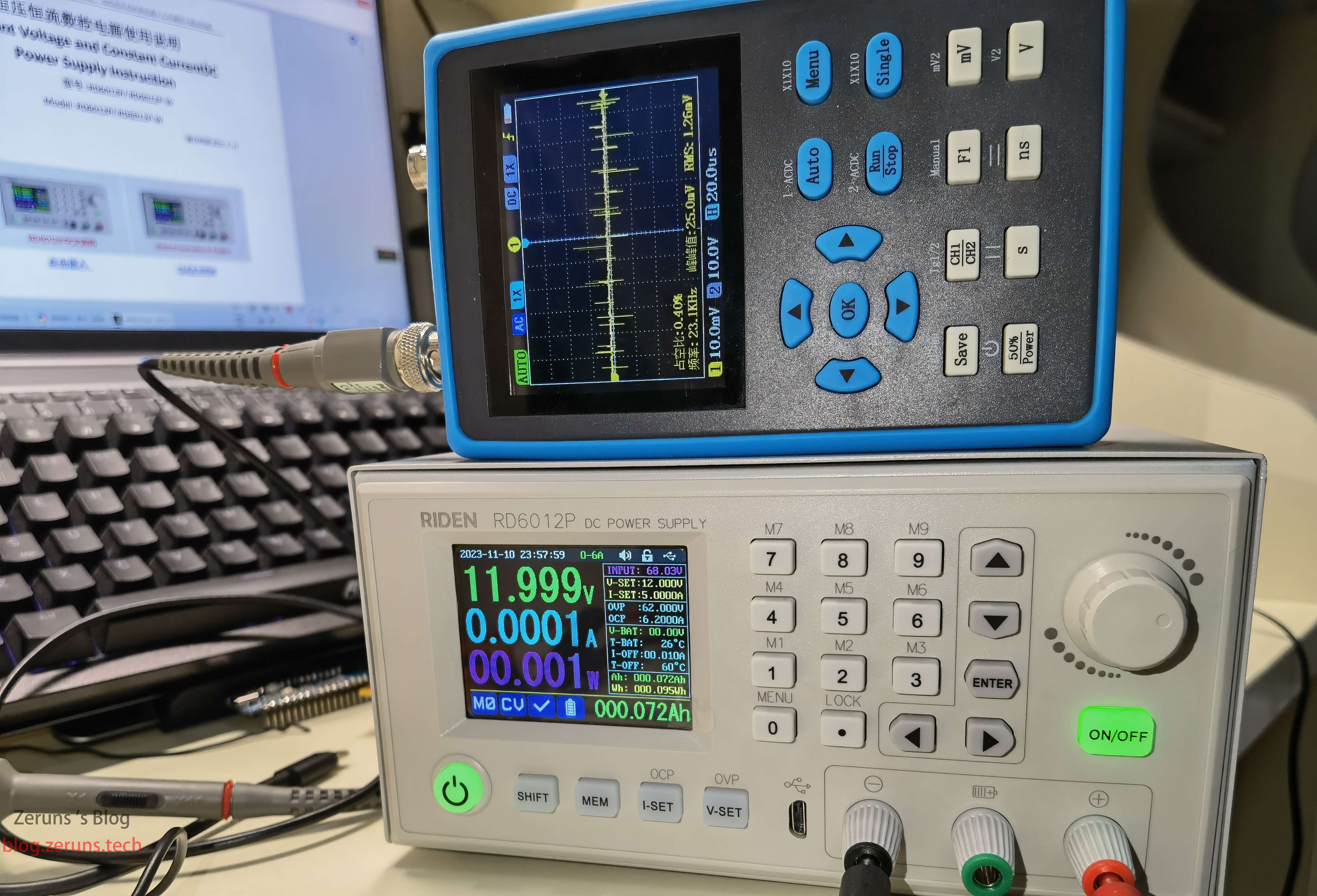
No-load ripple at 12V output: peak-to-peak ~25mV, average ~1.25mV—good performance.
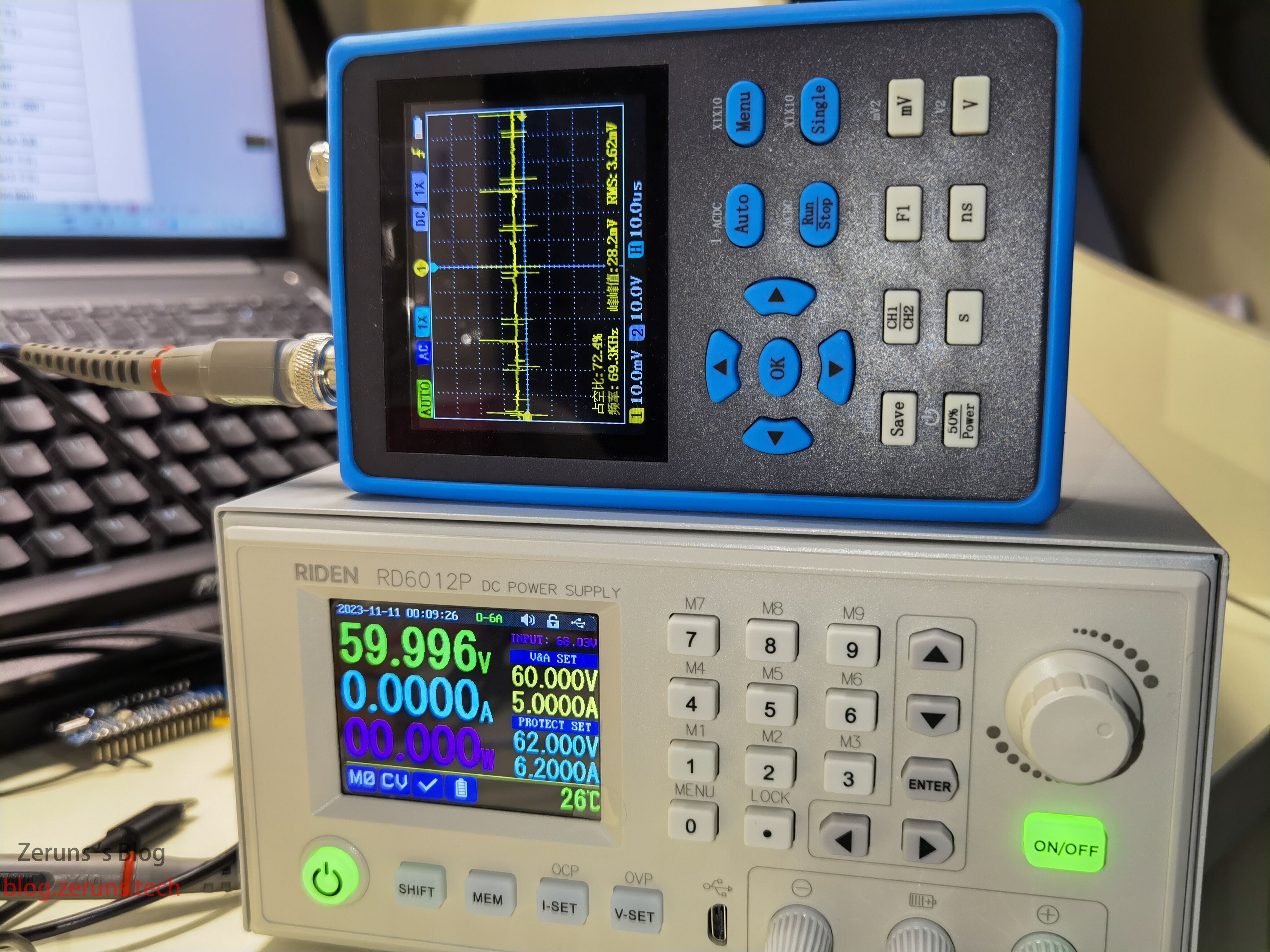
No-load ripple at 60V output: peak-to-peak ~28.2mV, average ~3.62mV—excellent, considering the high voltage.
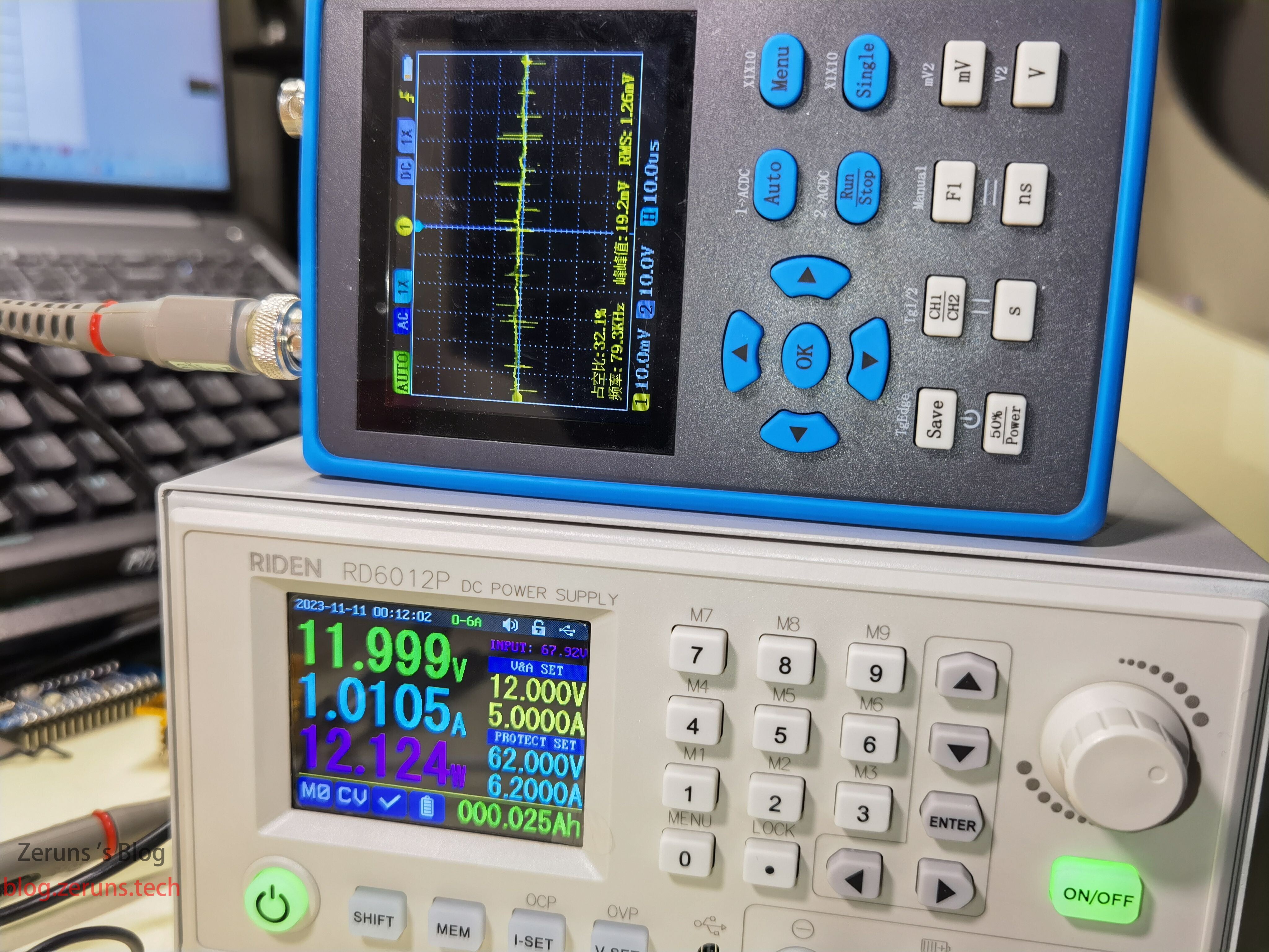
With 12Ω resistive load, 12V/1A output: ripple ~19.2mVpp, average ~1.26mV—excellent.
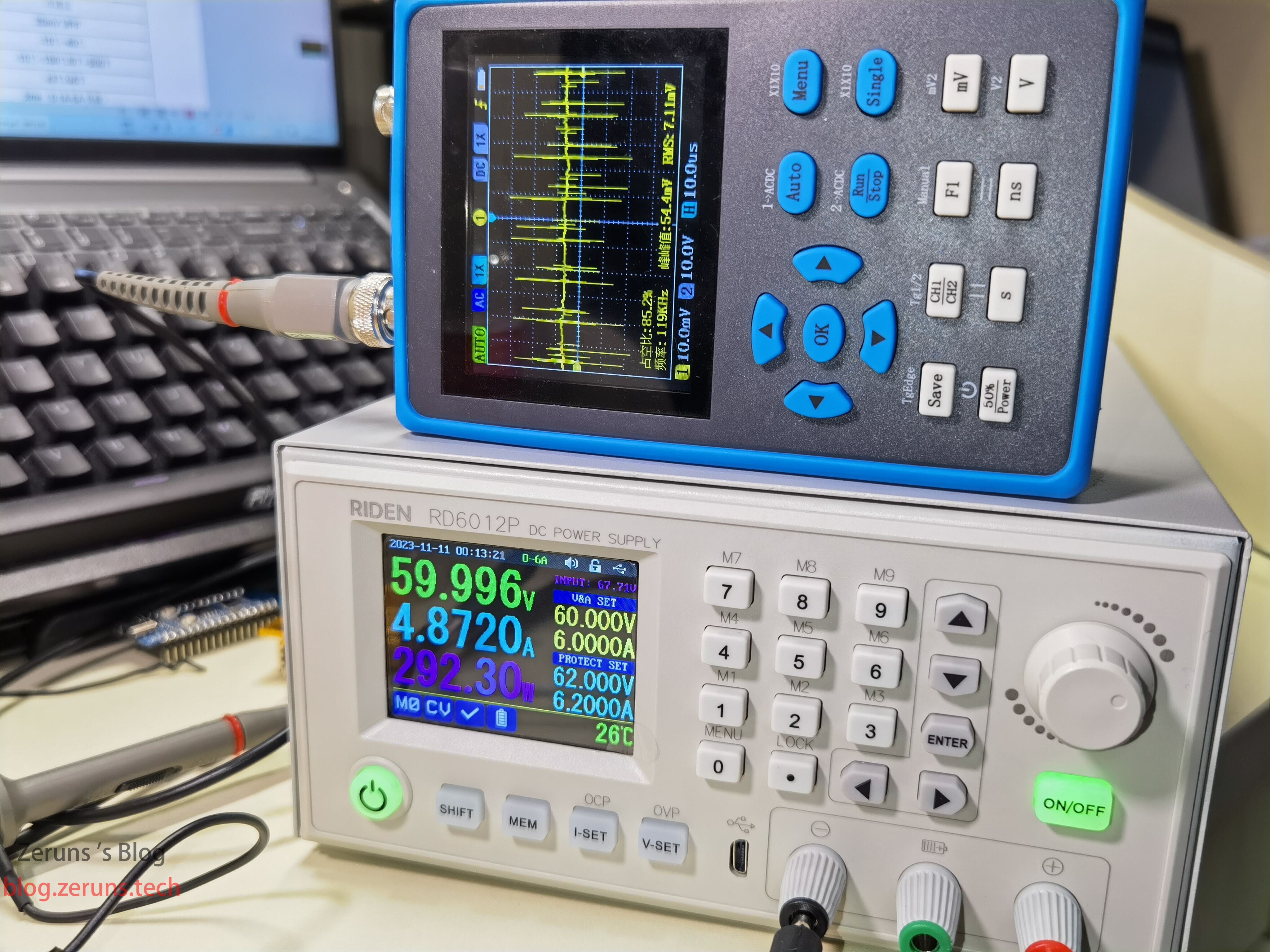
With 12Ω load, 60V/4.8A output: ripple ~54.4mVpp, average ~7.11mV—still good performance under high load.
Recommended Articles
- LONVIE Hot Air Gun and Soldering Iron Combo Station Unboxing Review: https://blog.zeruns.com/archives/711.html
- UNI-T / Toky Adjustable Power Supply X08P3010 Unboxing and Teardown: https://blog.zeruns.com/archives/698.html
- Affordable and High-Value VPS/Cloud Server Recommendations: https://blog.zeruns.com/archives/383.html
- Minecraft Server Setup Guide: https://blog.zeruns.com/tag/mc/
- Orange Pi 3B (RK3566) Development Board Unboxing Review: https://blog.zeruns.com/archives/729.html
- Open-Source EG1164 High-Power Synchronous Rectified Boost Module, Up to 97% Efficiency: https://blog.zeruns.com/archives/730.html