I’m an electronics hobbyist, and I’m currently trying to build the driver circuit for an ultrasonic atomizer. Before getting started, I’ve been studying this driver circuit a bit, and my conclusions so far are as follows:
-
An ultrasonic atomizer works by using a piezoelectric ceramic disc to vibrate rapidly and break water into tiny mist droplets, thereby producing mist;
-
There are currently two types of atomizing discs on the market: ultrasonic atomizing discs and microporous atomizing discs. The difference between them is that the former operates at high frequency, while the latter has a lower frequency.
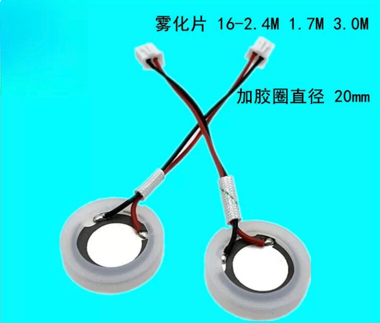
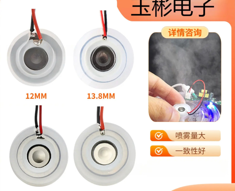
- To drive the atomizing disc, an oscillator circuit is needed to generate an AC signal.
The issue I’m currently stuck on is this oscillator/driver circuit. I’ve been looking up information online and in discussion groups, and my current understanding is as follows:
-
The two most basic components of an oscillator circuit are the inductor and capacitor, which exchange stored energy and potential energy. During this process, the polarity of the inductor reverses, and this is the key to generating AC;
-
Based on what I currently want to build, I plan to use a three-point capacitive oscillator circuit (below is the schematic I sketched out; the specific component selection and parameters have not been finalized yet)
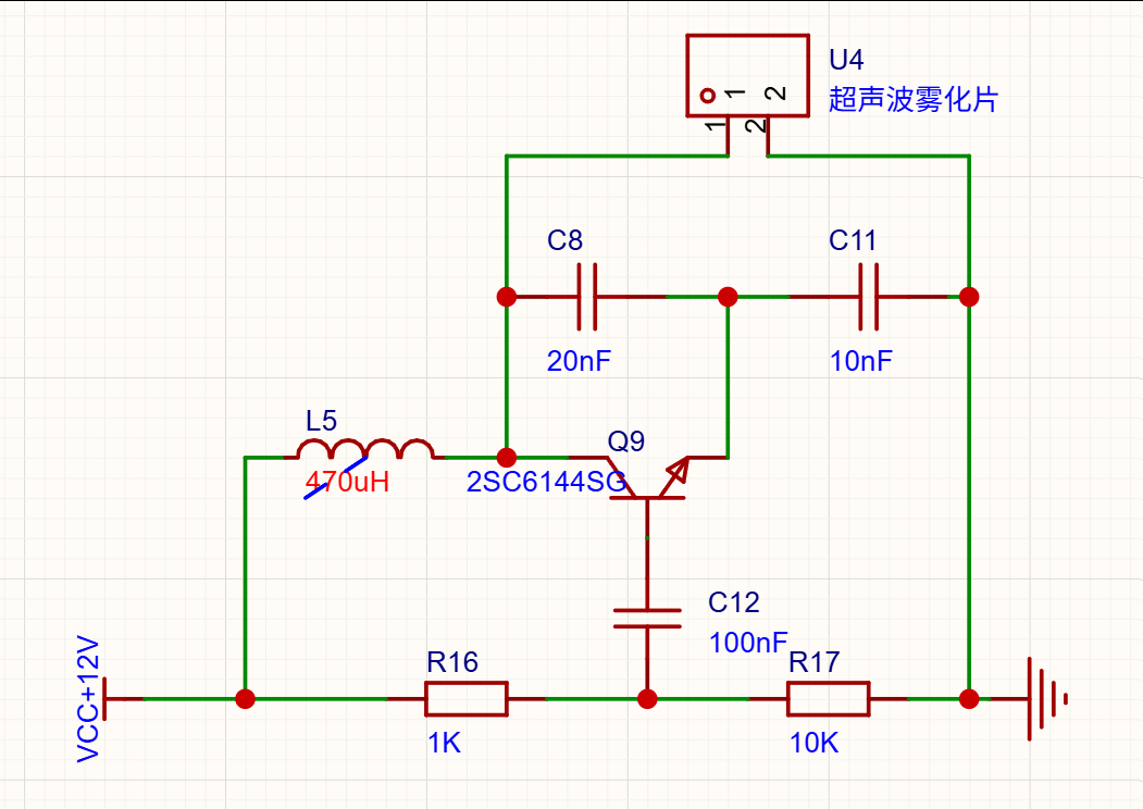
For component selection, I first determined that the atomizing disc frequency is 1.7 MHz, then calculated the value of  backwards from the desired frequency. My result was 9.36×10^-8.
-
A (amplification factor) * β (feedback coefficient) > 1. In the materials I looked up, it says 3∼5. Most sources write |A*β| as being in this range, but since our goal is to generate oscillation, it should be a positive value, producing an amplifying effect.
-
The capacitance values are the combined capacitance of C8, C11, and the atomizing disc. The β feedback coefficient is

-
The base and the center tap of the bias resistor are equivalent to AC ground, so a capacitor needs to be connected in parallel.
As the saying goes, it all makes sense when you read it, but falls apart as soon as you try to do it. I feel like I don’t really understand it that well from reading, and actually building it is even more difficult. The points I’m currently stuck on are:
-
First, apart from the capacitance value of the atomizing disc, which I can calculate directly, how do I calculate the values of the other two capacitors? For now, I only found an empirical rule for the product of A and β, and I don’t know exactly what the value should be, so I can’t work backward to determine the specific values of C8 and C11. I also can’t calculate the inductance value.
-
What criteria should be used when selecting the capacitor for AC grounding at the base?
-
Is this driver circuit correct? If I want to control the mist output, could I add a power MOSFET at the front end of the driver circuit’s GND and use a square wave to control the average power, thereby indirectly controlling the mist output?
-
Could experienced folks take a look and tell me whether the circuit is correct?
I hope experienced folks can take a look, give me some comments, and let me know whether my line of thinking is correct