基于CH32V307VCT6的智能电子负载开源,嵌入式大赛作品开源,含原理图、PCB、程序源码、作品报告。
2023年嵌入式芯片与系统设计竞赛应用赛道,国二作品。
用半个月时间在之前做的合泰版的电子负载的基础上改的,移植了程序到CH32单片机,并使用了RT-Thread系统,优化了一下代码,赶工做出来,做得很一般,勿喷。
作品演示视频:https://www.bilibili.com/video/BV1Zu4y1m7Zd/
基于HT32F52352的智能电子负载开源,合泰杯作品开源:https://blog.zeruns.com/archives/784.html
本开源作品仅供参考学习,不建议复刻,立创开源平台上有更多更好的更完善的电子负载开源作品!
本项目的立创开源平台开源链接:https://url.zeruns.com/Et4x4
电子/单片机技术交流群:2169025065
沁恒官网可以免费申请开发板样品:https://url.zeruns.com/h9a99
什么是电子负载
电子负载是一种电子设备,用于模拟真实负载环境,以测试电源或电子电路的性能。比起使用大功率可调电阻或者电炉丝等传统的无源负载,电子负载具有参数可调,使用方便等诸多优势。无论是专业的电子工程项目开发还是业余的电子爱好者,电子负载仪都是必备的设备之一。
电子负载从测试电源的种类来分可以分为交流电子负载和直流电子负载。从功能上划分常见的有恒流、恒压、恒阻、恒功率四种类型。因为我们常见的大多数电源都是恒压直流电源。测试这类电源时,主要测试的是其电流输出能力。所以大多数的应用场景中,直流恒流电子负载是最为常见的类型。而电子负载从控制方式上划分则又可以分为数控和模拟两种类型。相较于使用纯模拟电路控制的电子负载,数控电子负载使用数字控制,在参数调节上更为直观,而且功能丰富、扩充简单,还可以方便的实现测试的自动化。
项目简介
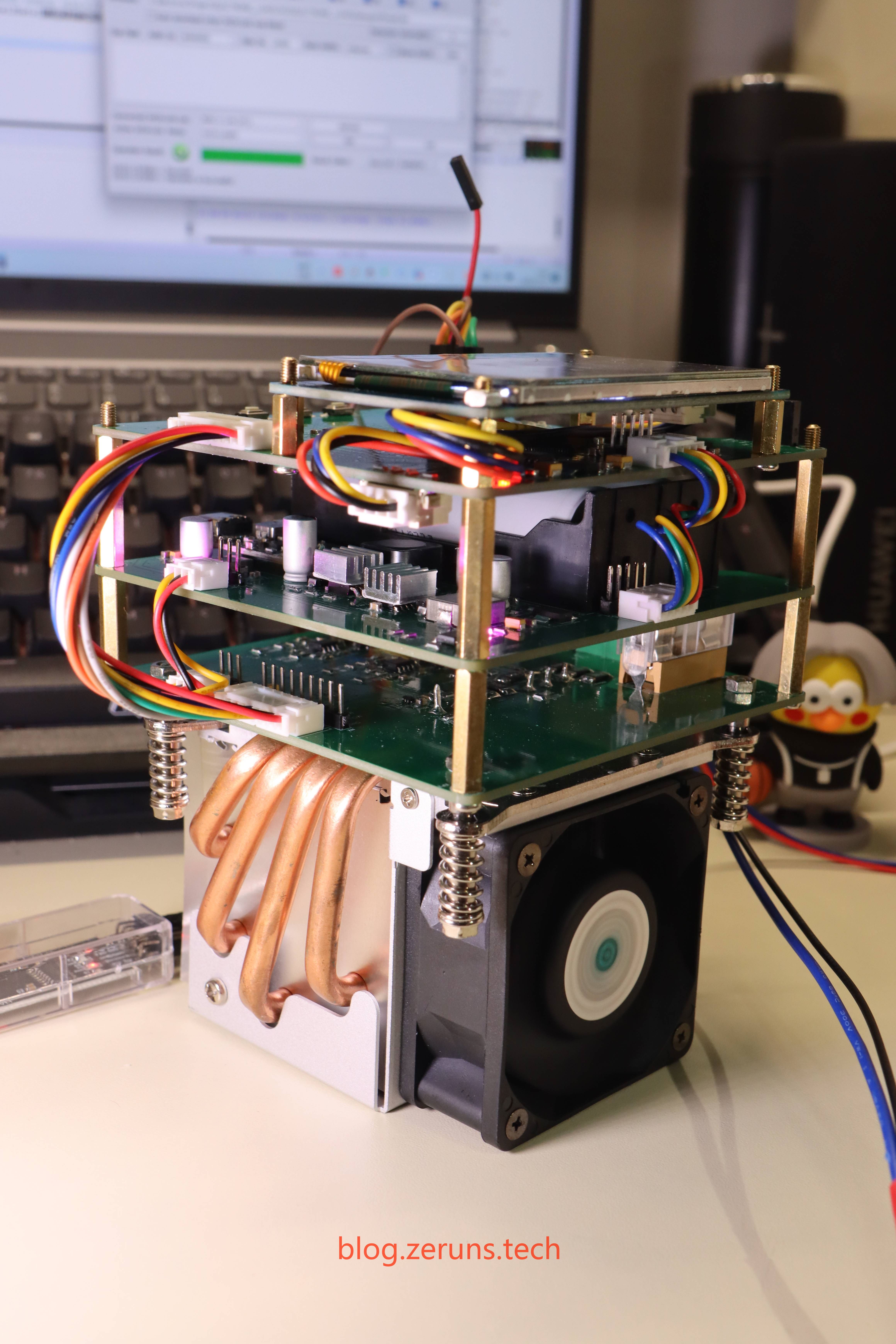
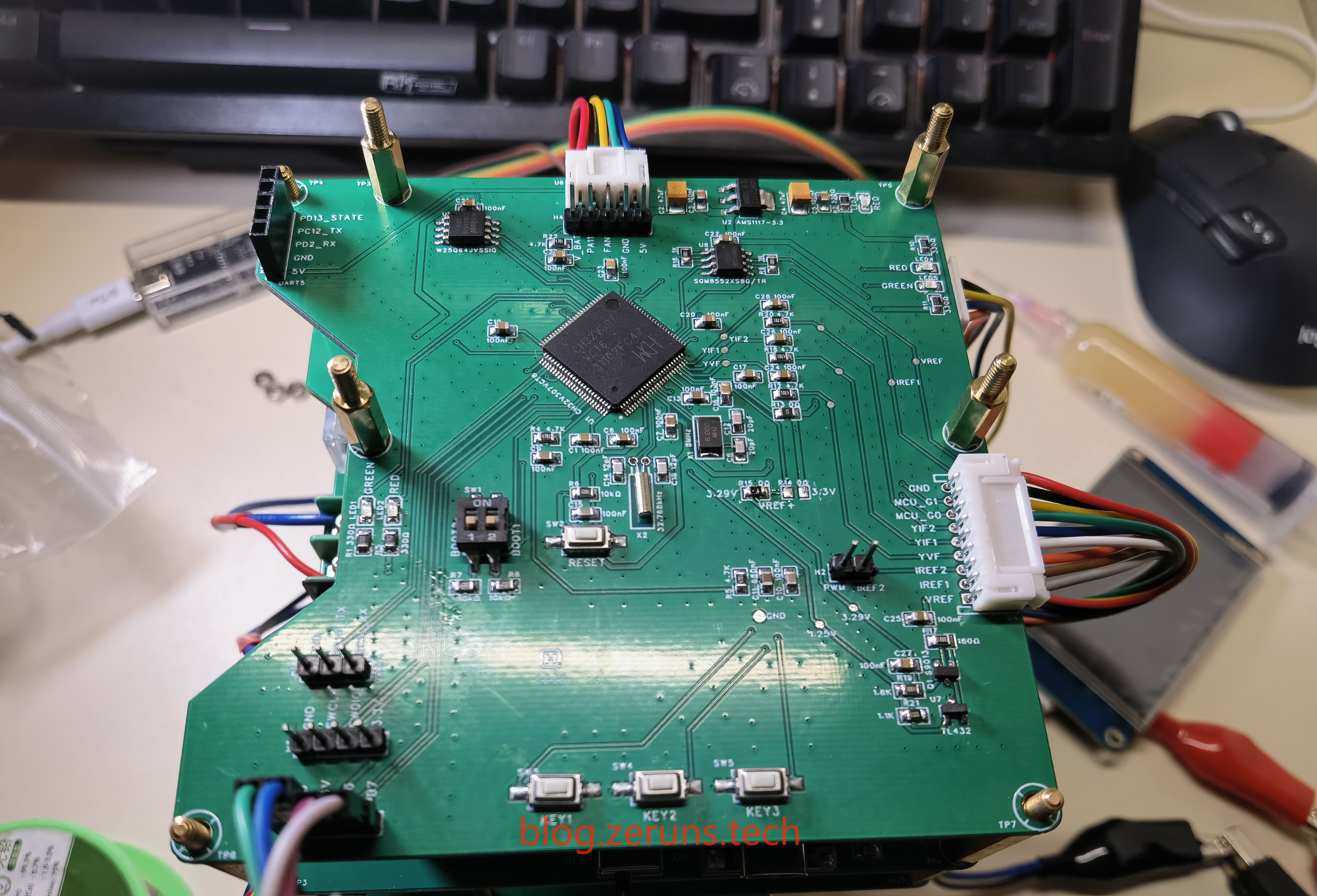
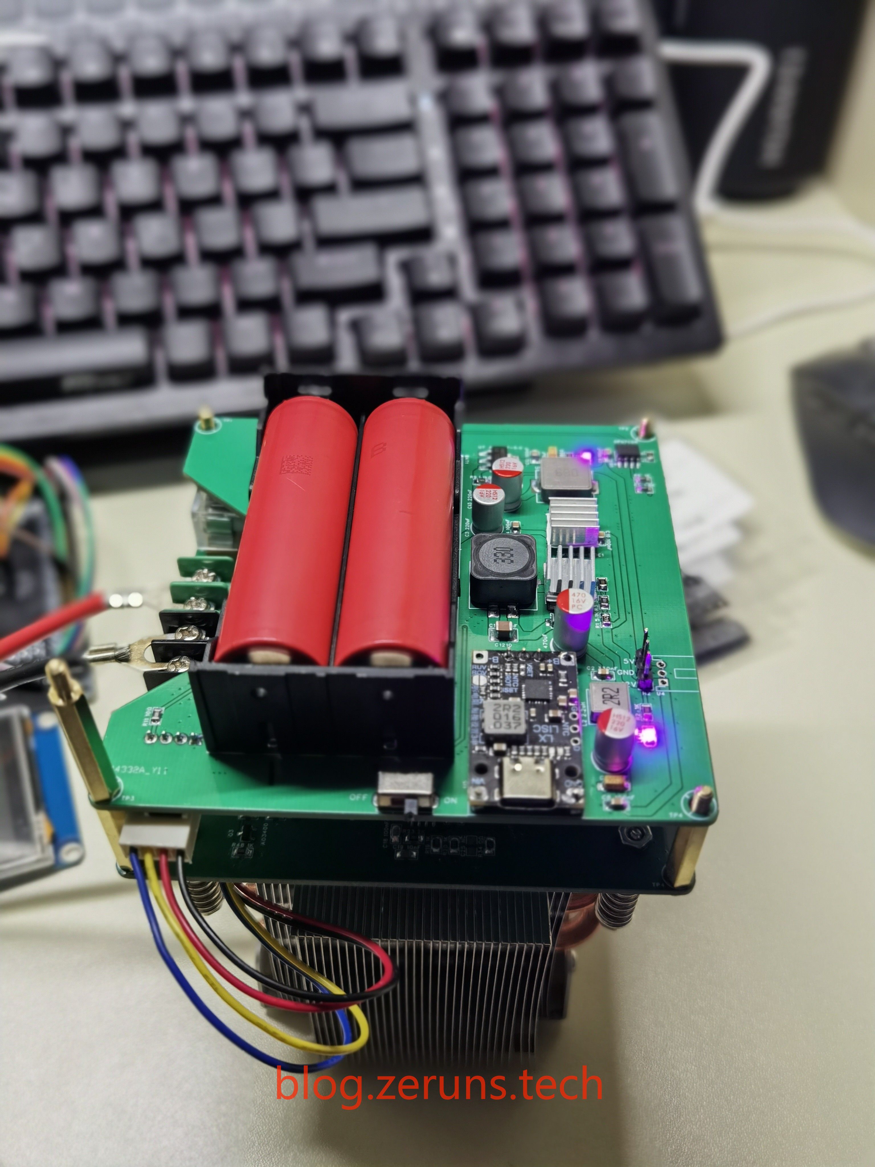
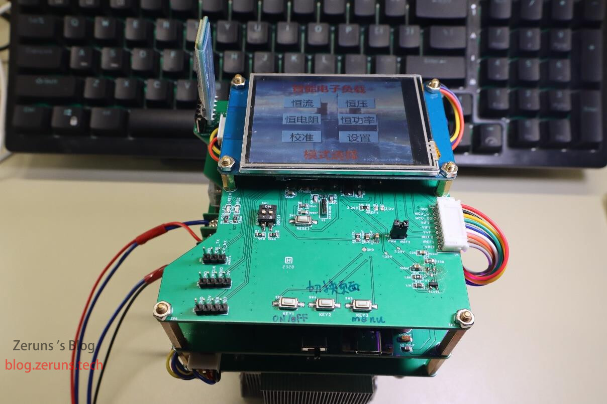
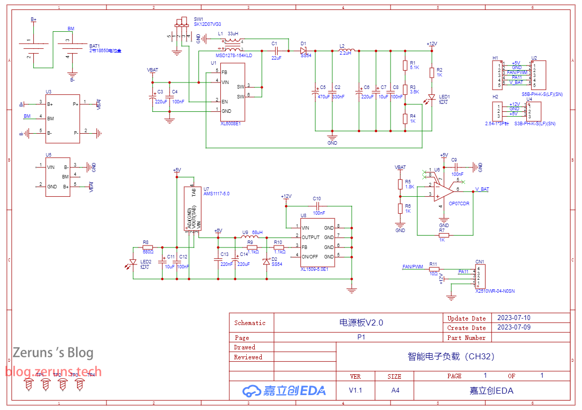
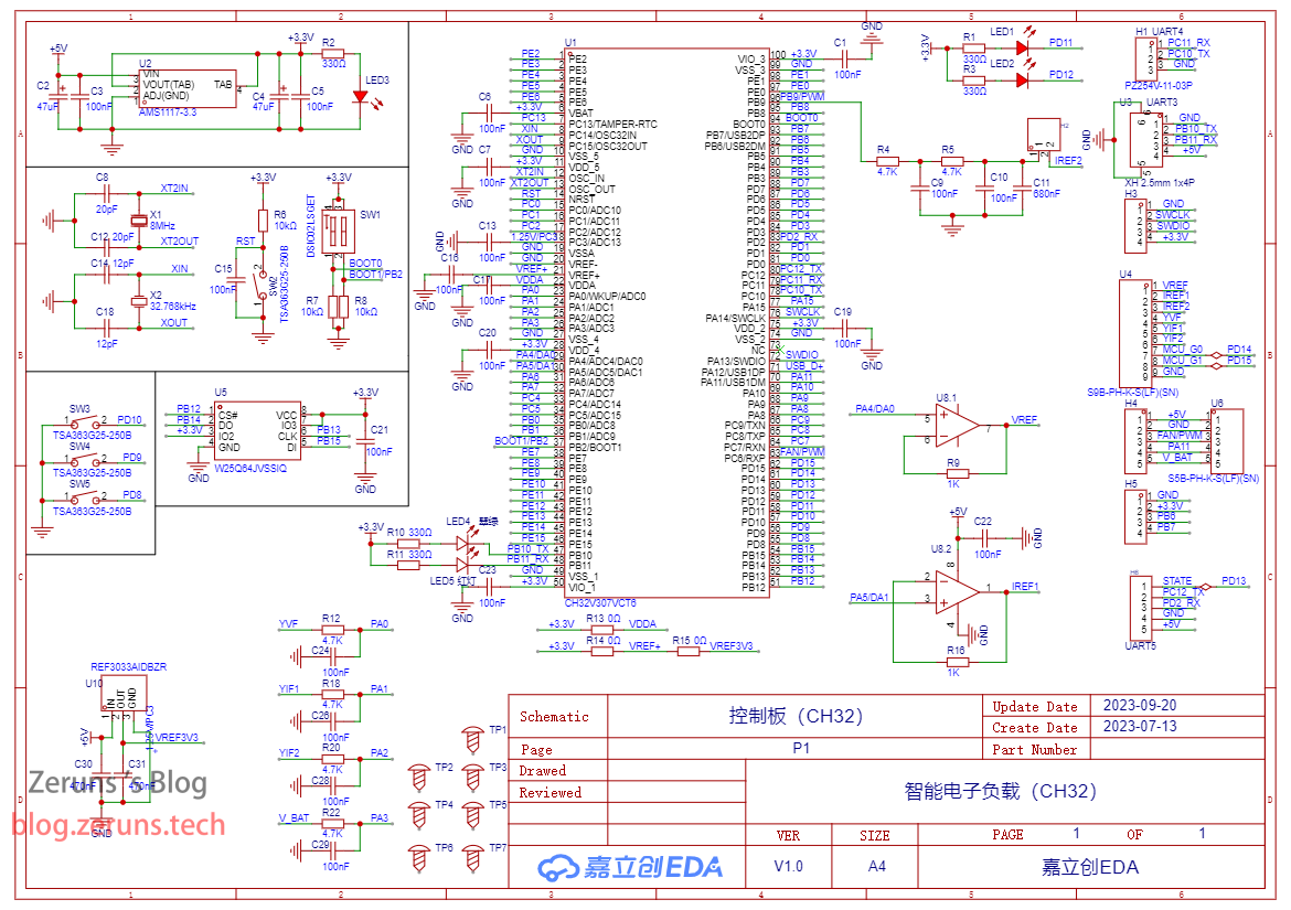
本作品采用 CH32V307VCT6 沁恒单片机作为主控芯片设计的电子负载,供电方式由18650锂电池供电,方便携带。
控制方式为通过单片机DAC输出一个直流电压作为参考电压给到运放与电流/电压采样放大后的电压做比较,运放输出控制MOS管,从而实现恒压/恒流。
触控屏用的是陶晶驰的2.8寸串口屏,型号为:TJC3224T028_011R。
散热器用的是2U服务器的1356/1366针散热器,侧吹的。
项目程序使用RT-Thread Studio开发。电路设计用的立创EDA软件。
最大输入电压电流为100V/10A,最大功率200W。
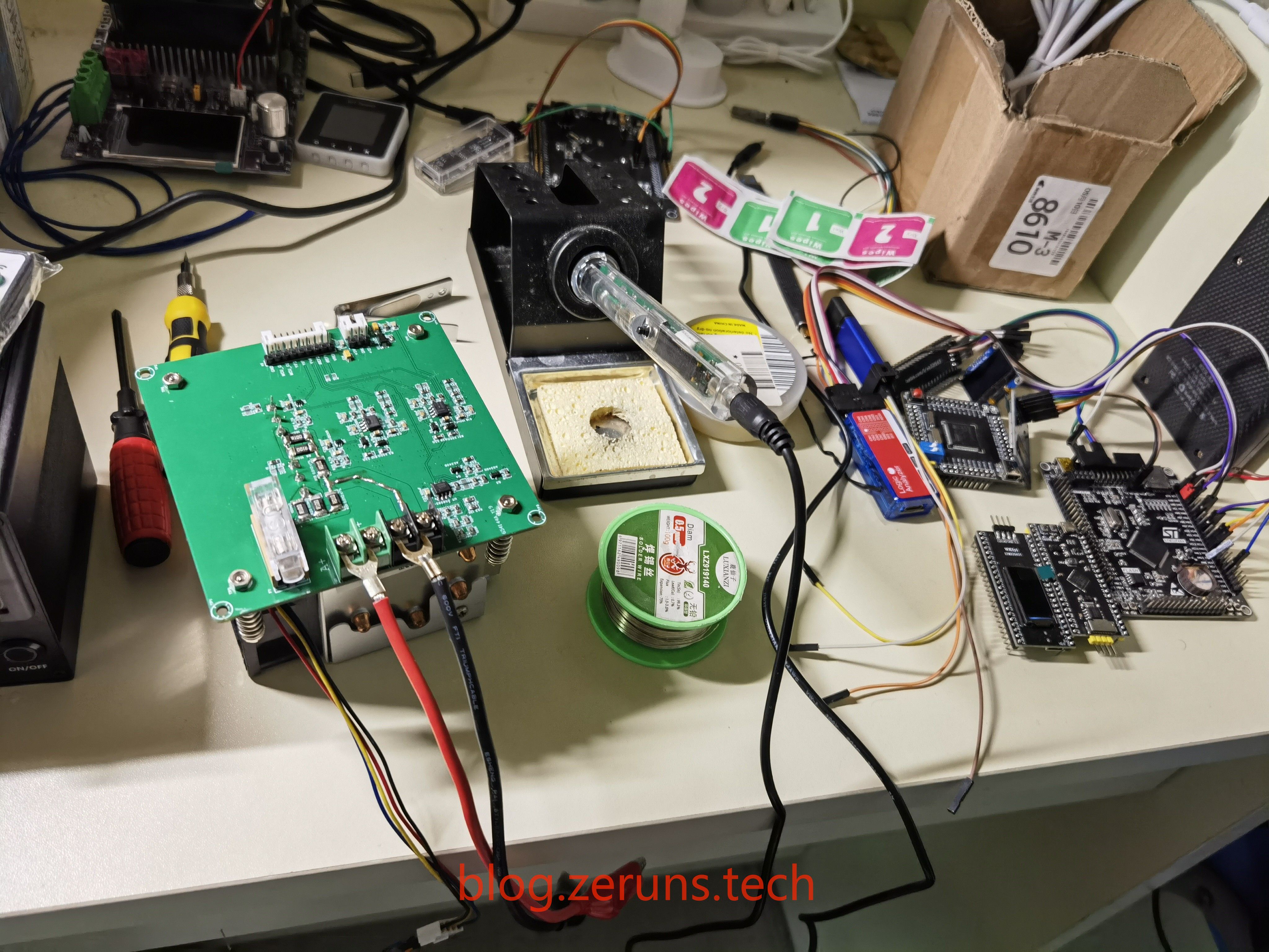
实物图
当时没拍多少照片,就找到这几张了,可以去看看演示视频。
资料下载地址
下面链接中的资料有:电路原理图、立创EDA工程文件、PCB制板文件、程序源码、串口屏工程文件、芯片手册。
123云盘不限速下载地址:https://www.123pan.com/ps/2Y9Djv-6NevH.html
百度网盘下载地址:https://pan.baidu.com/s/17YSlBZ6F1M18k7JGa7FlVA?pwd=buxx 提取码:buxx
元件购买地址
- CH32V307VCT6芯片:https://s.click.taobao.com/T8MSZot
- CH32V307VCT6开发板:https://s.click.taobao.com/2JBSZot
- INA199A1芯片:https://s.click.taobao.com/XLuweot
- 0805贴片电阻样品本:https://s.click.taobao.com/p8YSGpt
- 0805贴片电容样品本:https://u.jd.com/9uvZoBd
- XL1509芯片:https://s.click.taobao.com/DOcRZot
- 串口屏:https://s.click.taobao.com/pyzleot
建议在立创商城里购买元器件:https://activity.szlcsc.com/invite/D03E5B9CEAAE70A4.html
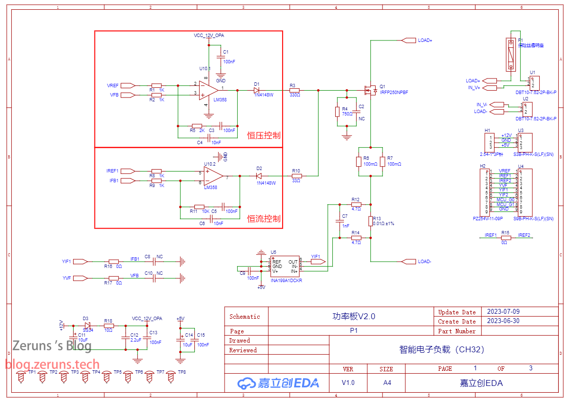
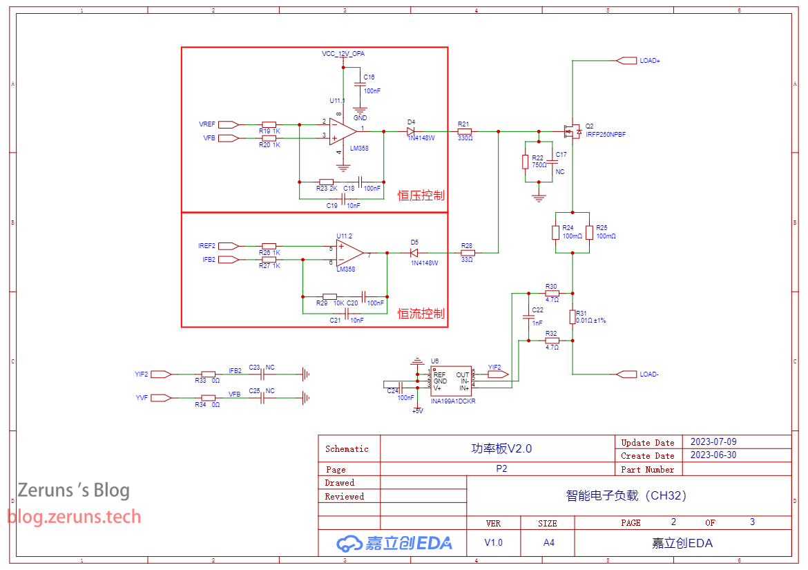
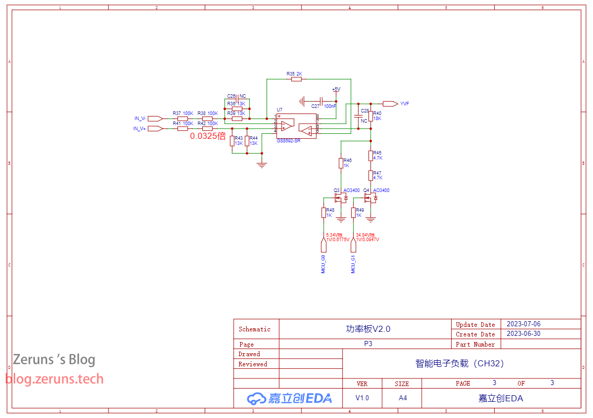
原理图
功率板
电源板
控制板
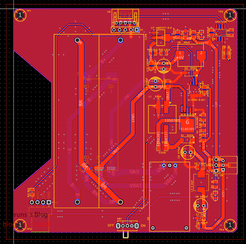
PCB
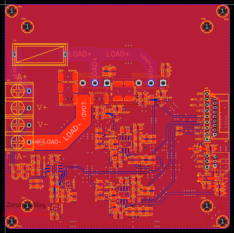
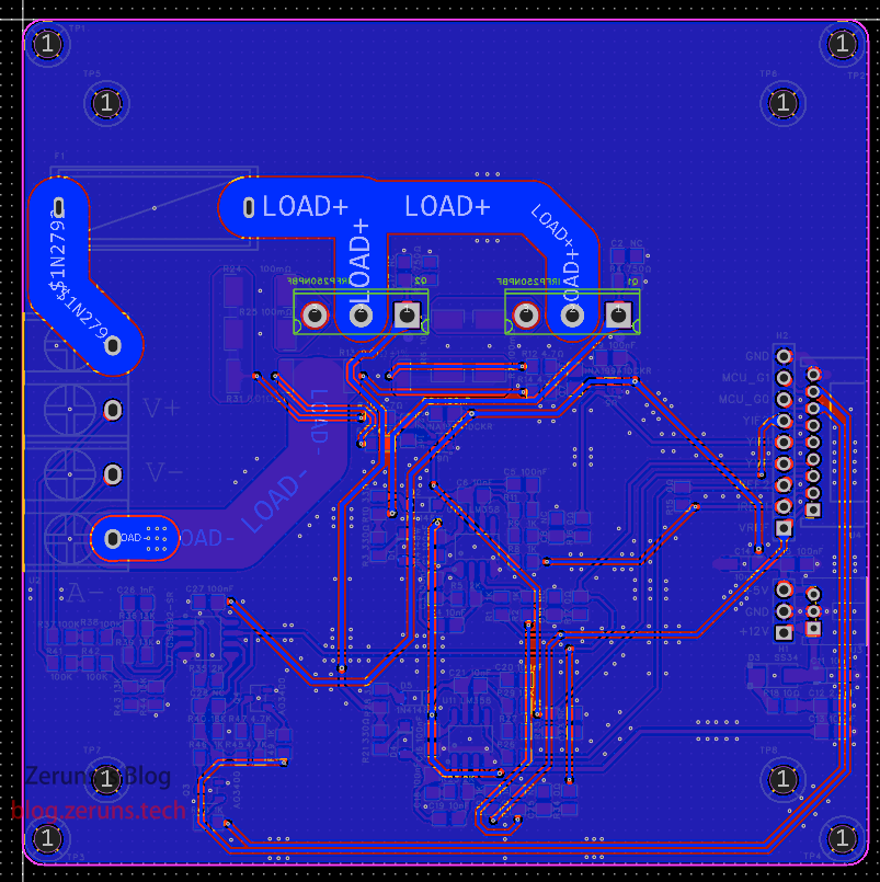
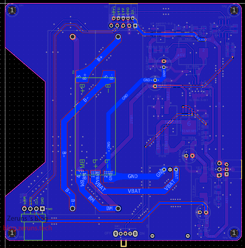
功率板
顶层
底层
电源板
顶层
底层
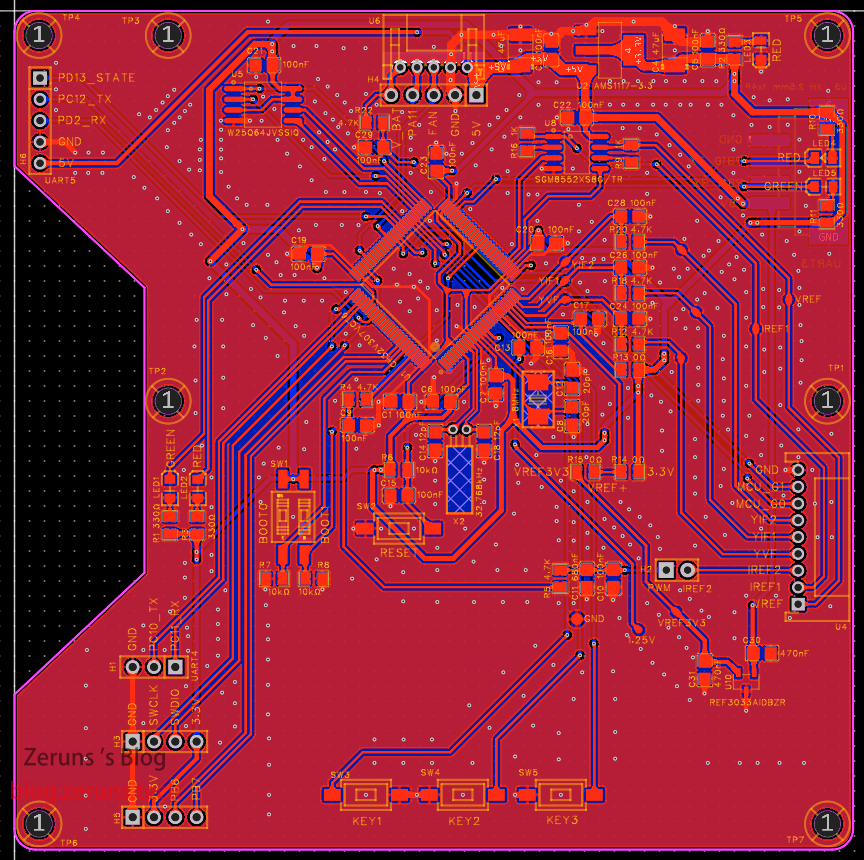
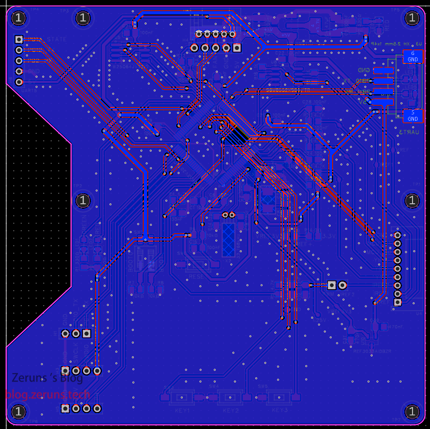
控制板
顶层
底层
其他开源项目推荐
- 做了个三相电量采集器开源出来,可以方便监测家里用电情况:https://blog.zeruns.com/archives/771.html
- 移植好U8g2图形库的STM32F407标准库工程模板:https://blog.zeruns.com/archives/722.html
- 沁恒CH32V307VCT6最小系统板开源:https://blog.zeruns.com/archives/726.html
- LM25118自动升降压可调DCDC电源模块:https://blog.zeruns.com/archives/727.html
- EG1164大功率同步整流升压模块开源,最高效率97%:https://blog.zeruns.com/archives/730.html
- 基于合宙Air700E的4G环境监测节点(温湿度、气压等数据),通过MQTT上传阿里云物联网平台:https://blog.zeruns.com/archives/747.html
主要代码
main.c文件
/********************************** (C) COPYRIGHT *******************************
* File Name : main.c
* Author : WCH
* Version : V1.0.0
* Date : 2021/06/06
* Description : Main program body.
* Copyright (c) 2021 Nanjing Qinheng Microelectronics Co., Ltd.
* SPDX-License-Identifier: Apache-2.0
* https://blog.zeruns.com
*******************************************************************************/
#include "ch32v30x.h"
#include <rtthread.h>
#include <rtdevice.h>
#include <stdlib.h>
#include <rthw.h>
#include "drivers/pin.h"
#include <board.h>
#include <rtdbg.h>
#include <u8g2_port.h>
#include <qpid.h>
#include "USART.h"
#include "KEY.h"
#include "DAC.h"
#include "PWM.h"
/* Global typedef */
/* Global define */
#define WDT_DEVICE_NAME "wdt" /* 看门狗设备名称 */
static rt_device_t wdg_dev; /* 看门狗设备句柄 */
/* ADC参考电压 */
#define VREF 3.3
/* 电源电压 */
#define VCC 3.3
/* 补偿校准数据 */
#define V0_COMP 1.000 // 0.0325倍电压档位
#define V1_COMP 1.000 // 0.0947倍电压档位
#define V2_COMP 1.000 // 0.6175倍电压档位
#define YIF1_COMP 1.00 // MOS管1電流採樣補償
#define YIF2_COMP 1.00 // MOS管2電流採樣補償
#define DAC1_COMP 1.00 // DAC1(VREF)输出补偿系数
#define IREF2_COMP 1.00 // IREF2输出补偿系数
#define DAC2_COMP 1.00 // DAC2(IREF1)输出补偿
/* ADC採樣平均值計算次數 */
#define ADC_count 3
/* 一阶低通滤波器滤波系数*/
#define dPower1 0.5
/* 引脚编号,通过查看驱动文件drv_gpio.c确定 */
#define OLED_I2C_PIN_SCL 22 //PB6
#define OLED_I2C_PIN_SDA 23 //PB7
#define LED2 59 //PD11
#define LED1 60 //PD12
#define MCU_G0 62 //PD14
#define MCU_G1 63 //PD14
/* Global Variable */
u8g2_t u8g2; // u8g2的结构体变量
rt_uint16_t AD_Value[4]; //ADC采样数据
// 定义模式页面的枚举变量
enum mode_type
{
menu = 0, // 菜单
CC, // 恒流
CV, // 恒压
CR, // 恒阻
CW // 恒功率
};
volatile uint8_t Eload_Out = 0; // 电子负载输出开启/关闭状态
volatile uint8_t mode = menu; // 当前模式
volatile uint8_t voltage_dw = 0; // 电压采样档位,0为0.0325倍,2为0.6175倍,1为0.0947倍
volatile double YVF, YIF1, YIF2, YIF, VBAT; // 当前电压电流
volatile double ISET, VSET, RSET, PSET; // 电流、电压、电阻、功率设置值
volatile uint32_t YVF_SUM, YIF1_SUM, YIF2_SUM, VBAT_SUM; // 电压电流算平均值用的计算总和
volatile uint8_t AVG_count = 0; // 电流平均值计算累加计数值
volatile uint8_t YVF_AVG_count = 0; // 电压平均值计算累加计数值
volatile uint8_t VBAT_count = 0; // 电池电压平均值计算累加计数值
volatile uint8_t Key_ONOFF = 0; // 电子负载开启关闭按钮是否被按下状态
static qpid_t qpid_CC; // PID控制数据指针
static qpid_t qpid_CV; // PID控制数据指针
static qpid_t qpid_CR; // PID控制数据指针
static qpid_t qpid_CW; // PID控制数据指针
static double I_SET, V_SET, R_SET, P_SET;
/* 函数声明 */
void OLED_Init(void);
static int IWDG_Init();
static void thread1_sysLED_entry(void *parameter);
static void thread2_OLED_entry(void *parameter);
static void thread3_ADC_entry(void *parameter);
static void thread4_HMI_GetDate_entry(void *parameter);
static void thread5_ONOFF_entry(void *parameter);
static void thread7_HMI_Display_entry(void *parameter);
static void thread8_FAN_entry(void *parameter);
static void thread9_CWCR_entry(void *parameter);
static void thread10_BlueTooth_entry(void *parameter);
void CW_mode(void);
void CR_mode(void);
void key123(void);
void Thread_Init(void);
void SYS_Init(void);
void PID(void);
/*********************************************************************
* @fn main
*
* @brief Main program.
*
* @return none
*/
int main(void)
{
rt_kprintf("MCU: CH32V307\n");
rt_kprintf("SysClk: %dHz\n", SystemCoreClock);
SYS_Init();
while (1)
{
// 过流和过功率保护
if (YIF > 10 | YVF * YIF > 300)
{
if (Eload_Out == 1)
{
Key_ONOFF = 1;
}
}
rt_thread_mdelay(20);
}
}
/* 系统初始化 */
void SYS_Init(void)
{
IWDG_Init(); // 初始化看门狗
UART_Init(); // 串口3初始化
HMILCD_Send("page 0"); // 切到启动页
Dac_Init(); // 初始化DAC
PWM_Init(); // 初始化PWM
rt_pin_mode(MCU_G0, PIN_MODE_OUTPUT); // 设置IO口为输出模式
rt_pin_mode(MCU_G1, PIN_MODE_OUTPUT);
rt_pin_write(MCU_G0, PIN_LOW); // 输出低电平
rt_pin_write(MCU_G1, PIN_LOW);
Thread_Init(); // 创建线程
}
/* 线程初始化 */
void Thread_Init(void)
{
rt_thread_t tid = NULL; //定义一个线程控制块指针
/* 创建线程 */
tid = rt_thread_create("SYS_LED", thread1_sysLED_entry, NULL, 512, 30, 5);
//创建一个名为SYS_LED的线程,入口函数为thread1_sysLED_entry,参数为NULL,栈大小为256字节,优先级为30,时间片为5个tick
if (tid != RT_NULL) // 判断线程是否创建成功
{
if (rt_thread_startup(tid) == RT_EOK) // 启动线程
LOG_D("thread sysLED create success");
}
else
{
LOG_E("thread1 sysLED create failed...");
}
/*
tid = rt_thread_create("OLED_Display", thread2_OLED_entry, NULL, 2048, 25, 30);
if (tid != RT_NULL)
{
if (rt_thread_startup(tid) == RT_EOK) // 启动线程
LOG_D("thread2 OLED create success");
}
else
{
LOG_E("thread2_OLED create failed...");
}*/
tid = rt_thread_create("ADC", thread3_ADC_entry, NULL, 1536, 18, 30);
if (tid != RT_NULL)
{
if (rt_thread_startup(tid) == RT_EOK) // 启动线程
LOG_D("thread3 ADC create success");
}
else
{
LOG_E("thread3 ADC create failed...");
}
tid = rt_thread_create("HMI_GetDate", thread4_HMI_GetDate_entry, NULL, 2048, 23, 30);
if (tid != RT_NULL)
{
if (rt_thread_startup(tid) == RT_EOK) // 启动线程
LOG_D("thread4 HMI_GetDate create success");
}
else
{
LOG_E("thread4 HMI_GetDate create failed...");
}
tid = rt_thread_create("ONOFF", thread5_ONOFF_entry, NULL, 1024, 15, 25);
if (tid != RT_NULL)
{
if (rt_thread_startup(tid) == RT_EOK) // 启动线程
LOG_D("thread5 ONOFF create success");
}
else
{
LOG_E("thread5 ONOFF create failed...");
}
tid = rt_thread_create("KEY", thread6_KEY_entry, NULL, 512, 20, 20);
if (tid != RT_NULL)
{
if (rt_thread_startup(tid) == RT_EOK) // 启动线程
LOG_D("thread6 KEY create success");
}
else
{
LOG_E("thread6 KEY create failed...");
}
tid = rt_thread_create("HMI_Display", thread7_HMI_Display_entry, NULL, 1024, 25, 30);
if (tid != RT_NULL)
{
if (rt_thread_startup(tid) == RT_EOK) // 启动线程
LOG_D("thread7 HMI_Display create success");
}
else
{
LOG_E("thread7 HMI_Display create failed...");
}
tid = rt_thread_create("FAN", thread8_FAN_entry, NULL, 512, 26, 15);
if (tid != RT_NULL)
{
if (rt_thread_startup(tid) == RT_EOK) // 启动线程
LOG_D("thread8 FAN create success");
}
else
{
LOG_E("thread8 FAN create failed...");
}
tid = rt_thread_create("CWCR", thread9_CWCR_entry, NULL, 512, 19, 15);
if (tid != RT_NULL)
{
if (rt_thread_startup(tid) == RT_EOK) // 启动线程
LOG_D("thread9 CWCR create success");
}
else
{
LOG_E("thread9 CWCR create failed...");
}
tid = rt_thread_create("BlueTooth", thread10_BlueTooth_entry, NULL, 2048, 23, 30);
if (tid != RT_NULL)
{
if (rt_thread_startup(tid) == RT_EOK) // 启动线程
LOG_D("thread10 BlueTooth create success");
}
else
{
LOG_E("thread10 BlueTooth create failed...");
}
}
/* 一阶低通滤波
* 返回值:iData 经过一阶滤波后的采样值 */
double lowV1(double com1)
{
static double iLastData1; //上一次值
double iData1; //本次计算值
iData1 = (com1 * dPower1) + (1 - dPower1) * iLastData1; //计算
iLastData1 = iData1; //存贮本次数据
return iData1; //返回数据
}
double lowV2(double com1)
{
static double iLastData2; //上一次值
double iData1; //本次计算值
iData1 = (com1 * dPower1) + (1 - dPower1) * iLastData2; //计算
iLastData2 = iData1; //存贮本次数据
return iData1; //返回数据
}
u16 lowV3(u16 com1)
{
static u16 iLastData3; //上一次值
u16 iData1; //本次计算值
iData1 = (com1 * dPower1) + (1 - dPower1) * iLastData3; //计算
iLastData3 = iData1; //存贮本次数据
return iData1; //返回数据
}
u16 lowV4(u16 com1)
{
static u16 iLastData3; //上一次值
u16 iData1; //本次计算值
iData1 = (com1 * 0.1) + (1 - 0.1) * iLastData3; //计算
iLastData3 = iData1; //存贮本次数据
return iData1; //返回数据
}
static void idle_hook(void)
{
/* 在空闲线程的回调函数里喂狗 */
rt_device_control(wdg_dev, RT_DEVICE_CTRL_WDT_KEEPALIVE, NULL);
//rt_kprintf("feed the dog!\n ");
}
static int IWDG_Init()
{
rt_err_t ret = RT_EOK;
rt_uint32_t timeout = 1; /* 溢出时间,单位:秒 */
/* 根据设备名称查找看门狗设备,获取设备句柄 */
wdg_dev = rt_device_find(WDT_DEVICE_NAME);
if (!wdg_dev)
{
rt_kprintf("find %s failed!\n", WDT_DEVICE_NAME);
return RT_ERROR;
}
/* 初始化设备 */
rt_device_init(wdg_dev);
/* 设置看门狗溢出时间 */
ret = rt_device_control(wdg_dev, RT_DEVICE_CTRL_WDT_SET_TIMEOUT, &timeout);
if (ret != RT_EOK)
{
rt_kprintf("set %s timeout failed!\n", WDT_DEVICE_NAME);
return RT_ERROR;
}
/* 启动看门狗 */
ret = rt_device_control(wdg_dev, RT_DEVICE_CTRL_WDT_START, RT_NULL);
if (ret != RT_EOK)
{
rt_kprintf("start %s failed!\n", WDT_DEVICE_NAME);
return -RT_ERROR;
}
/* 设置空闲线程回调函数 */
rt_thread_idle_sethook(idle_hook);
return ret;
}
/* 线程 1 的入口函数,系统运行状态灯闪烁 */
static void thread1_sysLED_entry(void *parameter)
{
/* LED1引脚为输出模式 */
rt_pin_mode(LED1, PIN_MODE_OUTPUT);
/* 默认低电平 */
rt_pin_write(LED1, PIN_LOW);
while (1)
{
/* 线程 1 采用低优先级运行,一直闪烁LED1 */
rt_pin_write(LED1, !rt_pin_read(LED1));
rt_thread_mdelay(500);
}
}
/* 线程 2 的入口函数,OLED屏显示信息 */
static void thread2_OLED_entry(void *parameter)
{
// Initialization
u8g2_Setup_ssd1306_i2c_128x64_noname_f(&u8g2, U8G2_R0, u8x8_byte_rtthread_hw_i2c, u8x8_gpio_and_delay_rtthread);
u8g2_InitDisplay(&u8g2);
u8g2_SetPowerSave(&u8g2, 0);
u8g2_InitDisplay(&u8g2);
u8g2_SetPowerSave(&u8g2, 0);
while (1)
{
char String[26];
u8g2_ClearBuffer(&u8g2);
u8g2_SetFont(&u8g2, u8g2_font_wqy15_t_chinese3); // 设置中文字符集
float V0 = AD_Value[0] * VREF / 4096.0;
sprintf(String, "AD0:%d V:%d.%d%d%d", AD_Value[0], (uint8_t) V0, (uint16_t)(V0 * 10.0) % 10,
(uint16_t)(V0 * 100.0) % 100 % 10, (uint16_t)(V0 * 1000.0) % 1000 % 100 % 10); // 格式化字符串输出到字符串变量
u8g2_DrawStr(&u8g2, 0, 15, String);
float V1 = AD_Value[1] * VREF / 4096.0;
sprintf(String, "AD1:%d V:%d.%d%d%d", AD_Value[1], (uint8_t) V1, (uint16_t)(V1 * 10.0) % 10,
(uint16_t)(V1 * 100.0) % 100 % 10, (uint16_t)(V1 * 1000.0) % 1000 % 100 % 10); // 格式化字符串输出到字符串变量
u8g2_DrawStr(&u8g2, 0, 31, String);
float V2 = AD_Value[2] * VREF / 4096.0;
sprintf(String, "AD2:%d V:%d.%d%d%d", AD_Value[2], (uint8_t) V2, (uint16_t)(V2 * 10.0) % 10,
(uint16_t)(V2 * 100.0) % 100 % 10, (uint16_t)(V2 * 1000.0) % 1000 % 100 % 10); // 格式化字符串输出到字符串变量
u8g2_DrawStr(&u8g2, 0, 47, String);
float V3 = AD_Value[3] * VREF / 4096.0;
sprintf(String, "AD3:%d V:%d.%d%d%d", AD_Value[3], (uint8_t) V3, (uint16_t)(V3 * 10.0) % 10,
(uint16_t)(V3 * 100.0) % 100 % 10, (uint16_t)(V3 * 1000.0) % 1000 % 100 % 10); // 格式化字符串输出到字符串变量
u8g2_DrawStr(&u8g2, 0, 63, String);
u8g2_SendBuffer(&u8g2); // 发送缓冲区数据
rt_thread_mdelay(100); // 延时100毫秒
}
}
/* 线程 3 的入口函数,ADC数据处理 */
static void thread3_ADC_entry(void *parameter)
{
RCC_APB2PeriphClockCmd(RCC_APB2Periph_GPIOA | RCC_APB2Periph_ADC1, ENABLE); //使能GPIOA时钟和ADC
RCC_AHBPeriphClockCmd(RCC_AHBPeriph_DMA1, ENABLE); //启用DMA1时钟
RCC_ADCCLKConfig(RCC_PCLK2_Div6); //ADC时钟分配配置,6分频(72Mhz/6=12Mhz),ADC时钟频率不能大于14Mhz
GPIO_InitTypeDef GPIO_InitStructure = { 0 }; //定义结构体配置GPIO
GPIO_InitStructure.GPIO_Pin = GPIO_Pin_0 | GPIO_Pin_1 | GPIO_Pin_2 | GPIO_Pin_3; //设置GPIO口
GPIO_InitStructure.GPIO_Mode = GPIO_Mode_AIN; //GPIO模式为模拟输入
GPIO_Init(GPIOA, &GPIO_InitStructure);
ADC_RegularChannelConfig(ADC1, ADC_Channel_0, 1, ADC_SampleTime_239Cycles5); //配置ADC规则组,在规则组的序列1写入通道0,采样时间55.5个周期
ADC_RegularChannelConfig(ADC1, ADC_Channel_1, 2, ADC_SampleTime_239Cycles5); //配置ADC规则组,在规则组的序列2写入通道1,采样时间55.5个周期
ADC_RegularChannelConfig(ADC1, ADC_Channel_2, 3, ADC_SampleTime_239Cycles5); //配置ADC规则组,在规则组的序列3写入通道2,采样时间55.5个周期
ADC_RegularChannelConfig(ADC1, ADC_Channel_3, 4, ADC_SampleTime_239Cycles5); //配置ADC规则组,在规则组的序列4写入通道3,采样时间55.5个周期
ADC_InitTypeDef ADC_InitStructure = { 0 };
ADC_InitStructure.ADC_Mode = ADC_Mode_Independent; //配置ADC为独立模式
ADC_InitStructure.ADC_ScanConvMode = ENABLE; //多通道模式下开启扫描模式
ADC_InitStructure.ADC_ContinuousConvMode = ENABLE; //设置开启连续转换模式
ADC_InitStructure.ADC_ExternalTrigConv = ADC_ExternalTrigConv_None; //设置转换不是由外部触发启动,软件触发启动
ADC_InitStructure.ADC_DataAlign = ADC_DataAlign_Right; //设置ADC数据右对齐
ADC_InitStructure.ADC_NbrOfChannel = 4; //规则转换的ADC通道的数目
ADC_Init(ADC1, &ADC_InitStructure);
ADC_Cmd(ADC1, ENABLE); //使能ADC1
ADC_ResetCalibration(ADC1); //重置ADC1校准寄存器。
while (ADC_GetResetCalibrationStatus(ADC1))
; //等待复位校准结束
ADC_StartCalibration(ADC1); //开启AD校准
while (ADC_GetCalibrationStatus(ADC1))
; //等待校准结束
DMA_DeInit(DMA1_Channel1); //复位DMA控制器
DMA_InitTypeDef DMA_InitStructure; //定义结构体配置DMA
DMA_InitStructure.DMA_PeripheralBaseAddr = (u32) &ADC1->RDATAR; //配置外设地址为ADC数据寄存器地址
DMA_InitStructure.DMA_MemoryBaseAddr = (u32) AD_Value; //配置存储器地址为读取ADC值地址
DMA_InitStructure.DMA_DIR = DMA_DIR_PeripheralSRC; //配置数据源为外设,即DMA传输方式为外设到存储器
DMA_InitStructure.DMA_BufferSize = 4; //设置DMA数据缓冲区大小
DMA_InitStructure.DMA_PeripheralInc = DMA_PeripheralInc_Disable; //设置DMA外设递增模式关闭
DMA_InitStructure.DMA_MemoryInc = DMA_MemoryInc_Enable; //设置DMA存储器递增模式开启
DMA_InitStructure.DMA_PeripheralDataSize = DMA_PeripheralDataSize_HalfWord; //设置外设数据大小为半字,即两个字节
DMA_InitStructure.DMA_MemoryDataSize = DMA_MemoryDataSize_HalfWord; //设置存储器数据大小为半字,即两个字节
DMA_InitStructure.DMA_Mode = DMA_Mode_Circular; //设置DMA模式为循环传输模式
DMA_InitStructure.DMA_Priority = DMA_Priority_High; //设置DMA传输通道优先级为高,当使用一 DMA通道时,优先级设置不影响
DMA_InitStructure.DMA_M2M = DMA_M2M_Disable; //因为此DMA传输方式为外设到存储器,因此禁用存储器到存储器传输方式
DMA_Init(DMA1_Channel1, &DMA_InitStructure); //初始化DMA1的通道1,ADC1的硬件触发接在DMA1的通道1上,所以必须使用DMA1通道1
DMA_Cmd(DMA1_Channel1, ENABLE); //启动DMA1通道1
ADC_DMACmd(ADC1, ENABLE); // 使能ADC DMA 请求
ADC_SoftwareStartConvCmd(ADC1, ENABLE); // 由于没有采用外部触发,所以使用软件触发ADC转换
qpid_init(&qpid_CC); // 初始化PID控制数据
qpid_set_lmt(&qpid_CC, 0, 10); // 設置PID限值
qpid_set_ratio(&qpid_CC, 1, 0.001, 0.1); // 设置控制比率系数
qpid_init(&qpid_CV); // 初始化PID控制数据
qpid_set_lmt(&qpid_CV, 31.0, 100); // 設置PID限值
qpid_set_ratio(&qpid_CV, 0.35, 0.005, 0.001); // 设置控制比率系数
qpid_init(&qpid_CW); // 初始化PID控制数据
qpid_set_lmt(&qpid_CW, 0.1, 200); // 設置PID限值
qpid_set_ratio(&qpid_CW, 0.5, 0.003, 0.001); // 设置控制比率系数
qpid_init(&qpid_CR); // 初始化PID控制数据
qpid_set_lmt(&qpid_CR, 0.1, 1000); // 設置PID限值
qpid_set_ratio(&qpid_CR, 0.35, 0.003, 0.001); // 设置控制比率系数
while (1)
{
/*rt_kprintf("AD0:%d V:%f\n", AD_Value[0], AD_Value[0] / 4095.0 * VREF);
rt_kprintf("AD1:%d V:%4.3f\n", AD_Value[1], (float) AD_Value[1] / 4095.0 * VREF);
rt_kprintf("AD2:%d V:%4.3f\n", AD_Value[2], AD_Value[2] / 4095.0 * VREF);*/
if (voltage_dw == 0) // 电压采样档位为0.0325倍时
{
if (YVF_AVG_count < ADC_count) // 小于15时采样值累加
{
YVF_SUM += AD_Value[0];
YVF_AVG_count++;
}
if (YVF_AVG_count == ADC_count)
{
YVF = YVF_SUM / YVF_AVG_count * VREF / 4096.0 / 0.0325 * V0_COMP; // 计算电压值
YVF_AVG_count = 0;
YVF_SUM = 0;
}
if (YVF <= 31.0) // 电压小于31V时,切换档位
{
rt_pin_write(MCU_G0, PIN_LOW);
rt_pin_write(MCU_G1, PIN_HIGH); // 电压采样挡0.0947倍
if (Eload_Out == 1)
{
DAC_SetChannel1Data(DAC_Align_12b_R, (uint16_t)(VSET * 0.0947 * 4096 / VREF * DAC1_COMP + 0.5)); // 设置DAC1输出值,控制恒压
}
voltage_dw = 1;
YVF_AVG_count = 0;
YVF_SUM = 0;
qpid_set_lmt(&qpid_CV, 4.6, 33.5); // 設置PID限值
qpid_set_ratio(&qpid_CV, 0.38, 0.0035, 0.0005); // 设置控制比率系数
}
}
else if (voltage_dw == 1) // 电压档位为0.0947倍时
{
if (YVF_AVG_count < ADC_count)
{
YVF_SUM += AD_Value[0];
YVF_AVG_count++;
}
if (YVF_AVG_count == ADC_count)
{
YVF = YVF_SUM / YVF_AVG_count * VREF / 4096.0 / 0.0947 * V1_COMP;
YVF_AVG_count = 0;
YVF_SUM = 0;
}
if (YVF >= 33.5) // 电压大于33.5V切换到0.0325倍档位
{
rt_pin_write(MCU_G0, PIN_LOW);
rt_pin_write(MCU_G1, PIN_LOW);
if (Eload_Out == 1)
{
DAC_SetChannel1Data(DAC_Align_12b_R, (uint16_t)(VSET * 0.0325 * 4096 / VREF * DAC1_COMP + 0.5)); // 设置DAC1输出值,控制恒压
}
voltage_dw = 0;
YVF_AVG_count = 0;
YVF_SUM = 0;
qpid_set_lmt(&qpid_CV, 31.0, 100); // 設置PID限值
qpid_set_ratio(&qpid_CV, 0.5, 0.005, 0.0005); // 设置控制比率系数
}
else if (YVF <= 4.6) // 电压小于4.6V时切换档位
{
rt_pin_write(MCU_G0, PIN_HIGH);
rt_pin_write(MCU_G1, PIN_LOW);
if (Eload_Out == 1)
{
uint16_t vset_pwm = (uint16_t)(VSET * 0.6175 * 4096 / VREF * DAC1_COMP + 0.5);
if (vset_pwm > 4065)
vset_pwm = 4095;
DAC_SetChannel1Data(DAC_Align_12b_R, vset_pwm); // 设置DAC1输出值,控制恒压
}
voltage_dw = 2;
YVF_AVG_count = 0;
YVF_SUM = 0;
qpid_set_lmt(&qpid_CV, 0.01, 5.1); // 設置PID限值
qpid_set_ratio(&qpid_CV, 0.26, 0.0025, 0.0005); // 设置控制比率系数
}
}
else if (voltage_dw == 2) // 电压档位为0.6175倍时
{
if (YVF_AVG_count < ADC_count)
{
YVF_SUM += AD_Value[0];
YVF_AVG_count++;
}
if (YVF_AVG_count == ADC_count)
{
YVF = YVF_SUM / YVF_AVG_count * VREF / 4096.0 / 0.6175 * V2_COMP;
if (YVF < 0.15)
YVF = 0;
YVF_AVG_count = 0;
YVF_SUM = 0;
}
if (YVF >= 5.1) // 电压大于5.1V时,切换档位
{
rt_pin_write(MCU_G0, PIN_LOW);
rt_pin_write(MCU_G1, PIN_HIGH);
if (Eload_Out == 1)
{
DAC_SetChannel1Data(DAC_Align_12b_R, (uint16_t)(VSET * 0.0947 * 4096 / VREF * DAC1_COMP + 0.5)); // 设置DAC1输出值,控制恒压
}
voltage_dw = 1;
YVF_AVG_count = 0;
YVF_SUM = 0;
qpid_set_lmt(&qpid_CV, 4.6, 33.5); // 設置PID限值
qpid_set_ratio(&qpid_CV, 0.38, 0.0035, 0.0005); // 设置控制比率系数
}
}
if (AVG_count < ADC_count)
{
YIF1_SUM += AD_Value[1]; // MOS管1电流累加
YIF2_SUM += AD_Value[2]; // MOS管2电流累加
AVG_count++;
}
if (AVG_count == ADC_count)
{
YIF1 = YIF1_SUM / AVG_count * VREF / 4096.0 / 50 / 0.01 * YIF1_COMP - 0.007;
YIF2 = YIF2_SUM / AVG_count * VREF / 4096.0 / 50 / 0.01 * YIF2_COMP - 0.007;
YIF = YIF1 + YIF2;
if (YIF < 0.008)
YIF = 0;
AVG_count = 0;
YIF1_SUM = 0;
YIF2_SUM = 0;
PID();
}
if (VBAT_count < 5)
{
VBAT_SUM += lowV4(AD_Value[3]); // 电池电压采样值累加
VBAT_count++;
}
if (VBAT_count == 5)
{
VBAT = VBAT_SUM / VBAT_count * VREF / 4096.0 / 0.3535;
VBAT_count = 0;
VBAT_SUM = 0;
}
rt_thread_mdelay(5);
}
}
// https://blog.zeruns.com
/* 线程 4 的入口函数,对串口屏发来的数据进行处理 */
static void thread4_HMI_GetDate_entry(void *parameter)
{
HMILCD_Send("CC.x0.val=0"); // 屏幕显示的电流设定值清零
HMILCD_Send("CV.x0.val=0"); // 屏幕显示的电压设定值清零
HMILCD_Send("CR.x0.val=0"); // 屏幕显示的电阻设定值清零
HMILCD_Send("CW.x0.val=0"); // 屏幕显示的功率设定值清零
while (1)
{
if (Serial3_RxFlag == 1)
{
if (Serial3_RxPacket[0] == 0x01) // 当前是主菜单页面
{
if (Serial3_RxPacket[1] == 0x10) // 恒流按钮按下
{
HMILCD_Send("page CC"); // 切换到恒流模式页面
mode = CC; // 设置当前模式恒流模式
}
else if (Serial3_RxPacket[1] == 0x11) // 恒压按钮按下
{
HMILCD_Send("page CV"); // 切换到恒压页面
mode = CV; // 设置当前模式为恒压模式
}
else if (Serial3_RxPacket[1] == 0x12) // 恒阻按钮按下
{
HMILCD_Send("page CR"); // 切换到恒阻页面
mode = CR; // 设置当前模式为恒阻模式
}
else if (Serial3_RxPacket[1] == 0x13) // 恒功率按钮按下
{
HMILCD_Send("page CW"); // 切换到恒功率页面
mode = CW; // 设置当前模式为恒功率模式
}
}
else if (Serial3_RxPacket[0] == 0x02) // 当前是恒流模式页面
{
if (Serial3_RxPacket[1] == 0x10) // 菜单按钮按下
{
HMILCD_Send("CC.t1.txt=\"OFF\""); // 屏幕右上角标题框显示OFF
HMILCD_Send("CC.b1.txt=\"开启\""); // 屏幕右下角按钮显示开启
Eload_Out = 0; // 负载输出状态设置为关闭
DAC_SetChannel1Data(DAC_Align_12b_R, 4095); // DAC1输出高电平,关闭恒压
DAC_SetChannel2Data(DAC_Align_12b_R, 0); // DAC2输出低电平,关闭恒流
PWM_SetCCR4(0); // 设置IREF2
HMILCD_Send("page menu"); // 切换到菜单页面
mode = menu;
}
else if (Serial3_RxPacket[1] == 0x11) // 开启按钮按下并且当前负载输出状态为关闭
{
Key_ONOFF = 1;
}
}
else if (Serial3_RxPacket[0] == 0x03) // 当前是恒压模式页面
{
if (Serial3_RxPacket[1] == 0x10) // 菜单按钮按下
{
HMILCD_Send("CV.t1.txt=\"OFF\"");
HMILCD_Send("CV.b1.txt=\"开启\"");
Eload_Out = 0;
DAC_SetChannel1Data(DAC_Align_12b_R, 4095); // DAC1输出高电平,关闭恒压
DAC_SetChannel2Data(DAC_Align_12b_R, 0); // DAC2输出低电平,关闭恒流
PWM_SetCCR4(0); // 设置IREF2
HMILCD_Send("page menu");
mode = menu;
}
if (Serial3_RxPacket[1] == 0x11) // 开启按钮按下并且当前负载输出状态为关闭
{
Key_ONOFF = 1;
}
}
else if (Serial3_RxPacket[0] == 0x04) // 当前是恒阻模式页面
{
if (Serial3_RxPacket[1] == 0x10) // 菜单按钮按下
{
HMILCD_Send("CR.t1.txt=\"OFF\"");
HMILCD_Send("CR.b1.txt=\"开启\"");
Eload_Out = 0;
DAC_SetChannel1Data(DAC_Align_12b_R, 4095); // DAC1输出高电平,关闭恒压
DAC_SetChannel2Data(DAC_Align_12b_R, 0); // DAC2输出低电平,关闭恒流
PWM_SetCCR4(0); // 设置IREF2
HMILCD_Send("page menu");
mode = menu;
}
if (Serial3_RxPacket[1] == 0x11) // 开启按钮按下并且当前负载输出状态为关闭
{
Key_ONOFF = 1;
}
}
else if (Serial3_RxPacket[0] == 0x05) // 当前是恒功率模式页面
{
if (Serial3_RxPacket[1] == 0x10) // 菜单按钮按下
{
HMILCD_Send("CW.t1.txt=\"OFF\"");
HMILCD_Send("CW.b1.txt=\"开启\"");
Eload_Out = 0;
DAC_SetChannel1Data(DAC_Align_12b_R, 4095); // DAC1输出高电平,关闭恒压
DAC_SetChannel2Data(DAC_Align_12b_R, 0); // DAC2输出低电平,关闭恒流
PWM_SetCCR4(0); // 设置IREF2
HMILCD_Send("page menu");
mode = menu;
}
if (Serial3_RxPacket[1] == 0x11) // 开启按钮按下并且当前负载输出状态为关闭
{
Key_ONOFF = 1;
}
}
else if (Serial3_RxPacket[0] == 0xAA) // 当前为数字键盘页面
{
char *temp = Serial3_RxPacket;
temp++; // 地址自增1
uint16_t temp2 = atoi(temp); // 字符串转整形
if (mode == CC)
{
if (temp2 > 1000)
temp2 = 1000;
ISET = temp2 / 100.0;
HMILCD_Send("CC.x0.val=%d", temp2);
if (Eload_Out == 1)
{
DAC_SetChannel1Data(DAC_Align_12b_R, 0);
if (ISET <= 2.5)
{
// 设置DAC2输出值,控制恒流,+0.5是为了四舍五入
DAC_SetChannel2Data(DAC_Align_12b_R,
(uint16_t)(ISET * 0.01 * 50 * 4096 / VREF * DAC2_COMP + 0.5));
PWM_SetCCR4(0); // 设置IREF2
}
else
{
// 设置DAC2输出值,控制恒流,+0.5是为了四舍五入
DAC_SetChannel2Data(DAC_Align_12b_R,
(uint16_t)(ISET / 2.0 * 0.01 * 50 * 4096 / VREF * DAC2_COMP + 0.5));
PWM_SetCCR4((uint16_t)(ISET / 2.0 * 0.01 * 50 / VCC * 50000 * IREF2_COMP + 0.5)); // 设置IREF2
}
}
}
else if (mode == CV)
{
VSET = temp2 / 100.0;
HMILCD_Send("CV.x0.val=%d", temp2);
if (Eload_Out == 1)
{
DAC_SetChannel2Data(DAC_Align_12b_R, 4095); // 设置IREF1
PWM_SetCCR4(50000); // 设置IREF2
if (voltage_dw == 0)
{
DAC_SetChannel1Data(DAC_Align_12b_R,
(uint16_t)(VSET * 0.0325 * 4096 / VREF * DAC1_COMP + 0.5)); // 设置DAC1输出值,控制恒压
}
else if (voltage_dw == 1)
{
DAC_SetChannel1Data(DAC_Align_12b_R,
(uint16_t)(VSET * 0.0947 * 4096 / VREF * DAC1_COMP + 0.5)); // 设置DAC1输出值,控制恒压
}
else if (voltage_dw == 2)
{
uint16_t vset_pwm = (uint16_t)(VSET * 0.6175 * 4096 / VREF * DAC1_COMP + 0.5);
if (vset_pwm > 4065)
vset_pwm = 4095;
DAC_SetChannel1Data(DAC_Align_12b_R, vset_pwm); // 设置DAC1输出值,控制恒压
}
}
}
else if (mode == CR)
{
RSET = temp2 / 100.0;
HMILCD_Send("CR.x0.val=%d", temp2);
//CR_mode();
}
else if (mode == CW)
{
PSET = temp2 / 100.0;
HMILCD_Send("CW.x0.val=%d", temp2);
//CW_mode();
}
}
Serial3_RxFlag = 0;
}
key123();
rt_thread_mdelay(35);
}
}
/*恒功率模式*/
void CW_mode(void)
{
double Ptemp = PSET / YVF;
if (Ptemp > 10)
Ptemp = 10;
if (Eload_Out == 1)
{
// 设置DAC2输出值,控制恒流,+0.5是为了四舍五入
DAC_SetChannel2Data(DAC_Align_12b_R, (uint16_t)(Ptemp / 2.0 * 0.01 * 50 * 4096 / VREF * DAC2_COMP + 0.5));
PWM_SetCCR4((uint16_t)(Ptemp / 2.0 * 0.01 * 50 / VCC * 50000 * IREF2_COMP + 0.5)); // 设置IREF2
}
else
{
DAC_SetChannel1Data(DAC_Align_12b_R, 4095); // DAC1输出高电平,关闭恒压
DAC_SetChannel2Data(DAC_Align_12b_R, 0); // DAC2输出低电平,关闭恒流
PWM_SetCCR4(0); // 设置IREF2
}
}
/*恒阻模式*/
void CR_mode(void)
{
double Rtemp = YVF / RSET;
if (Rtemp > 10)
Rtemp = 10;
if (Eload_Out == 1)
{
// 设置DAC2输出值,控制恒流,+0.5是为了四舍五入
DAC_SetChannel2Data(DAC_Align_12b_R, (uint16_t)(Rtemp / 2.0 * 0.01 * 50 * 4096 / VREF * DAC2_COMP + 0.5));
PWM_SetCCR4((uint16_t)(Rtemp / 2.0 * 0.01 * 50 / VCC * 50000 * IREF2_COMP + 0.5)); // 设置IREF2
}
else
{
DAC_SetChannel1Data(DAC_Align_12b_R, 4095); // DAC1输出高电平,关闭恒压
DAC_SetChannel2Data(DAC_Align_12b_R, 0); // DAC2输出低电平,关闭恒流
PWM_SetCCR4(0); // 设置IREF2
}
}
/* PID控制 */
void PID(void)
{
double Ptemp, Rtemp;
if (mode == CC && Eload_Out == 1)
{
qpid_set_dst(&qpid_CC, ISET); // 設置PID目標值
I_SET = qpid_cal_pos(&qpid_CC, YIF); // PID計算
if (ISET <= 2.5)
{
// 设置DAC2输出值,控制恒流,+0.5是为了四舍五入
DAC_SetChannel2Data(DAC_Align_12b_R, (uint16_t)(I_SET * 0.01 * 50 * 4096 / VREF * DAC2_COMP + 0.5));
}
else
{
// 设置DAC2输出值,控制恒流,+0.5是为了四舍五入
DAC_SetChannel2Data(DAC_Align_12b_R, (uint16_t)(I_SET / 2.0 * 0.01 * 50 * 4096 / VREF * DAC2_COMP + 0.5));
PWM_SetCCR4((uint16_t)(I_SET / 2.0 * 0.01 * 50 / VCC * 50000 * IREF2_COMP + 0.5)); // 设置IREF2
}
}
if (mode == CV && Eload_Out == 1)
{
qpid_set_dst(&qpid_CV, VSET); // 設置PID目標值
V_SET = qpid_cal_pos(&qpid_CV, YVF); // PID計算
if (voltage_dw == 0)
{
DAC_SetChannel1Data(DAC_Align_12b_R, (uint16_t)(V_SET * 0.0325 * 4096 / VREF * DAC1_COMP + 0.5));
// 设置DAC1输出值,控制恒压
}
else if (voltage_dw == 1)
{
DAC_SetChannel1Data(DAC_Align_12b_R, (uint16_t)(V_SET * 0.0947 * 4096 / VREF * DAC1_COMP + 0.5));
// 设置DAC1输出值,控制恒压
}
else if (voltage_dw == 2)
{
DAC_SetChannel1Data(DAC_Align_12b_R, (uint16_t)(V_SET * 0.6175 * 4096 / VREF * DAC1_COMP + 0.5));
// 设置DAC1输出值,控制恒压
}
}
if (mode == CW && Eload_Out == 1)
{
qpid_set_dst(&qpid_CW, PSET); // 設置PID目標值
P_SET = qpid_cal_pos(&qpid_CW, YIF * YVF); // PID計算
Ptemp = P_SET / YVF;
if (Ptemp > 10)
Ptemp = 10;
// 设置DAC2输出值,控制恒流,+0.5是为了四舍五入
DAC_SetChannel2Data(DAC_Align_12b_R, (uint16_t)(Ptemp / 2.0 * 0.01 * 50 * 4096 / VREF * DAC2_COMP + 0.5));
PWM_SetCCR4((uint16_t)(Ptemp / 2.0 * 0.01 * 50 / VCC * 50000 * IREF2_COMP + 0.5)); // 设置IREF2
}
if (mode == CR && Eload_Out == 1)
{
qpid_set_dst(&qpid_CR, RSET); // 設置PID目標值
R_SET = qpid_cal_pos(&qpid_CR, YVF / YIF); // PID計算
Rtemp = YVF / R_SET;
if (Rtemp > 10)
Rtemp = 10;
// 设置DAC2输出值,控制恒流,+0.5是为了四舍五入
DAC_SetChannel2Data(DAC_Align_12b_R, (uint16_t)(Rtemp / 2.0 * 0.01 * 50 * 4096 / VREF * DAC2_COMP + 0.5));
PWM_SetCCR4((uint16_t)(Rtemp / 2.0 * 0.01 * 50 / VCC * 50000 * IREF2_COMP + 0.5)); // 设置IREF2
}
}
/* 按键处理函数 */
void key123(void)
{
if (key[2] == 1) // 按键2,切换键
{
if (mode == menu)
{
HMILCD_Send("page CC"); // 切换到恒流模式页面
mode = CC; // 设置当前模式恒流模式
}
else if (mode == CC)
{
if (Eload_Out == 1)
{
HMILCD_Send("CC.t1.txt=\"OFF\"");
HMILCD_Send("CC.b1.txt=\"开启\"");
Eload_Out = 0;
DAC_SetChannel1Data(DAC_Align_12b_R, 4095); // DAC1输出高电平,关闭恒压
DAC_SetChannel2Data(DAC_Align_12b_R, 0); // DAC2输出低电平,关闭恒流
PWM_SetCCR4(0); // 设置IREF2
}
HMILCD_Send("page CV"); // 切换到恒压模式页面
mode = CV; // 设置当前模式恒压模式
}
else if (mode == CV)
{
if (Eload_Out == 1)
{
HMILCD_Send("CV.t1.txt=\"OFF\"");
HMILCD_Send("CV.b1.txt=\"开启\"");
Eload_Out = 0;
DAC_SetChannel1Data(DAC_Align_12b_R, 4095); // DAC1输出高电平,关闭恒压
DAC_SetChannel2Data(DAC_Align_12b_R, 0); // DAC2输出低电平,关闭恒流
PWM_SetCCR4(0); // 设置IREF2
}
HMILCD_Send("page CR"); // 切换到恒阻模式页面
mode = CR; // 设置当前模式恒阻模式
}
else if (mode == CR)
{
if (Eload_Out == 1)
{
HMILCD_Send("CR.t1.txt=\"OFF\"");
HMILCD_Send("CR.b1.txt=\"开启\"");
Eload_Out = 0;
DAC_SetChannel1Data(DAC_Align_12b_R, 4095); // DAC1输出高电平,关闭恒压
DAC_SetChannel2Data(DAC_Align_12b_R, 0); // DAC2输出低电平,关闭恒流
PWM_SetCCR4(0); // 设置IREF2
}
HMILCD_Send("page CW"); // 切换到恒功率模式页面
mode = CW; // 设置当前模式恒功率模式
}
else if (mode == CW)
{
if (Eload_Out == 1)
{
HMILCD_Send("CW.t1.txt=\"OFF\"");
HMILCD_Send("CW.b1.txt=\"开启\"");
Eload_Out = 0;
DAC_SetChannel1Data(DAC_Align_12b_R, 4095); // DAC1输出高电平,关闭恒压
DAC_SetChannel2Data(DAC_Align_12b_R, 0); // DAC2输出低电平,关闭恒流
PWM_SetCCR4(0); // 设置IREF2
}
HMILCD_Send("page menu"); // 切换到菜单页面
mode = menu; // 设置当前模式菜单模式
}
key[2] = 0;
}
if (key[3] == 1) // 按键3,菜单键
{
if (Eload_Out == 1)
Key_ONOFF = 1;
rt_thread_mdelay(15);
HMILCD_Send("page menu"); // 切换到菜单页面
mode = menu; // 设置当前模式菜单模式
key[3] = 0;
}
}
/* 线程 5 的入口函数,电子负载开启关闭按键处理 */
static void thread5_ONOFF_entry(void *parameter)
{
/* LED2引脚为输出模式 */
rt_pin_mode(LED2, PIN_MODE_OUTPUT);
/* 默认高电平 */
rt_pin_write(LED2, PIN_HIGH);
while (1)
{
if (Key_ONOFF == 1 | key[1] == 1) // 开启按钮按下
{
if (mode == CC) // 恒流模式
{
if (Eload_Out == 0) // 当前负载输出状态为关闭时
{
HMILCD_Send("CC.t1.txt=\"ON\""); // 屏幕右上角标题框显示ON
HMILCD_Send("CC.b1.txt=\"关闭\""); // 屏幕右下角按钮显示关闭
Eload_Out = 1; // 负载输出状态设置为开启
DAC_SetChannel1Data(DAC_Align_12b_R, 0);
if (ISET <= 2.5)
{
// 设置DAC2输出值,控制恒流,+0.5是为了四舍五入
DAC_SetChannel2Data(DAC_Align_12b_R,
(uint16_t)(ISET * 0.01 * 50 * 4096 / VREF * DAC2_COMP + 0.5));
PWM_SetCCR4(0); // 设置IREF2
}
else
{
// 设置DAC2输出值,控制恒流,+0.5是为了四舍五入
DAC_SetChannel2Data(DAC_Align_12b_R,
(uint16_t)(ISET / 2.0 * 0.01 * 50 * 4096 / VREF * DAC2_COMP + 0.5));
PWM_SetCCR4((uint16_t)(ISET / 2.0 * 0.01 * 50 / VCC * 50000 * IREF2_COMP + 0.5)); // 设置IREF2
}
}
else if (Eload_Out == 1) // 当前负载输出状态为开启时
{
HMILCD_Send("CC.t1.txt=\"OFF\"");
HMILCD_Send("CC.b1.txt=\"开启\"");
Eload_Out = 0;
DAC_SetChannel1Data(DAC_Align_12b_R, 4095); // DAC1输出高电平,关闭恒压
DAC_SetChannel2Data(DAC_Align_12b_R, 0); // DAC2输出低电平,关闭恒流
PWM_SetCCR4(0); // 设置IREF2
}
}
else if (mode == CV) // 恒压模式
{
if (Eload_Out == 0) // 当前负载输出状态为关闭时
{
HMILCD_Send("CV.t1.txt=\"ON\"");
HMILCD_Send("CV.b1.txt=\"关闭\"");
Eload_Out = 1;
DAC_SetChannel2Data(DAC_Align_12b_R, 4095); // 设置IREF1
PWM_SetCCR4(50000); // 设置IREF2
if (voltage_dw == 0)
{
DAC_SetChannel1Data(DAC_Align_12b_R, (uint16_t)(VSET * 0.0325 * 4096 / VREF * DAC1_COMP + 0.5));
// 设置DAC1输出值,控制恒压
}
else if (voltage_dw == 1)
{
DAC_SetChannel1Data(DAC_Align_12b_R, (uint16_t)(VSET * 0.0947 * 4096 / VREF * DAC1_COMP + 0.5));
// 设置DAC1输出值,控制恒压
}
else if (voltage_dw == 2)
{
DAC_SetChannel1Data(DAC_Align_12b_R, (uint16_t)(VSET * 0.6175 * 4096 / VREF * DAC1_COMP + 0.5));
// 设置DAC1输出值,控制恒压
}
}
else if (Eload_Out == 1) // 当前负载输出状态为开启时
{
HMILCD_Send("CV.t1.txt=\"OFF\"");
HMILCD_Send("CV.b1.txt=\"开启\"");
Eload_Out = 0;
DAC_SetChannel1Data(DAC_Align_12b_R, 4095); // DAC1输出高电平,关闭恒压
DAC_SetChannel2Data(DAC_Align_12b_R, 0); // DAC2输出低电平,关闭恒流
PWM_SetCCR4(0); // 设置IREF2
}
}
else if (mode == CR) // 恒阻模式
{
if (Eload_Out == 0) // 当前负载输出状态为关闭时
{
HMILCD_Send("CR.t1.txt=\"ON\"");
HMILCD_Send("CR.b1.txt=\"关闭\"");
Eload_Out = 1;
DAC_SetChannel1Data(DAC_Align_12b_R, 0);
CR_mode();
}
else if (Eload_Out == 1) // 当前负载输出状态为开启时
{
HMILCD_Send("CR.t1.txt=\"OFF\"");
HMILCD_Send("CR.b1.txt=\"开启\"");
Eload_Out = 0;
DAC_SetChannel1Data(DAC_Align_12b_R, 4095); // DAC1输出高电平,关闭恒压
DAC_SetChannel2Data(DAC_Align_12b_R, 0); // DAC2输出低电平,关闭恒流
PWM_SetCCR4(0); // 设置IREF2
}
}
else if (mode == CW) // 恒功率模式
{
if (Eload_Out == 0) // 当前负载输出状态为关闭时
{
HMILCD_Send("CW.t1.txt=\"ON\"");
HMILCD_Send("CW.b1.txt=\"关闭\"");
Eload_Out = 1;
DAC_SetChannel1Data(DAC_Align_12b_R, 0);
CW_mode();
}
else if (Eload_Out == 1) // 当前负载输出状态为开启时
{
HMILCD_Send("CW.t1.txt=\"OFF\"");
HMILCD_Send("CW.b1.txt=\"开启\"");
Eload_Out = 0;
DAC_SetChannel1Data(DAC_Align_12b_R, 4095); // DAC1输出高电平,关闭恒压
DAC_SetChannel2Data(DAC_Align_12b_R, 0); // DAC2输出低电平,关闭恒流
PWM_SetCCR4(0); // 设置IREF2
}
}
Key_ONOFF = 0;
key[1] = 0;
}
if (Eload_Out == 0)
{
rt_pin_write(LED2, SET);
}
else if (Eload_Out == 1)
{
rt_pin_write(LED2, RESET);
}
rt_thread_mdelay(35);
}
}
/* 线程 7 的入口函数,串口屏显示参数 */
static void thread7_HMI_Display_entry(void *parameter)
{
while (1)
{
if (mode != menu)
{
double V = lowV1(YVF);
double I = lowV2(YIF);
HMILCD_Send("x1.val=%d", (uint16_t)(V * 100)); // 显示电压
HMILCD_Send("x2.val=%d", (uint16_t)(I * 1000)); // 显示电流
HMILCD_Send("x3.val=%d", (uint32_t)(I * V * 100)); // 显示功率
HMILCD_Send("x4.val=%d", (uint32_t)(V / I * 100)); // 显示电阻
HMILCD_Send("x5.val=%d", (uint32_t)(VBAT * 100)); // 显示电阻
}
rt_thread_mdelay(50);
}
}
/* 线程 8 的入口函数,散热风扇控制 */
static void thread8_FAN_entry(void *parameter)
{
while (1)
{
uint16_t P = (uint16_t)(YIF * YVF + 0.5);
if (P >= 13) // 功率大于13W时启动风扇
{
FAN_PWM_ON();
if (P < 20)
{
FAN_PWM_SetCCR(20); // 风扇控制占空比20%
}
else if (P >= 20 && P < 25)
{
FAN_PWM_SetCCR(30);
}
else if (P >= 25 && P < 30)
{
FAN_PWM_SetCCR(40);
}
else if (P >= 30 && P < 35)
{
FAN_PWM_SetCCR(50);
}
else if (P >= 35 && P < 40)
{
FAN_PWM_SetCCR(60);
}
else if (P >= 40 && P < 45)
{
FAN_PWM_SetCCR(70);
}
else if (P >= 45 && P < 50)
{
FAN_PWM_SetCCR(80);
}
else if (P >= 50 && P < 60)
{
FAN_PWM_SetCCR(90);
}
else if (P >= 60)
{
FAN_PWM_SetCCR(100);
}
}
else if (P <= 8)
{
FAN_PWM_SetCCR(0); // 关闭风扇的PWM输出,并输出低电平
FAN_PWM_OFF();
}
rt_thread_mdelay(200);
}
}
/* 线程 9 的入口函数,恒功率和恒阻模式控制 */
static void thread9_CWCR_entry(void *parameter)
{
while (1)
{
if (mode == CW)
{
CW_mode();
}
if (mode == CR)
{
CR_mode();
}
rt_thread_mdelay(50);
}
}
/* 线程 10 的入口函数,对蓝牙发来的数据进行处理 */
static void thread10_BlueTooth_entry(void *parameter)
{
HMILCD_Send("CC.x0.val=0"); // 屏幕显示的电流设定值清零
HMILCD_Send("CV.x0.val=0"); // 屏幕显示的电压设定值清零
HMILCD_Send("CR.x0.val=0"); // 屏幕显示的电阻设定值清零
HMILCD_Send("CW.x0.val=0"); // 屏幕显示的功率设定值清零
while (1)
{
if (Serial5_RxFlag == 1)
{
if (Serial5_RxPacket[0] == 0x01) // 当前是主菜单页面
{
if (Serial5_RxPacket[1] == 0x10) // 恒流按钮按下
{
if (mode == CV)
{
HMILCD_Send("CV.t1.txt=\"OFF\"");
HMILCD_Send("CV.b1.txt=\"开启\"");
}
else if (mode == CR)
{
HMILCD_Send("CR.t1.txt=\"OFF\"");
HMILCD_Send("CR.b1.txt=\"开启\"");
}
else if (mode == CW)
{
HMILCD_Send("CW.t1.txt=\"OFF\"");
HMILCD_Send("CW.b1.txt=\"开启\"");
}
DAC_SetChannel1Data(DAC_Align_12b_R, 4095); // DAC1输出高电平,关闭恒压
DAC_SetChannel2Data(DAC_Align_12b_R, 0); // DAC2输出低电平,关闭恒流
PWM_SetCCR4(0); // 设置IREF2
Eload_Out = 0;
HMILCD_Send("page CC"); // 切换到恒流模式页面
mode = CC; // 设置当前模式恒流模式
}
else if (Serial5_RxPacket[1] == 0x11) // 恒压按钮按下
{
if (mode == CC)
{
HMILCD_Send("CC.t1.txt=\"OFF\"");
HMILCD_Send("CC.b1.txt=\"开启\"");
}
else if (mode == CR)
{
HMILCD_Send("CR.t1.txt=\"OFF\"");
HMILCD_Send("CR.b1.txt=\"开启\"");
}
else if (mode == CW)
{
HMILCD_Send("CW.t1.txt=\"OFF\"");
HMILCD_Send("CW.b1.txt=\"开启\"");
}
DAC_SetChannel1Data(DAC_Align_12b_R, 4095); // DAC1输出高电平,关闭恒压
DAC_SetChannel2Data(DAC_Align_12b_R, 0); // DAC2输出低电平,关闭恒流
PWM_SetCCR4(0); // 设置IREF2
Eload_Out = 0;
HMILCD_Send("page CV"); // 切换到恒压页面
mode = CV; // 设置当前模式为恒压模式
}
else if (Serial5_RxPacket[1] == 0x12) // 恒阻按钮按下
{
if (mode == CC)
{
HMILCD_Send("CC.t1.txt=\"OFF\"");
HMILCD_Send("CC.b1.txt=\"开启\"");
}
else if (mode == CV)
{
HMILCD_Send("CV.t1.txt=\"OFF\"");
HMILCD_Send("CV.b1.txt=\"开启\"");
}
else if (mode == CW)
{
HMILCD_Send("CW.t1.txt=\"OFF\"");
HMILCD_Send("CW.b1.txt=\"开启\"");
}
DAC_SetChannel1Data(DAC_Align_12b_R, 4095); // DAC1输出高电平,关闭恒压
DAC_SetChannel2Data(DAC_Align_12b_R, 0); // DAC2输出低电平,关闭恒流
PWM_SetCCR4(0); // 设置IREF2
Eload_Out = 0;
HMILCD_Send("page CR"); // 切换到恒阻页面
mode = CR; // 设置当前模式为恒阻模式
}
else if (Serial5_RxPacket[1] == 0x13) // 恒功率按钮按下
{
if (mode == CV)
{
HMILCD_Send("CV.t1.txt=\"OFF\"");
HMILCD_Send("CV.b1.txt=\"开启\"");
}
else if (mode == CR)
{
HMILCD_Send("CR.t1.txt=\"OFF\"");
HMILCD_Send("CR.b1.txt=\"开启\"");
}
else if (mode == CC)
{
HMILCD_Send("CC.t1.txt=\"OFF\"");
HMILCD_Send("CC.b1.txt=\"开启\"");
}
DAC_SetChannel1Data(DAC_Align_12b_R, 4095); // DAC1输出高电平,关闭恒压
DAC_SetChannel2Data(DAC_Align_12b_R, 0); // DAC2输出低电平,关闭恒流
PWM_SetCCR4(0); // 设置IREF2
Eload_Out = 0;
HMILCD_Send("page CW"); // 切换到恒功率页面
mode = CW; // 设置当前模式为恒功率模式
}
}
else if (Serial5_RxPacket[0] == 0x08) // 返回菜单
{
if (mode == CC)
{
HMILCD_Send("CC.t1.txt=\"OFF\""); // 屏幕右上角标题框显示OFF
HMILCD_Send("CC.b1.txt=\"开启\""); // 屏幕右下角按钮显示开启
Eload_Out = 0; // 负载输出状态设置为关闭
DAC_SetChannel1Data(DAC_Align_12b_R, 4095); // DAC1输出高电平,关闭恒压
DAC_SetChannel2Data(DAC_Align_12b_R, 0); // DAC2输出低电平,关闭恒流
PWM_SetCCR4(0); // 设置IREF2
HMILCD_Send("page menu"); // 切换到菜单页面
mode = menu;
}
else if (mode == CV)
{
HMILCD_Send("CV.t1.txt=\"OFF\"");
HMILCD_Send("CV.b1.txt=\"开启\"");
Eload_Out = 0;
DAC_SetChannel1Data(DAC_Align_12b_R, 4095); // DAC1输出高电平,关闭恒压
DAC_SetChannel2Data(DAC_Align_12b_R, 0); // DAC2输出低电平,关闭恒流
PWM_SetCCR4(0); // 设置IREF2
HMILCD_Send("page menu");
mode = menu;
}
else if (mode == CR)
{
HMILCD_Send("CR.t1.txt=\"OFF\"");
HMILCD_Send("CR.b1.txt=\"开启\"");
Eload_Out = 0;
DAC_SetChannel1Data(DAC_Align_12b_R, 4095); // DAC1输出高电平,关闭恒压
DAC_SetChannel2Data(DAC_Align_12b_R, 0); // DAC2输出低电平,关闭恒流
PWM_SetCCR4(0); // 设置IREF2
HMILCD_Send("page menu");
mode = menu;
}
else if (mode == CW)
{
HMILCD_Send("CW.t1.txt=\"OFF\"");
HMILCD_Send("CW.b1.txt=\"开启\"");
Eload_Out = 0;
DAC_SetChannel1Data(DAC_Align_12b_R, 4095); // DAC1输出高电平,关闭恒压
DAC_SetChannel2Data(DAC_Align_12b_R, 0); // DAC2输出低电平,关闭恒流
PWM_SetCCR4(0); // 设置IREF2
HMILCD_Send("page menu");
mode = menu;
}
}
else if (Serial5_RxPacket[0] == 0x09) // 开启按钮
{
Key_ONOFF = 1;
}
else if (Serial5_RxPacket[0] == 0xAA) // 当前为数字键盘页面
{
char *temp = Serial5_RxPacket;
temp++; // 地址自增1
uint16_t temp2 = atoi(temp); // 字符串转整形
if (mode == CC)
{
if (temp2 > 1000)
temp2 = 1000;
ISET = temp2 / 100.0;
HMILCD_Send("CC.x0.val=%d", temp2);
if (Eload_Out == 1)
{
DAC_SetChannel1Data(DAC_Align_12b_R, 0);
if (ISET <= 2.5)
{
// 设置DAC2输出值,控制恒流,+0.5是为了四舍五入
DAC_SetChannel2Data(DAC_Align_12b_R,
(uint16_t)(ISET * 0.01 * 50 * 4096 / VREF * DAC2_COMP + 0.5));
PWM_SetCCR4(0); // 设置IREF2
}
else
{
// 设置DAC2输出值,控制恒流,+0.5是为了四舍五入
DAC_SetChannel2Data(DAC_Align_12b_R,
(uint16_t)(ISET / 2.0 * 0.01 * 50 * 4096 / VREF * DAC2_COMP + 0.5));
PWM_SetCCR4((uint16_t)(ISET / 2.0 * 0.01 * 50 / VCC * 50000 * IREF2_COMP + 0.5)); // 设置IREF2
}
}
}
else if (mode == CV)
{
VSET = temp2 / 100.0;
HMILCD_Send("CV.x0.val=%d", temp2);
if (Eload_Out == 1)
{
DAC_SetChannel2Data(DAC_Align_12b_R, 4095); // 设置IREF1
PWM_SetCCR4(50000); // 设置IREF2
if (voltage_dw == 0)
{
DAC_SetChannel1Data(DAC_Align_12b_R,
(uint16_t)(VSET * 0.0325 * 4096 / VREF * DAC1_COMP + 0.5)); // 设置DAC1输出值,控制恒压
}
else if (voltage_dw == 1)
{
DAC_SetChannel1Data(DAC_Align_12b_R,
(uint16_t)(VSET * 0.0947 * 4096 / VREF * DAC1_COMP + 0.5)); // 设置DAC1输出值,控制恒压
}
else if (voltage_dw == 2)
{
uint16_t vset_pwm = (uint16_t)(VSET * 0.6175 * 4096 / VREF * DAC1_COMP + 0.5);
if (vset_pwm > 4065)
vset_pwm = 4095;
DAC_SetChannel1Data(DAC_Align_12b_R, vset_pwm); // 设置DAC1输出值,控制恒压
}
}
}
else if (mode == CR)
{
RSET = temp2 / 100.0;
HMILCD_Send("CR.x0.val=%d", temp2);
CR_mode();
}
else if (mode == CW)
{
PSET = temp2 / 100.0;
HMILCD_Send("CW.x0.val=%d", temp2);
CW_mode();
}
}
Serial5_RxFlag = 0;
}
rt_thread_mdelay(40);
}
}
推荐阅读
- 高性价比和便宜的VPS/云服务器推荐: https://blog.zeruns.com/archives/383.html
- 我的世界开服教程:https://blog.zeruns.com/tag/mc/
- 免代码搭建博客网站!超详细个人博客搭建教程:https://blog.zeruns.com/archives/783.html
- 内网穿透服务器搭建教程,NPS搭建和使用教程:https://blog.zeruns.com/archives/741.html
- 雨云GPU云服务器搭建SD(Stable Diffusion)的教程,搭建自己的AI绘画网站:https://blog.zeruns.com/archives/768.html
- 2.5G交换机 TL-SE2109简单开箱评测,8个2.5G电口+1个10G光口(SFP+):https://blog.zeruns.com/archives/780.html