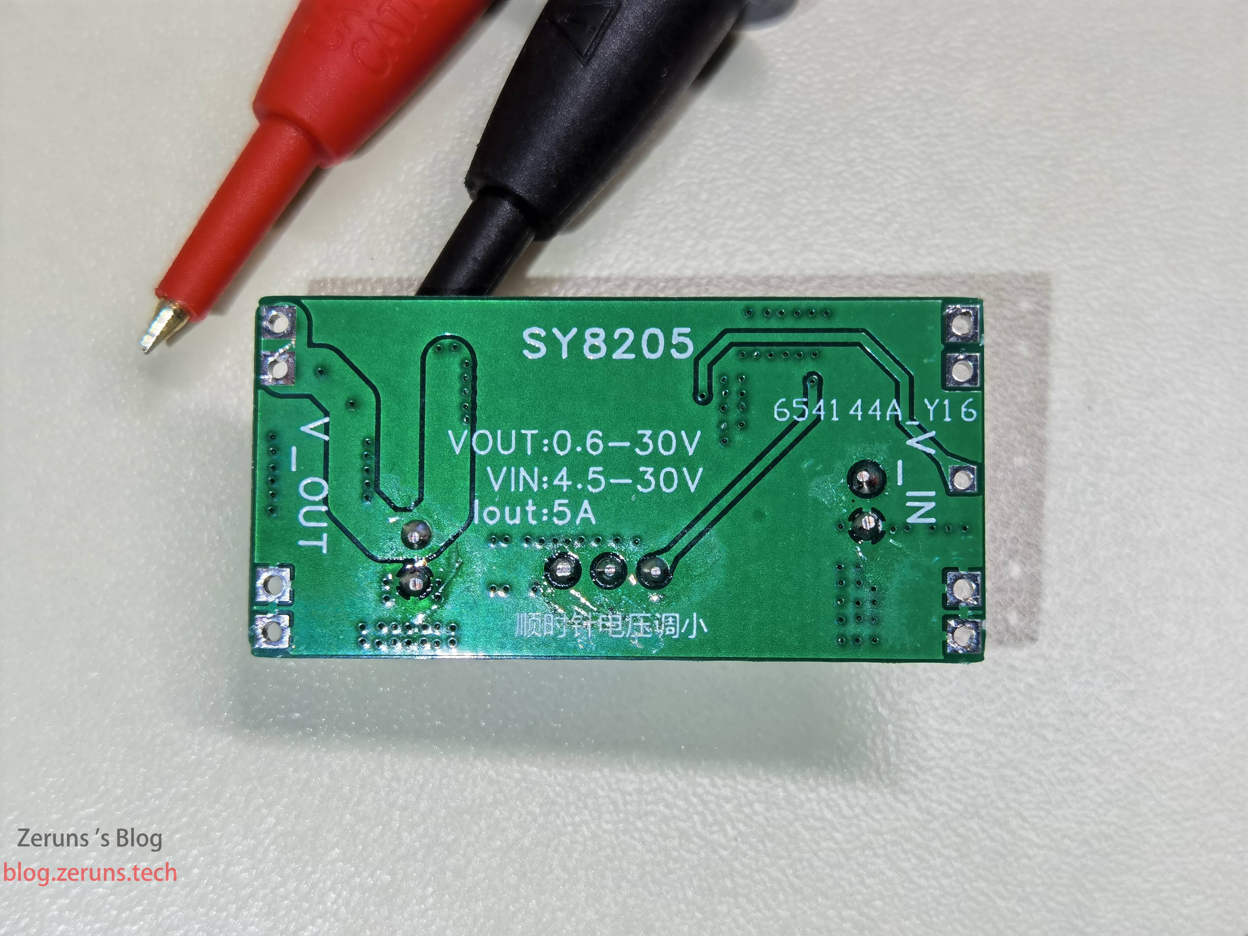
SY8205 Synchronous Buck Step-Down Power Module, Input Voltage 4.5-30V, Output Voltage 0.6-30V Adjustable, Efficiency Above 90%, Maximum Continuous Output Current 5A, Peak Current 6A.
Open Source Link: https://url.zeruns.com/obGu3
SY8025 Datasheet Download: https://url.zeruns.com/0SYO7 Extraction Code: 5l5x
- Designed a MSP430F149 minimum system board and open-sourced it: https://blog.zeruns.com/archives/713.html
- STM32F030C8T6 Minimum System Board and LED Chaser (Schematics and PCB): https://blog.zeruns.com/archives/715.html
Electronics/Microcontroller Technology Exchange Group: 2169025065
Introduction
SY8205 is a synchronous buck step-down chip with built-in switching transistor launched by Silergy. The switching frequency is 500kHz, input voltage 4.5-30V, maximum continuous output current 5A, peak current 6A. The FB pin reference voltage is 0.6V with 1.5% accuracy. It features current foldback output short-circuit protection, thermal shutdown protection, automatic recovery function, output enable pin (high level on, low level off), and soft start.
Actual testing shows that when outputting 4A current, the heat generation is enormous and heat dissipation must be added. Without any heat dissipation, the output current that can run continuously for a long time is around 3A.
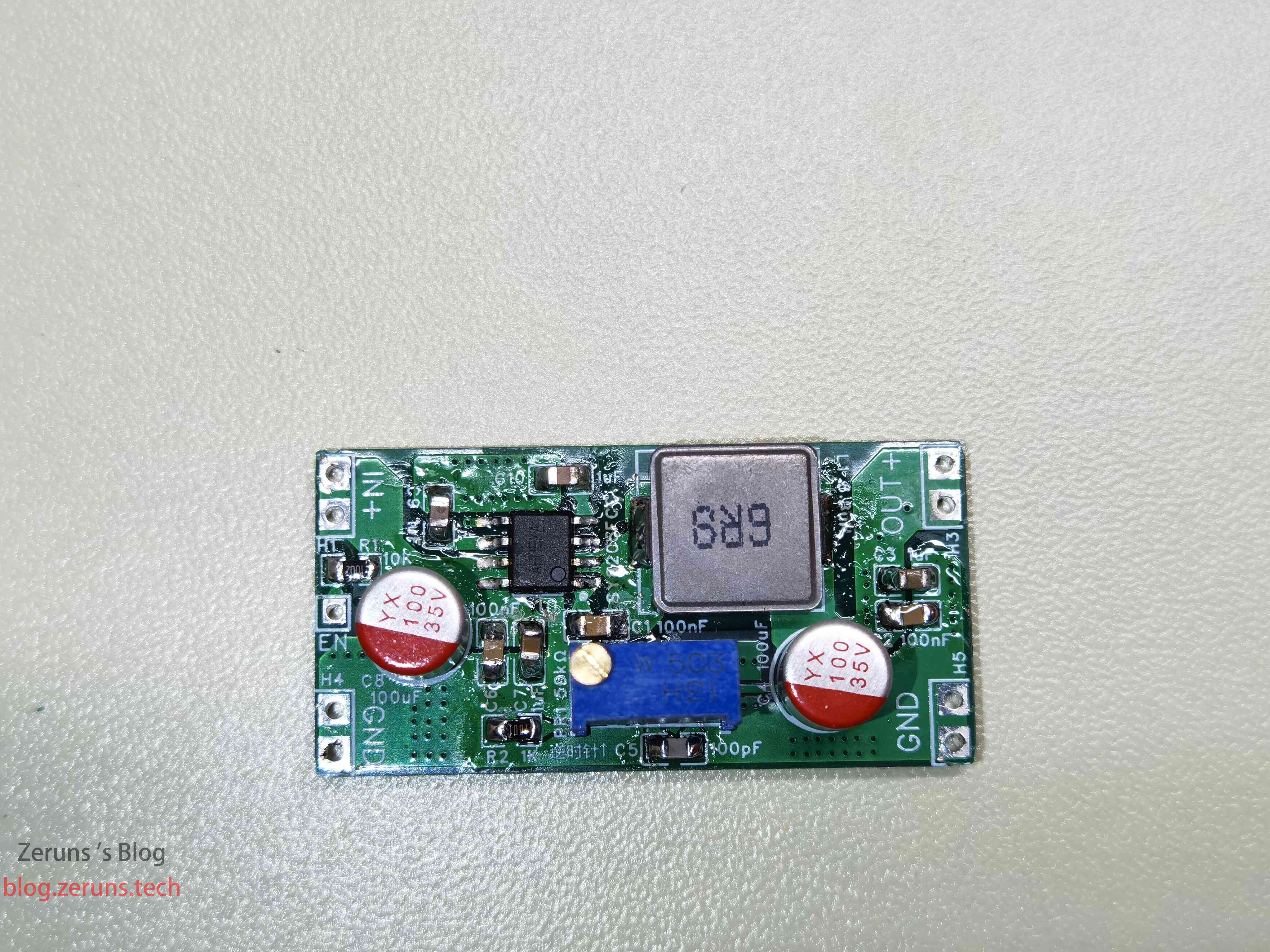
The following test data was obtained after replacing two 100μF solid-state capacitors with 220μF high-frequency electrolytic capacitors. It seems that 100μF capacitors are a bit small.
A student project, please give me some advice.
Efficiency Test
| Input Voltage | Input Current | Input Power | Output Voltage | Output Current | Output Power | Efficiency |
|---|---|---|---|---|---|---|
| 15V | 0.868A | 13.02W | 11.95V | 1A | 11.95W | 91.8% |
| 15V | 2.48A | 37.2W | 11.87V | 2.99A | 35.49W | 95.4% |
| 25V | 2.595A | 64.88w | 12.19V | 4.98A | 60.71W | 93.6% |
| 15V | 0.35A | 5.25W | 5.01V | 1A | 5.01W | 95.4% |
| 15V | 1.46A | 21.9W | 5.02V | 3.98A | 19.98W | 91.2% |
Ripple Test
The method for measuring ripple below is somewhat improper, with too long a ground loop, so the measured ripple may be larger.
At 18V input and 12V output no-load ripple, around 6.8Hz, peak-to-peak value around 500mV.
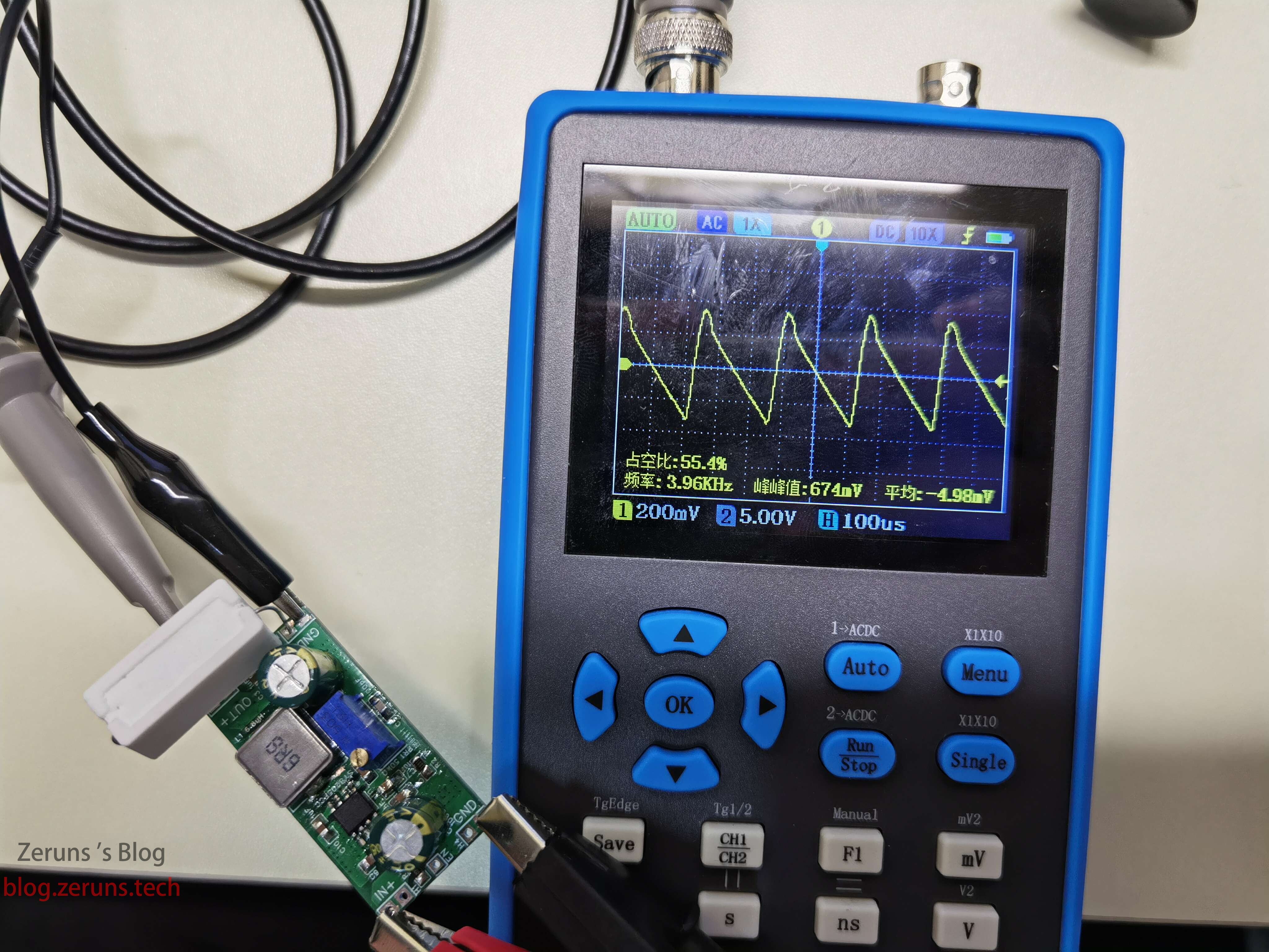
At 18V input, 12V output, with a 20Ω cement resistor as load, ripple around 4kHz, peak-to-peak value around 670mV.
The ripple is somewhat large, it seems the filter capacitor is too small. It is recommended to change the filter capacitor to 470μF, and the PCB needs further adjustment and optimization.

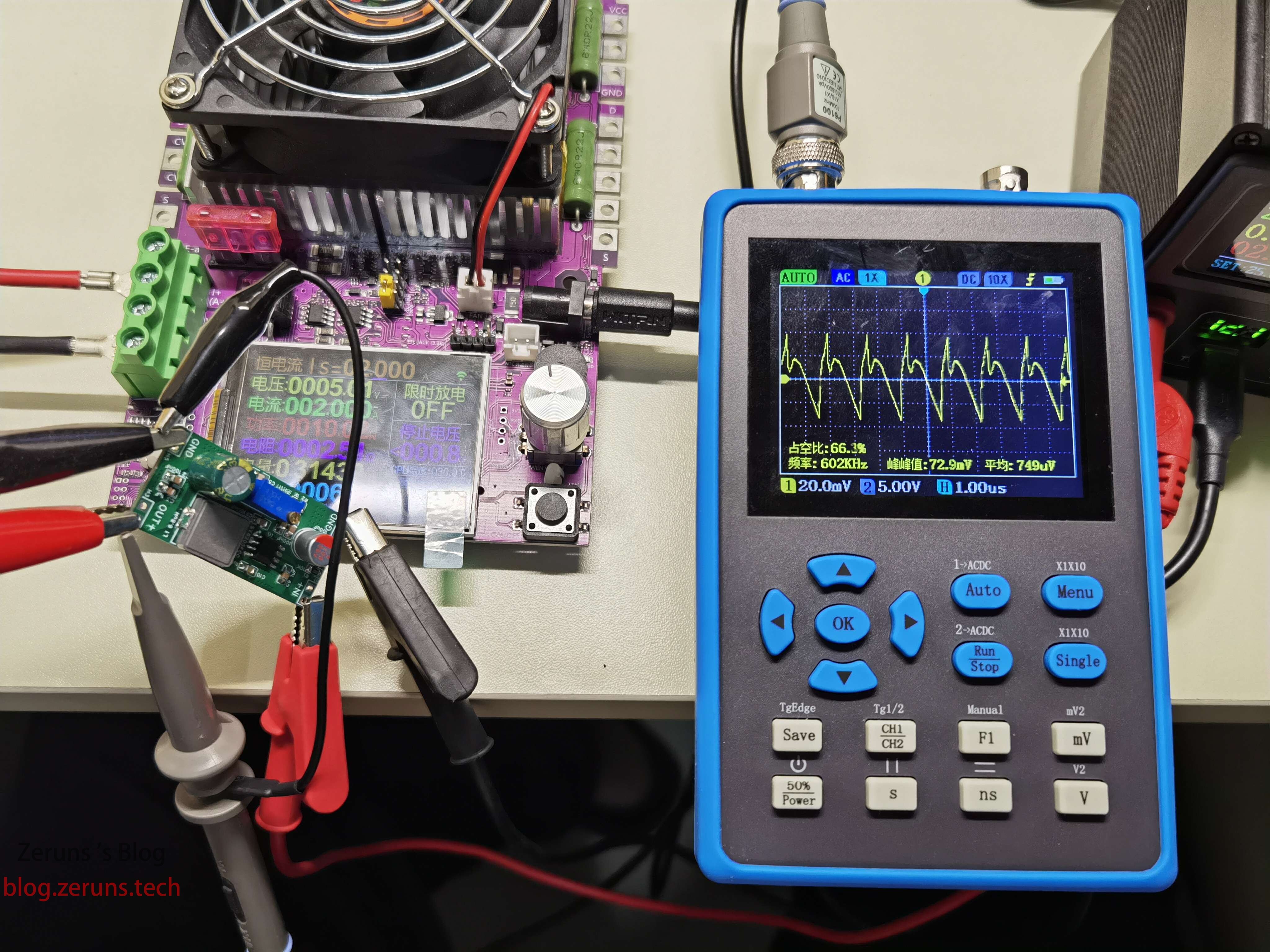
Re-tested the ripple on 2023.6.15, this time with a larger current, and the ripple indeed became much smaller. The above test results were because when the current is small it is in PFM mode. Actual testing shows that when the current is below about 1.4A, it enters PFM mode.
At 25V input, 5V 2A output, the ripple peak-to-peak value is around 72mV.
At 25V input, 12V 3A output, the ripple peak-to-peak value is around 130mV.

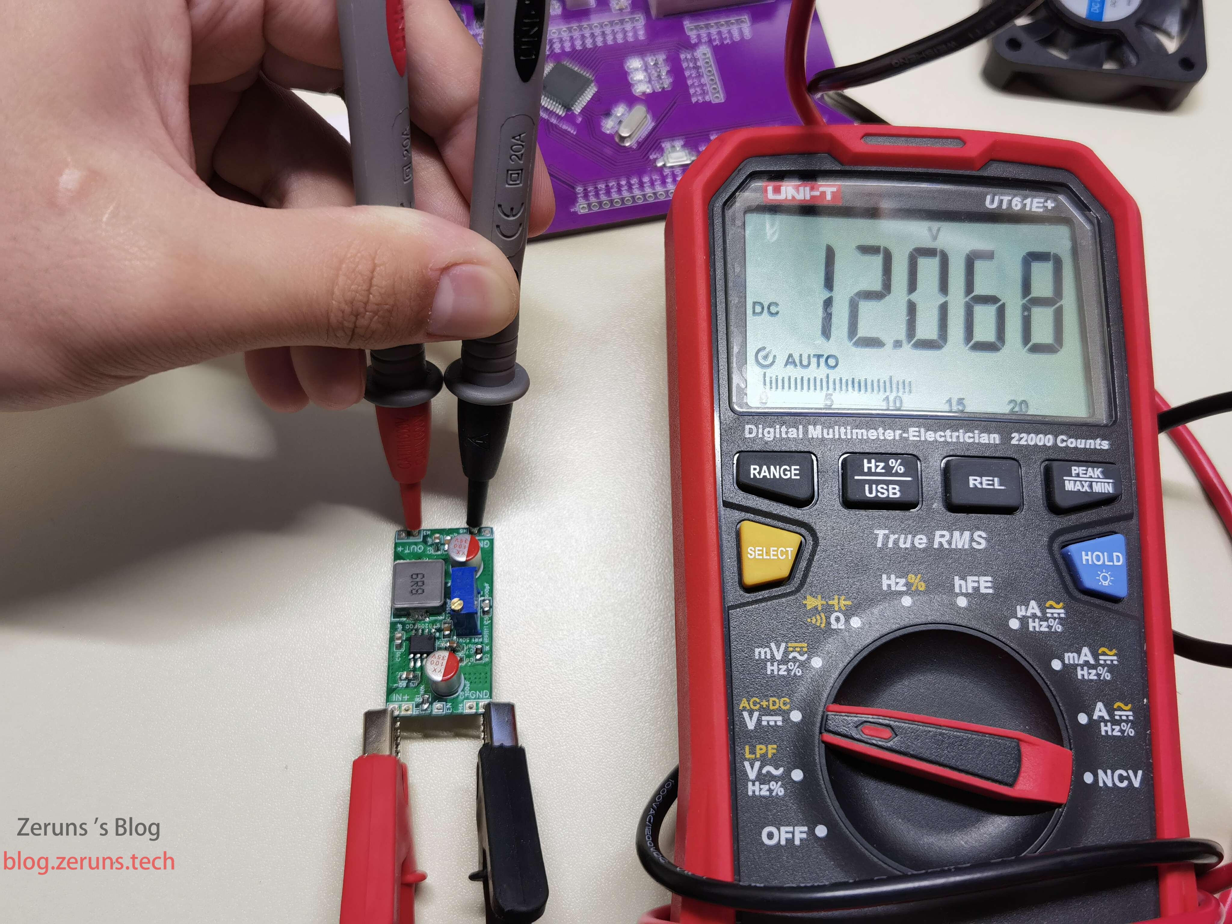
Physical Photos
Component Purchase Links
- 0805 Resistor Sample Pack: https://s.click.taobao.com/oWjIgGu
- 0805 Capacitor Sample Pack: https://s.click.taobao.com/r9ea1Hu
- SY8205 Chip: https://s.click.taobao.com/klaXQGu
- Electrolytic Capacitor: https://s.click.taobao.com/r6CWQGu
- Adjustable Resistor: https://s.click.taobao.com/eTaBmGu
Component purchase recommendation: LCSC Mall, discount registration link: https://activity.szlcsc.com/invite/D03E5B9CEAAE70A4.html
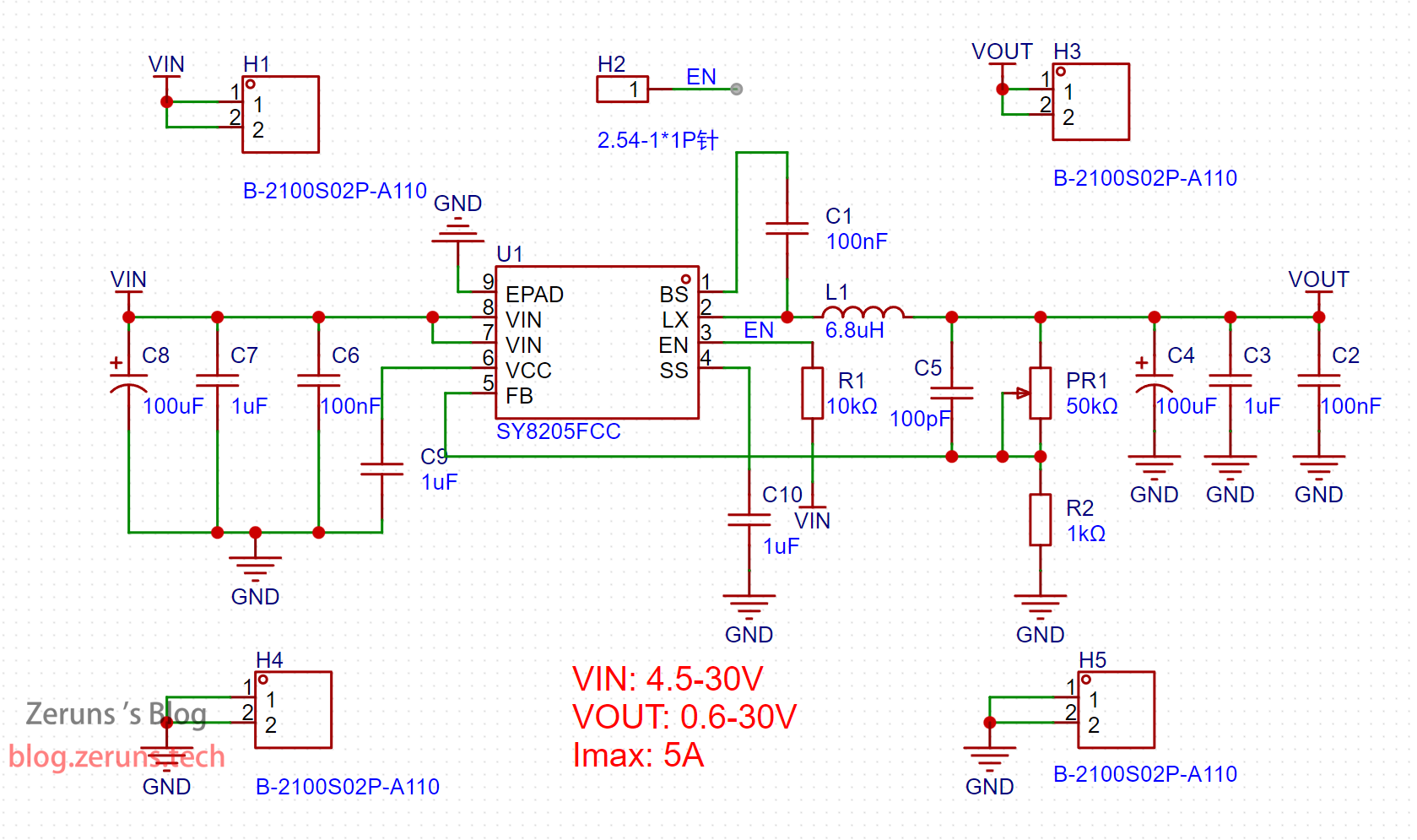
Schematic
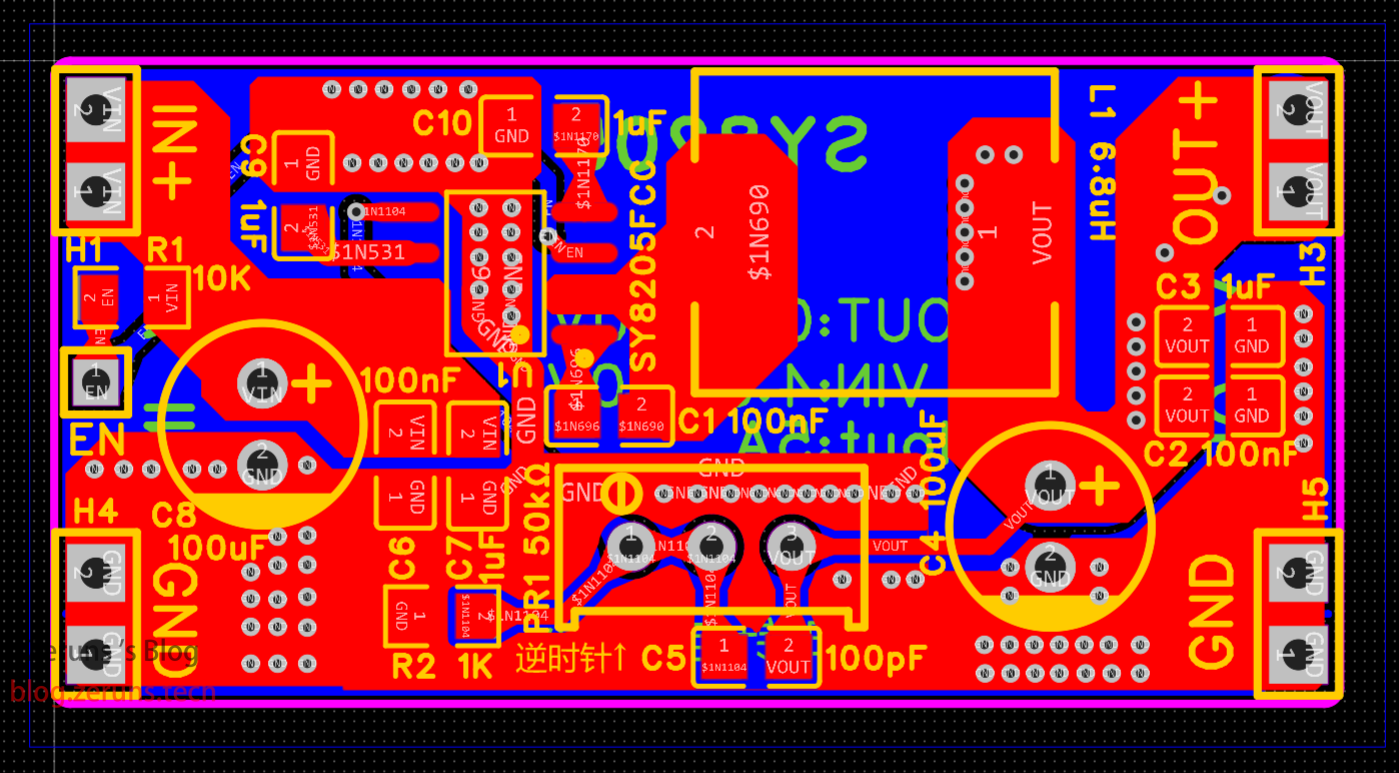
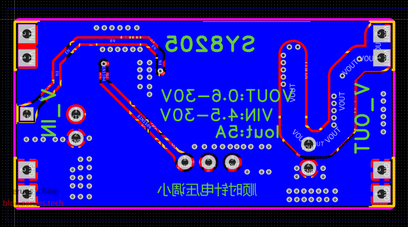
PCB
Recommended Reading
- High Cost-Performance and Cheap VPS/Cloud Server Recommendations: https://blog.vpszj.cn/archives/41.html
- How to Build a Personal Blog: https://blog.zeruns.com/archives/218.html
- Minecraft Server Setup Tutorial: https://blog.zeruns.com/tag/mc/
- STM32 Reading SHT3x Series Temperature and Humidity Sensors: https://blog.zeruns.com/archives/700.html
- Using VSCode to Replace Keil for STM32 and 51 Microcontroller Development: https://blog.zeruns.com/archives/690.html