2011 National Electric Contest Problem – Switching Power Module Parallel Power Supply System. Two XL4015 chips serve as DC-DC modules outputting 8 V; master–slave current-sharing is adopted, enabling accurate current allocation in multiple ratios with efficiency above 80 %.
Electronics / MCU Technology Group: 2169025065
Topic
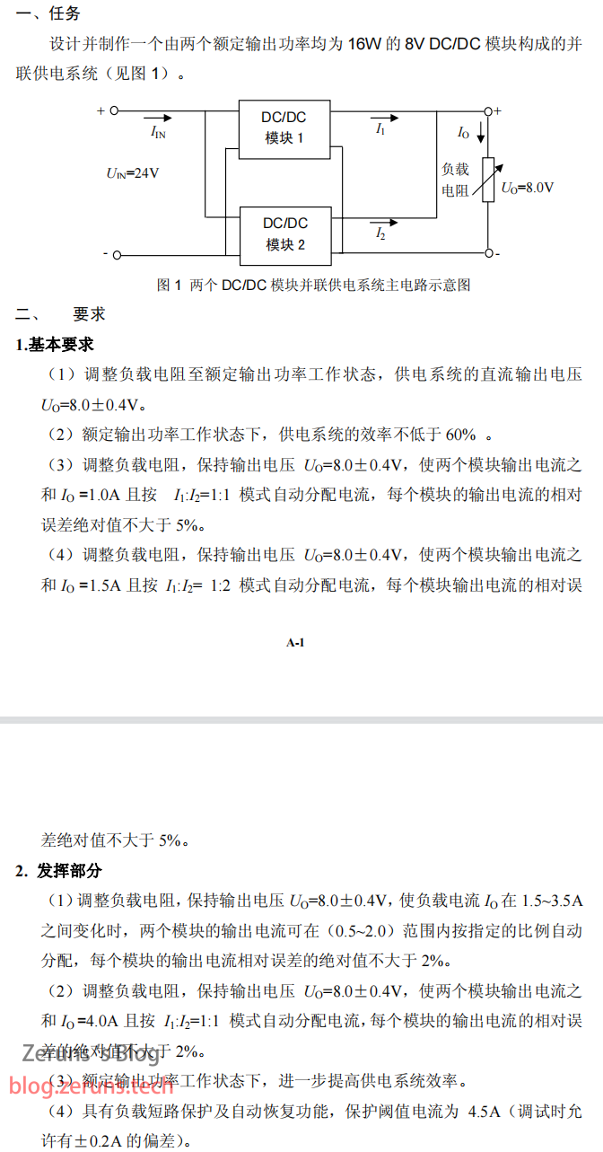
Design and build a parallel power-supply system composed of two 8 V DC-DC modules each rated at 16 W output power.
Introduction
This entry uses the master–slave current-sharing method and consists of a constant-current source (slave), constant-voltage source (master), MCU control board, auxiliary power supply, etc. XL4015 is employed in both modules for buck step-down; Hezhou AIR32F103CCT6 MCU is the control core, and INA199 current-sense amplifier provides 50× gain for current sampling. The two sensed signals are summed in a non-inverting adder; the adder output is divided by fixed resistors and a digital potentiometer, then fed through a voltage follower and LM358 comparator back to the FB pin of the XL4015 in the slave module (constant-current source) to control its current and realise current allocation.
Note: On first use, disconnect the parallel-output jumper cap, adjust the constant-voltage source (master) to 8 V, and set the constant-current source (slave) 0.3–0.5 V higher than the master.
Campus contest selection work—comments from experts are welcome.
LCSC open-source link: https://url.zeruns.com/GrMC6
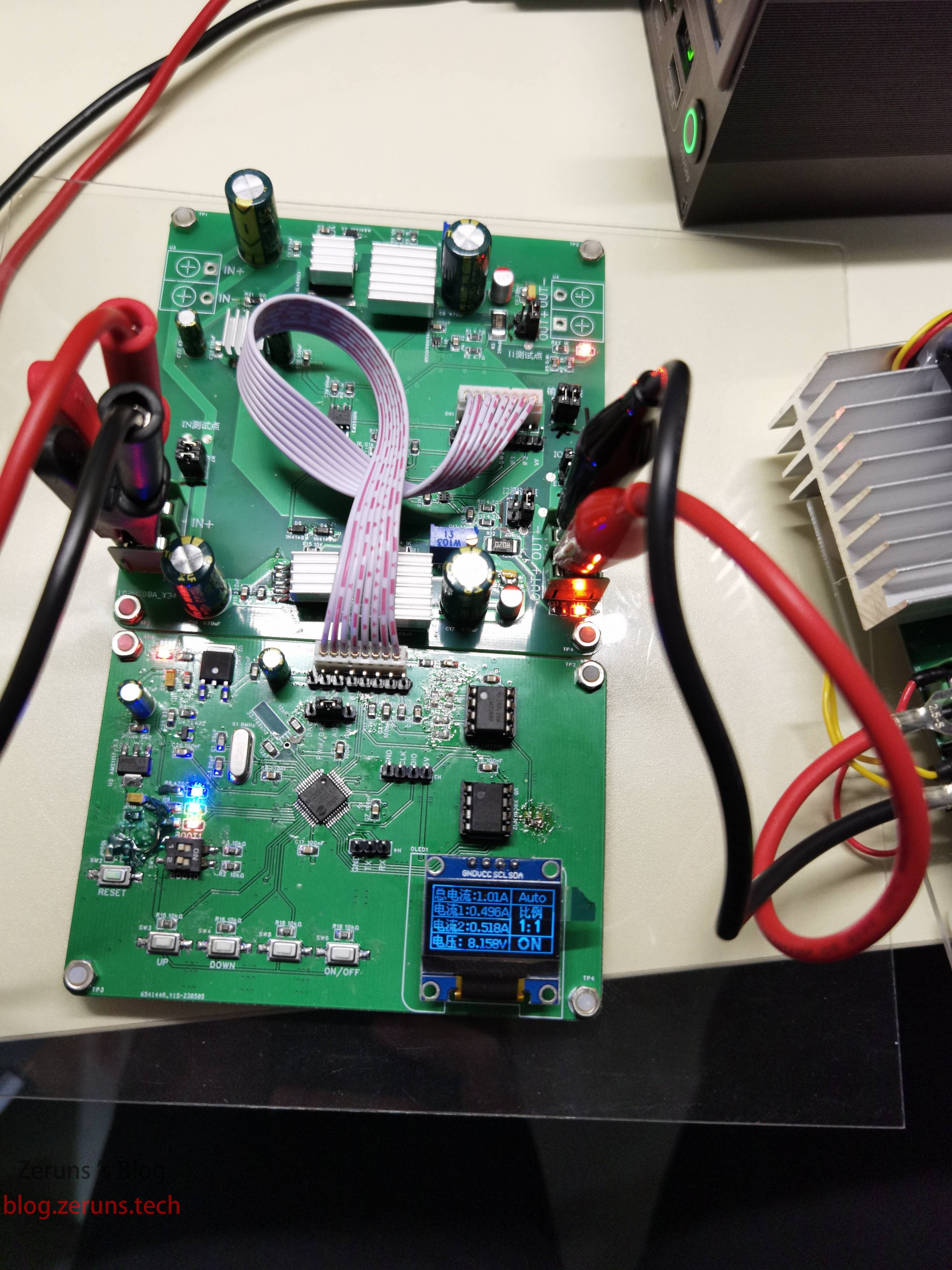
Photos

Downloads
Source code: https://url.zeruns.com/nSNjc Extraction code: swoz
Datasheets: https://url.zeruns.com/TBn42 Extraction code: j542
Test Data
- DC output voltage & efficiency test
Method: adjust load resistor until I₀≈4 A, record U₀, UIN, I₀, IIN.
| Uin(V) | Iin(A) | U0(V) | I0(A) | Efficiency |
|---|---|---|---|---|
| 24.05 | 1.57 | 7.76 | 3.97 | 81.6 % |
Conclusion: output 7.76 V, system efficiency 81.6 %.
- Relative current error at I₀=1 A & 1.5 A
Method: adjust load to 1 A or 1.5 A, record U₀, UIN, I₁, I₂, I₀, IIN.
I₀=1 A:
| Uin(V) | Iin(A) | U0(V) | I1(A) | I2(A) | I0(A) | Error1 | Error2 |
|---|---|---|---|---|---|---|---|
| 24.08 | 0.454 | 7.999 | 0.501 | 0.526 | 1.032 | 2.9 % | 1.9 % |
I₀=1.5 A:
| UIN(V) | IIN(A) | U0(V) | I1(A) | I2(A) | I0(A) | Error1 | Error2 |
|---|---|---|---|---|---|---|---|
| 24.06 | 0.635 | 7.969 | 0.498 | 1.052 | 1.523 | 1.9 % | 3.6 % |
Conclusion: relative error ≤3.6 %, better than the required <5 %.
- Relative error for 1.5 A < I₀ < 3.5 A with set ratios
Method: fix 1.5 A total, test ratios 1:1, 1:2, 2:1, 2:3, 3:2.
| Ratio | UIN(V) | IIN(A) | U0(V) | I1(A) | I2(A) | I0(A) | Error1 | Error2 |
|---|---|---|---|---|---|---|---|---|
| 1:1 | 24.06 | 0.628 | 7.952 | 0.778 | 0.744 | 1.522 | 2 % | 2 % |
| 1:2 | 24.06 | 0.63 | 7.972 | 0.500 | 1.025 | 1.522 | 1.4 % | 1.1 % |
| 2:1 | 24.05 | 0.627 | 7.931 | 1.015 | 0.509 | 1.524 | 0.01 % | 0.2 % |
| 2:3 | 24.07 | 0.629 | 7.963 | 0.604 | 0.920 | 1.522 | 0.7 % | 0.7 % |
| 3:2 | 24.06 | 0.626 | 7.923 | 0.926 | 0.595 | 1.524 | 1.25 % | 2 % |
Conclusion: relative error ≤2 %, meets specification.
- Relative error at I₀=4 A
Method: adjust load to ≈4 A.
| UIN(V) | IIN(A) | U0(V) | I1(A) | I2(A) | I0(A) | Error1 | Error2 |
|---|---|---|---|---|---|---|---|
| 24.04 | 1.568 | 7.73 | 1.96 | 1.945 | 3.968 | 1.2 % | 1.9 % |
Conclusion: relative error ≤2 %, meets specification.
Component Purchase Links
- 0805 resistor sample book: https://s.click.taobao.com/oWjIgGu
- 0805 capacitor sample book: [https://s.click.taobao.com/r9ea1Hu](https://s.click.taobao.com/t?e=m%3D2%26s%3DHUOwk6IKUTtw4vFB6t2Z2ueEDrYVVa64K7Vc7tFgwiHjf2vlNIV67nYY5qxgQ5pjPkWZNjOK2CN%2FmzaS0s2vXCsmIF0UHtujBkxkgN7jKg%2BiJaQjFxYBevWfPAv4x3d%2FOlGkMkr%2BSUUYmUGuVZn0uUeNaL1L6rWLYVnYE523ghoLZMqoQW%2BfuKGzo1lVxIioZ7PkP5ESYSK2NOnbQ%2FlO5lq7XGYat254ig%