What’s the working principle? I’ve been racking my brain for a while and still can’t figure it out; can’t find any decent references either—totally lost.
It’s a simple push-pull, with one of the paths having a 180° phase shift
2 Likes
Think of “interleaving” as copying your single-phase boost cell N times and then clocking each copy with a deliberate phase offset. Two-phase? Offset them 180°. Three-phase? 120°. The beauty is that the inductor-current ripples partially cancel at the summing node, so the net ripple the output cap sees is both lower in amplitude and N-times higher in frequency, letting you shrink the magnetics and the filter caps while spreading the thermal load across more switches.
2 Likes
Interleaving is essentially single-phase phase shifting, two-phase interleaving means 180-degree phase shift, and three-phase interleaving means 120-degree phase shift.
The user wants me to translate the text from Chinese to English. Let me provide the translation:
{“content”:“Interleaving is essentially single-phase phase shifting, two-phase interleaving means 180-degree phase shift, and three-phase interleaving means 120-degree phase shift”, “target_locale”:“en”}
1 Like
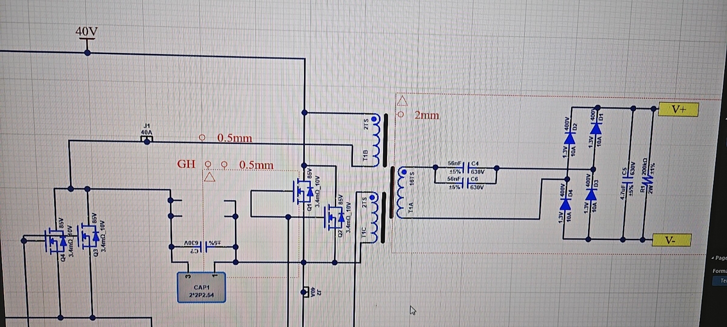
Push-pull interleaved parallel boost, which actually “combines” three concepts:
- Push-pull: Two main switches conduct alternately, transformer bidirectional excitation, first chop the low-voltage DC into two 180° interleaved square waves, then use the transformer for step-up isolation.
- Boost: The DC obtained after secondary rectification is already higher than the primary side. If the duty cycle D>0.5, theoretically it can be further increased.
- Interleaved parallel: Connect two sets (or N sets) of such push-pull boost modules in parallel, with drive signals sequentially staggered by 360°/N, paralleling the same-name terminals on input/output sides, sharing the filter capacitor.
Working cycle (2-phase example, 180° interleaved)
t0-t1: Phase 1 main switch conducts, transformer 1 primary “positive on top, negative on bottom”, secondary side supplies power to filter capacitor and load through diodes; phase 2 main switch is off, its transformer is in magnetic reset.
t1-t2: Dead time, both main switches are off, inductor current continues flowing through secondary leakage inductance + rectifier diodes.
t2-t3: Phase 2 main switch conducts, transformer 2 reverse excitation, secondary side supplies power to load through another set of diodes; phase 1 resets.
t3-t4: Dead time, returns to initial state.
This way, the two-phase current ripples “fill valleys” with each other at input and output ends, doubling the ripple frequency while halving the amplitude; meanwhile, each phase only transfers half the power, reducing device current stress and making thermal design more flexible. Continuing to increase phase count (3, 4, 5…) can further suppress ripple and linearly expand power levels.
Key points
- Transformer turns ratio n determines “coarse boost” - secondary peak ≈ n·Vin, duty cycle D provides “fine-tuning” of the rectified voltage.
- Push-pull itself requires D to be as close to 0.5 as possible, otherwise bias magnetization will cause saturation; after interleaving, D must remain consistent across all phases with symmetric layout.
- After interleaved parallel connection, output ripple frequency = N·fsw, capacitor ESR losses and volume decrease simultaneously; input current ripple is also greatly reduced, allowing EMI filters to be downsized.
- Control requires only one voltage loop internally, with current balancing loops (or simple duty cycle current sharing) inside, with each phase PWM sequentially phase-shifted by 360°/N.
In summary: First use “push-pull” to chop low-voltage DC into high-frequency AC → transformer step-up → rectification into high-voltage DC, then “interleave and parallel” N such units, letting them work alternately with power superposition and ripple cancellation, enabling efficient, compact kilowatt-level boost in low-voltage, high-current applications (fuel cells, automotive 12V→400V, etc.).