OWON(利利普) HDS160 四位半 示波万用表 简单开箱测评和拆解。
前言
最近买了个四位半的万用表,OWON的HDS160,选它主要是因为他的示波器功能,且可以直接用万用表表笔测,无需更换探头,可以直接测量电压或电流波形,虽然只有1MHz带宽,但够用了,更高频率的信号就换示波器,主要是测电流波形方便,而且还可以自动识别表笔插入的孔位自动切换电压/电流档,很方便。
我是365元买入的。
![]() HDS160/HDS120购买地址:
HDS160/HDS120购买地址:
- 淘宝第三方店:https://s.click.taobao.com/7ZVqsen
- 淘宝OWON旗舰店:https://s.click.taobao.com/ovsosen
- 京东:https://u.jd.com/lDdfYPj
![]() 电子/单片机技术交流QQ群: 2169025065
电子/单片机技术交流QQ群: 2169025065
![]() eeClub-电子工程师社区: https://bbs.eeclub.top/
eeClub-电子工程师社区: https://bbs.eeclub.top/
参数
一、万用表部分参数
| 测量类型 | 测量范围 | 最高精度 |
|---|---|---|
| 直流电压 (V) | 60.000mV / 600.00mV / 6.0000V / 60.000V600.00V / 1000.0V | ±(0.05%+5 dig) |
| 交流电压 (V) | 600.00mV / 6.0000V / 60.000V / 600.00V / 750.00V | ±(0.1%+30dig) |
| 直流电流 (A) | 600.00μA / 6000.0μA / 60.000mA / 600.00mA / 6.0000A / 10.000A | ±(0.15%+10dig) |
| 交流电流 (A) | 600.00μA / 6000.0μA / 60.000mA / 600.00mA / 6.0000A / 10.000A | ±(0.5%+20dig) |
| 电阻 (Ω) | 600.00Ω / 6.0000kΩ / 60.000kΩ / 600.00KΩ / 6.0000MΩ / 60.000MΩ | ±(0.15%+10dig) |
| 电容 (F) | 6.000nF / 60.00nF / 600.0nF / 6.000μF / 60.00μF / 600.0μF / 6.000mF / 60.00mF | ±(2.0%+20dig) |
| 频率 (Hz) | 60.00Hz / 600.00Hz / 6.0000kHz / 60.000kHz / 600.00kHz / 6.0000MHz / 60.000MHz | ±(0.2%+10dig) |
| 占空比 | 0.1%~99.9%(典型值:Vrms=1V,f=1kHz) | ±(1.2%+3dig) |
| 占空比 | 0.1%~99.9%(≥1kHz) | ±(2.5%+3dig) |
| 二极管 | 3.0000V | ±(1.0%+10dig) |
| 通断 | 1000.0Ω | - |
| 最大读数 | 60000 | - |
二、示波器功能参数
| 参数项 | 规格 | 参数项 | 规格 |
|---|---|---|---|
| 模拟带宽 | 1MHz(限 ACV 档) | 最大采样率 | 5.0MSa/s |
| 通道数 | 1 | 输入阻抗 | ≈10MΩ |
| 时基范围 | 2.5μS~10S/ div | 时基准确度 | ±(0.01% + 0.1div) |
| 电压垂直灵敏度范围 | 30mV~500V / 网格 | 电流垂直灵敏度范围 | 100μA~5 A / 网格 |
| 垂直波幅准确度 | ±(5% + 0.2div) | 测量功能 | Vmax, Vmin, Vp-p, VavgVrms, Hz |
| 电压最大极限 | 1000V DC+AC 峰值 | 电流最大极限 | 15A DC+AC 峰值 |
| 触发模式 | Auto / Normal / Single | 触发边沿 | 上升沿 / 下降沿 |
| 自动设置 | 时基 / 垂直幅度 / 触发值 | - | - |
三、其他功能和特性
| 功能 / 特性 | 规格 | 功能 / 特性 | 规格 |
|---|---|---|---|
| 电池低电压显示 | √ | 自动关机 | √ |
| 相对测量 | √ | 背光 | √ |
| 输入保护 | √ | 输入阻抗 | ≥10MΩ |
| 安全规范 | CATⅢ 1000V | 显示 | 2.8 英寸 IPS LCD |
| 重量(不带电池) | 0.35kg | 电池 | 单节 18650 锂电池 3.7V |
| 尺寸(长 × 宽 × 高) | 188mm × 93mm × 41.5mm | - | - |
开箱
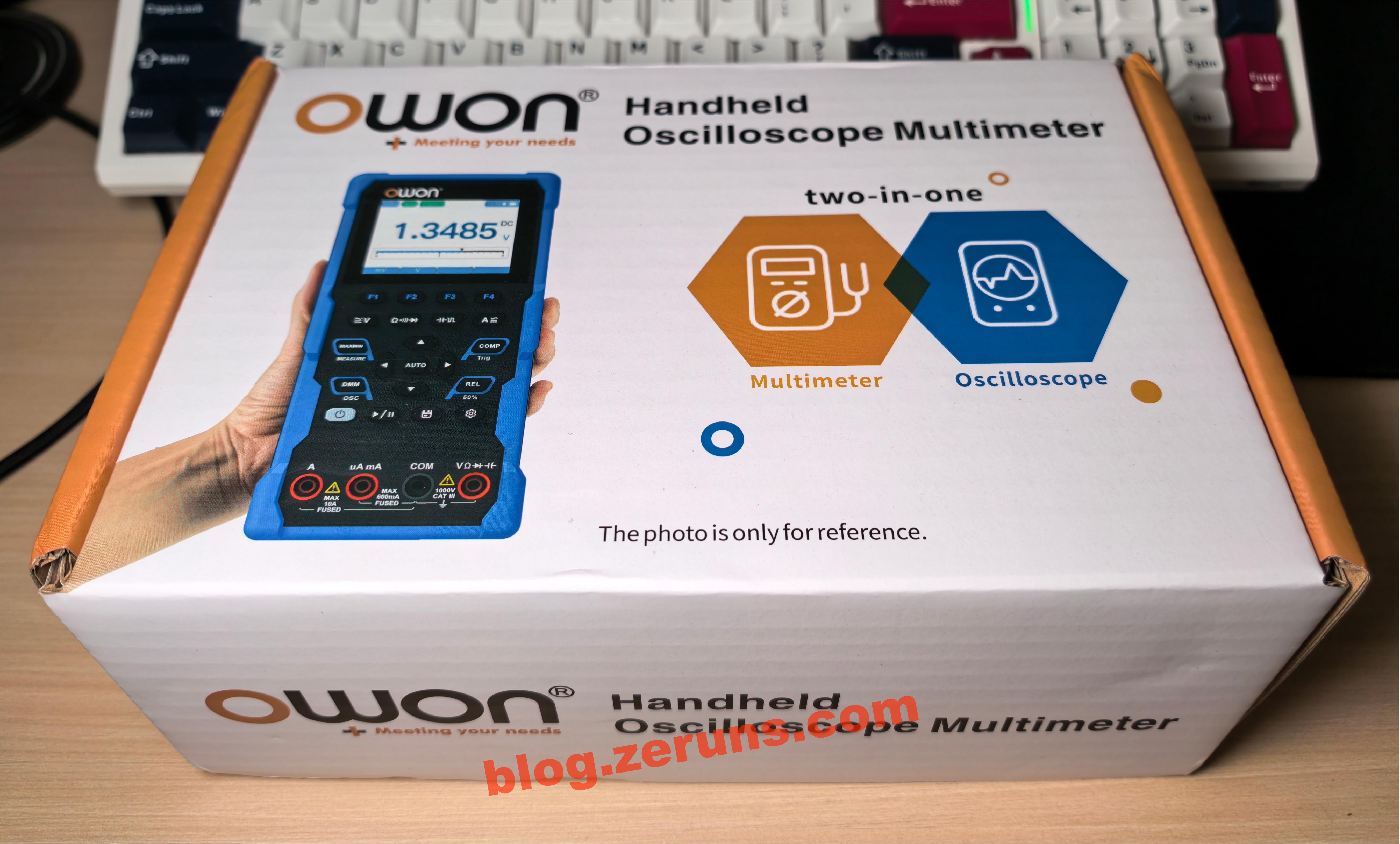
外包装正面,印有 OWON Handheld Oscilloscope Multimeter 字样。
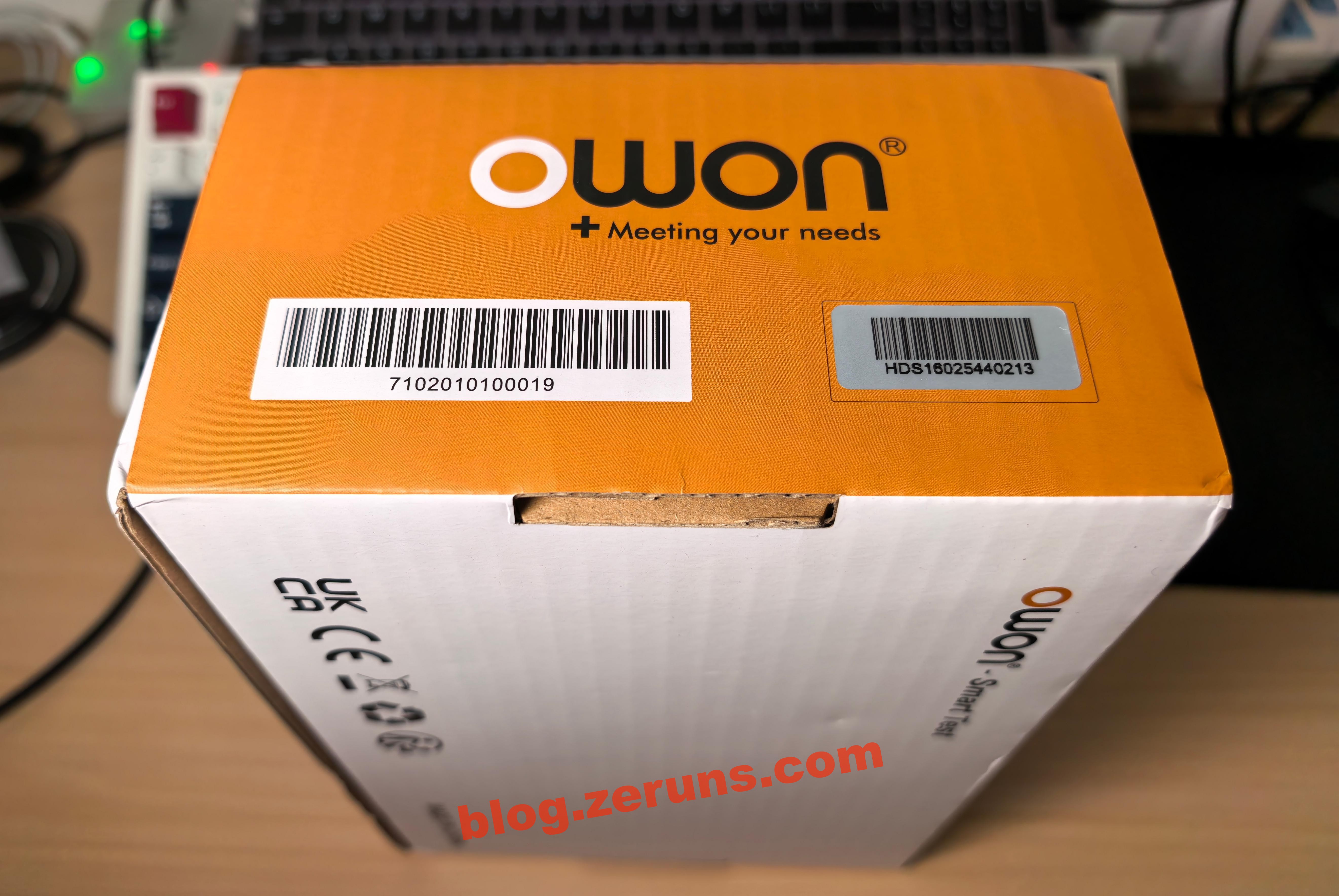
外包装侧面,印有商品条码以及贴了序列号标签。
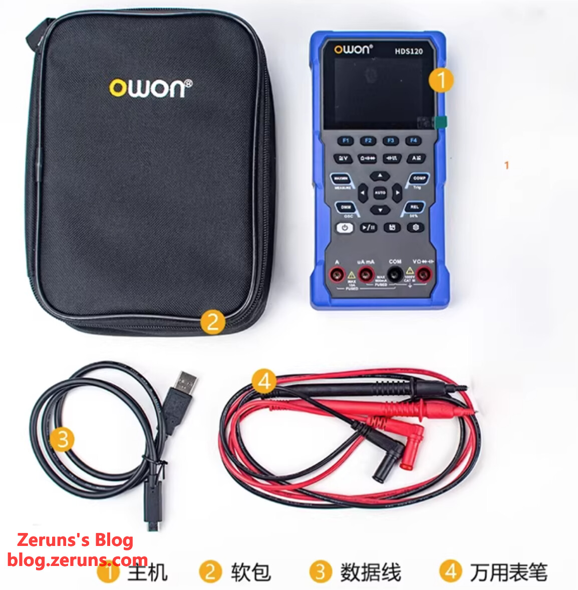
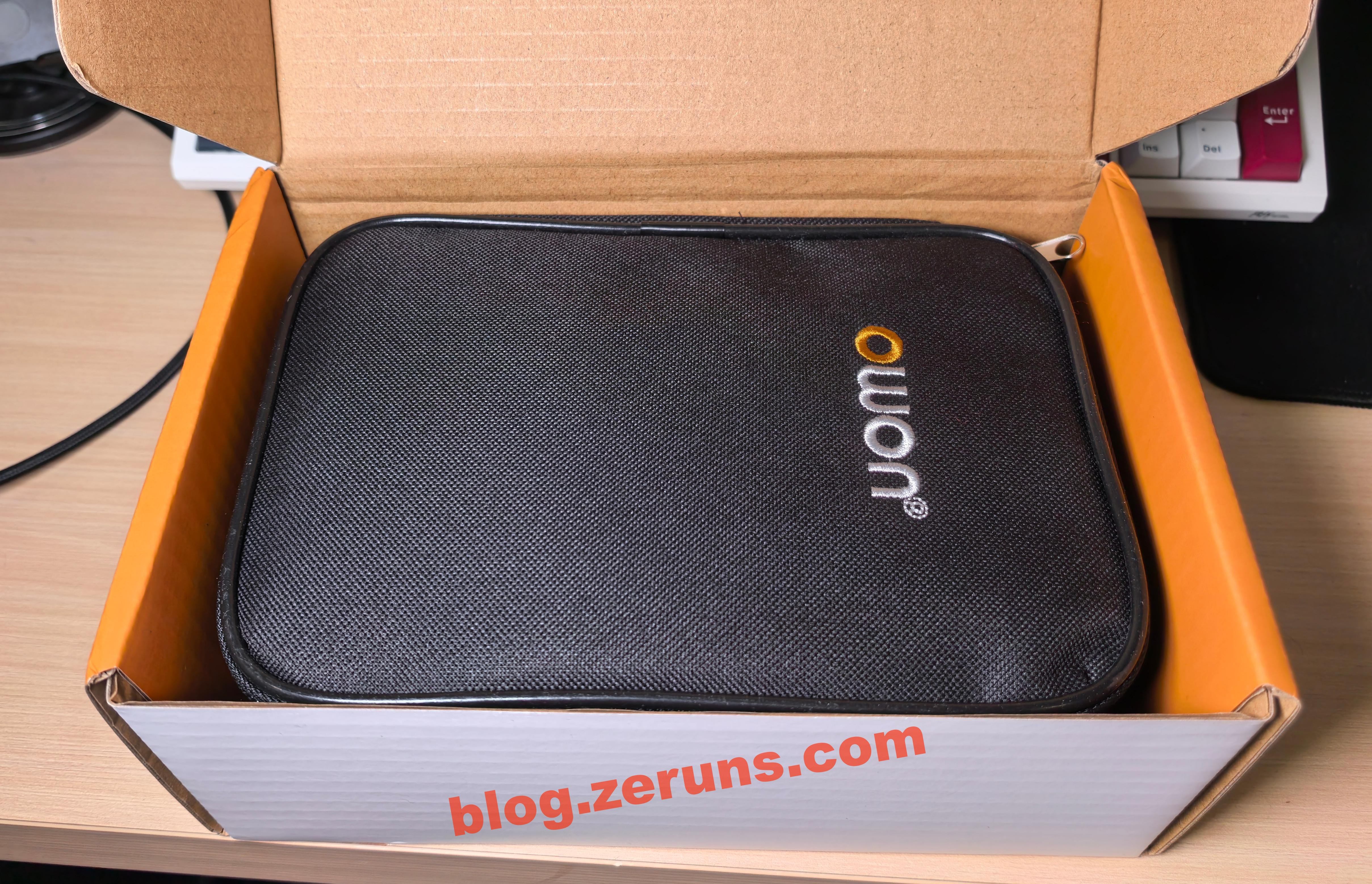
开箱,首先看到的是一个收纳包,东西都放在收纳包里了。
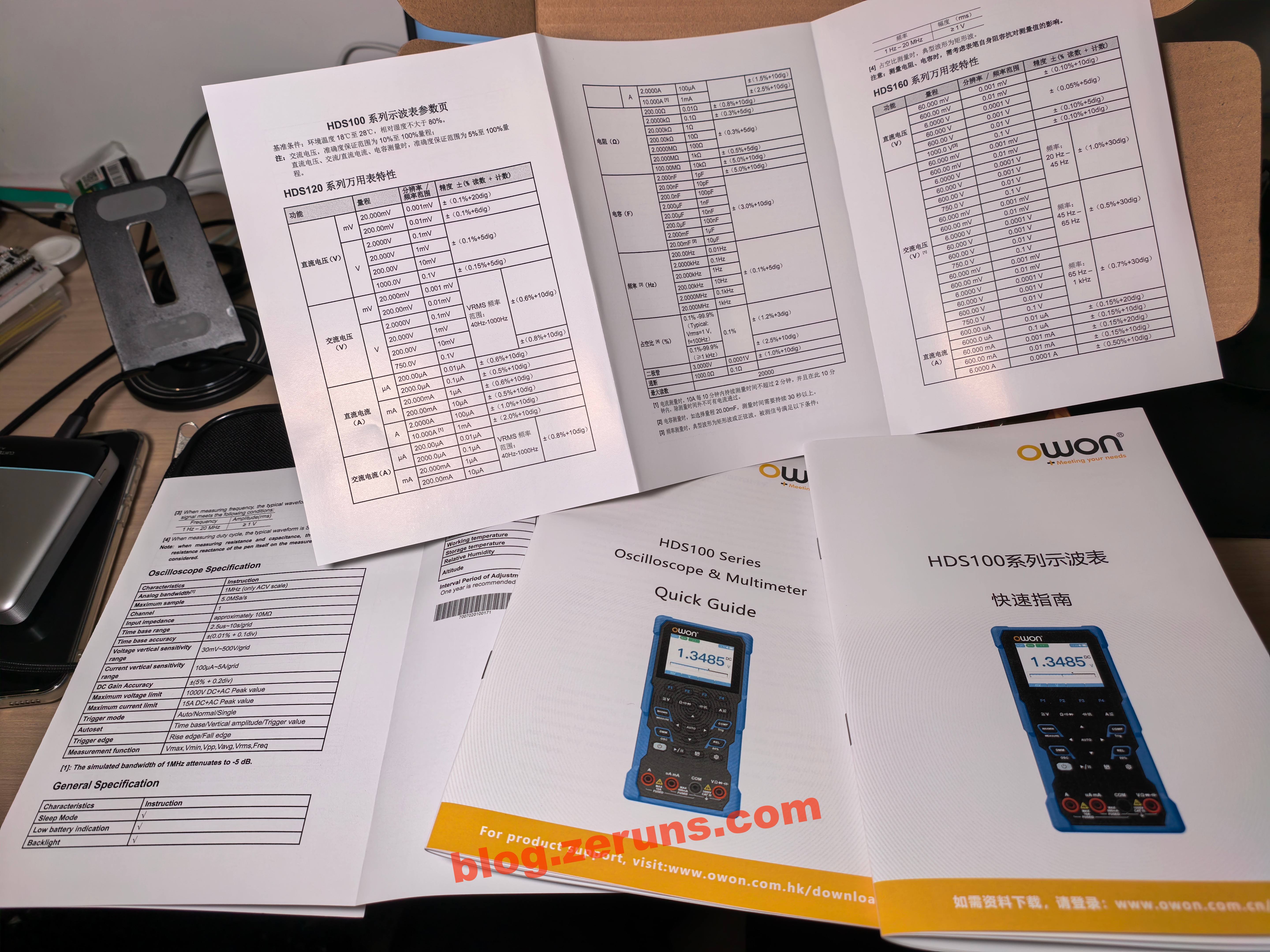
收纳包底下还有说明书。
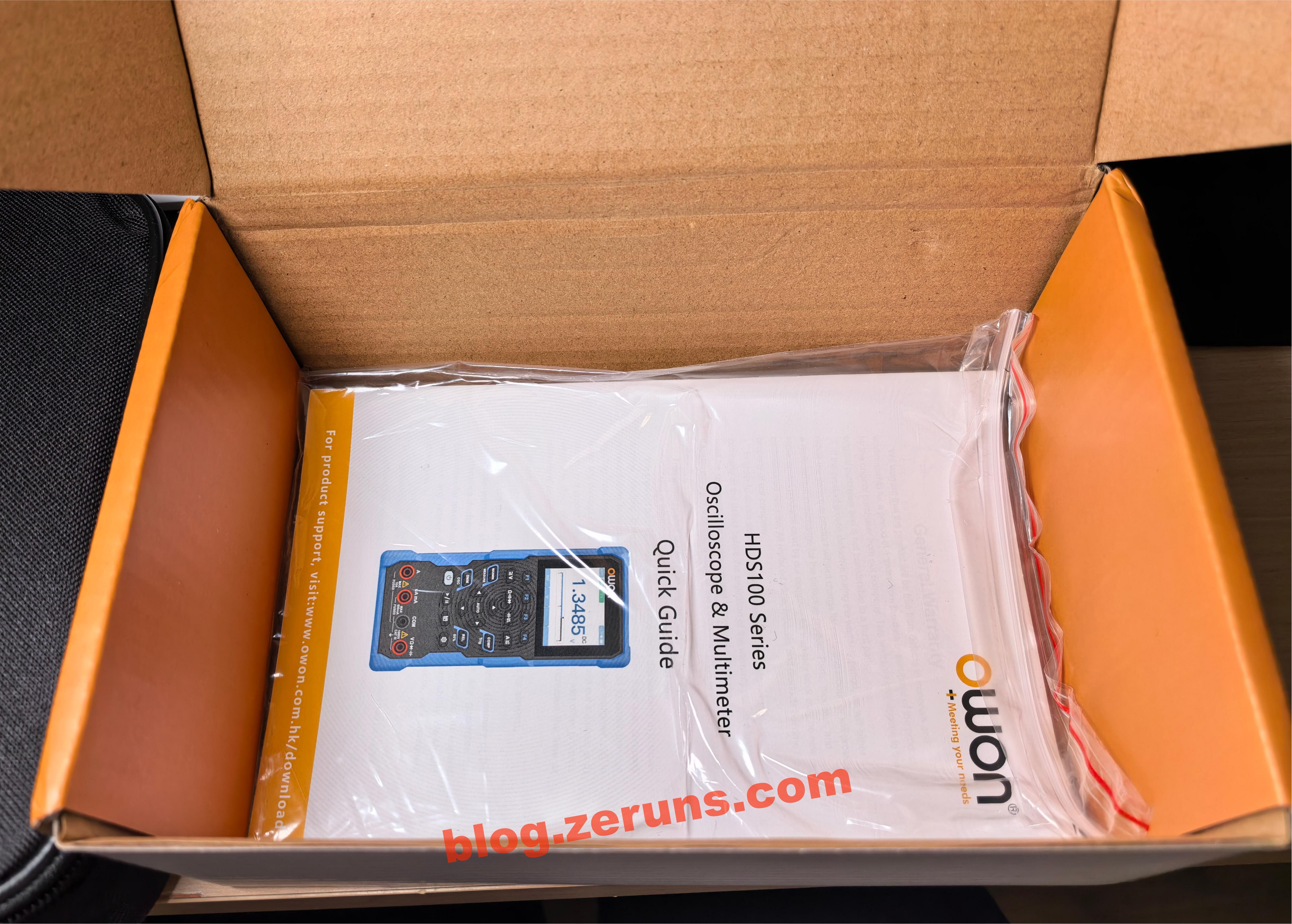
有参数表和快速指南,中英文各一份。
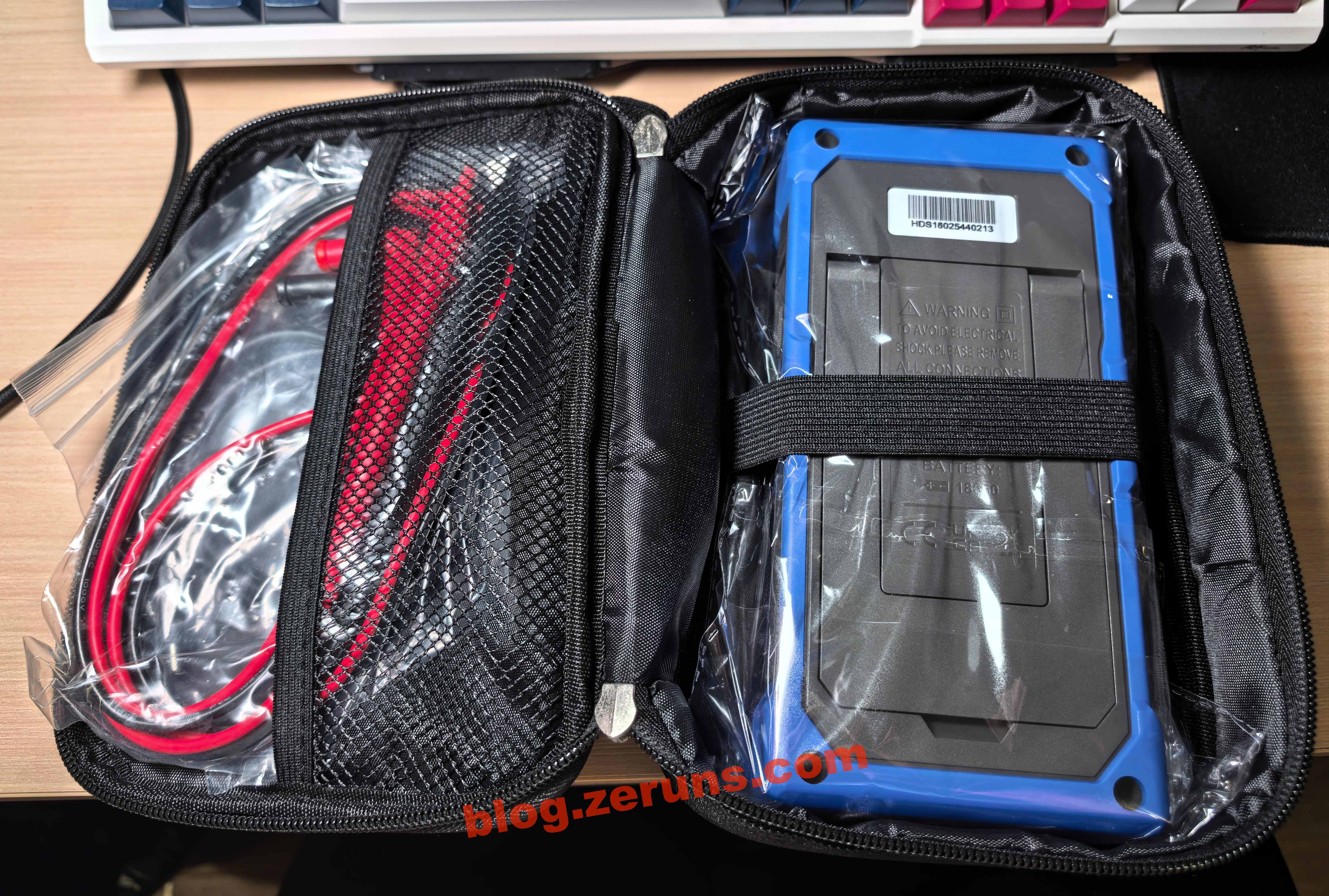
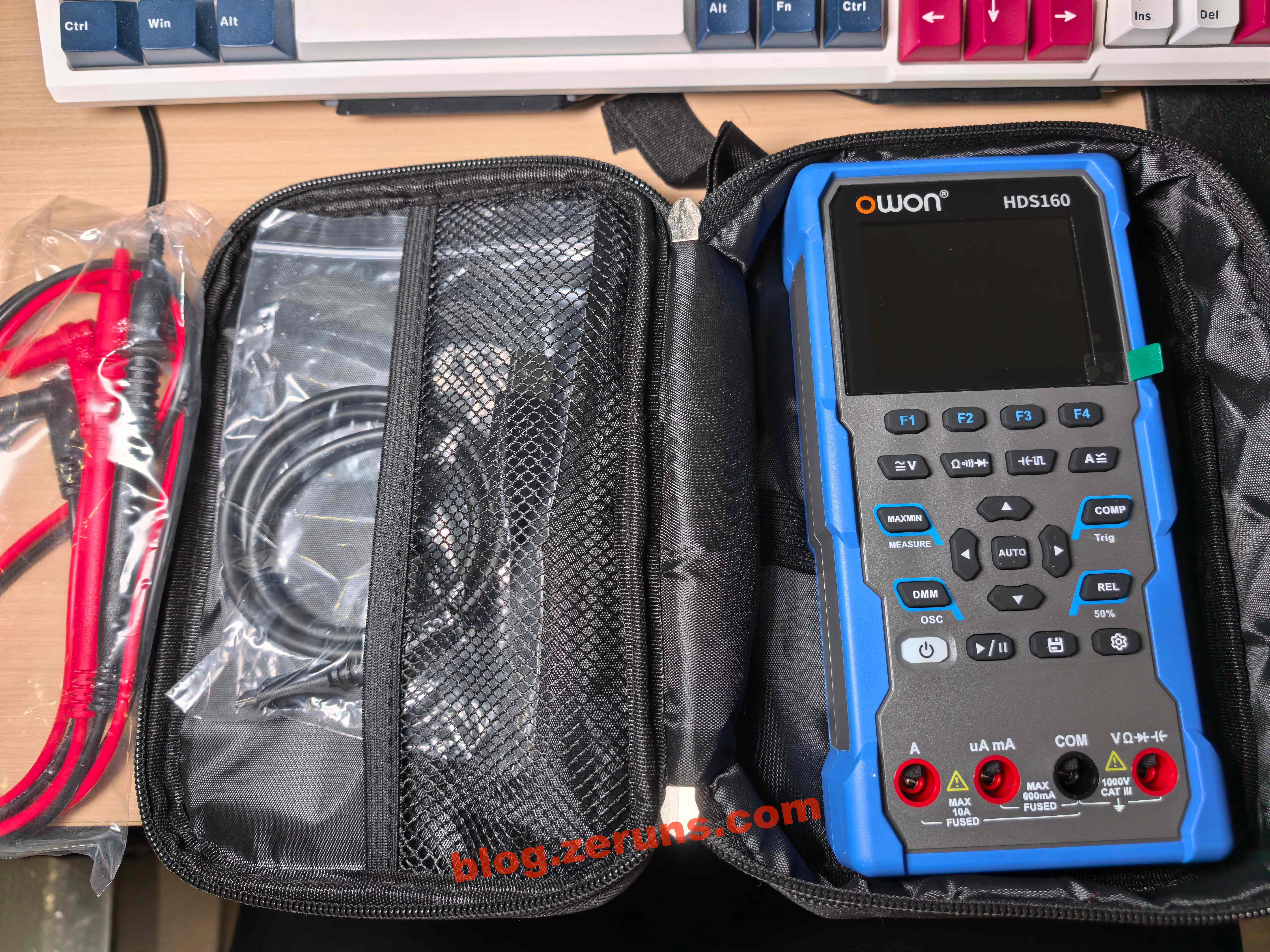
打开收纳包,里面用万用表和表笔(普通表笔,非特尖表笔),以及一条C口数据线。
万用表正面。
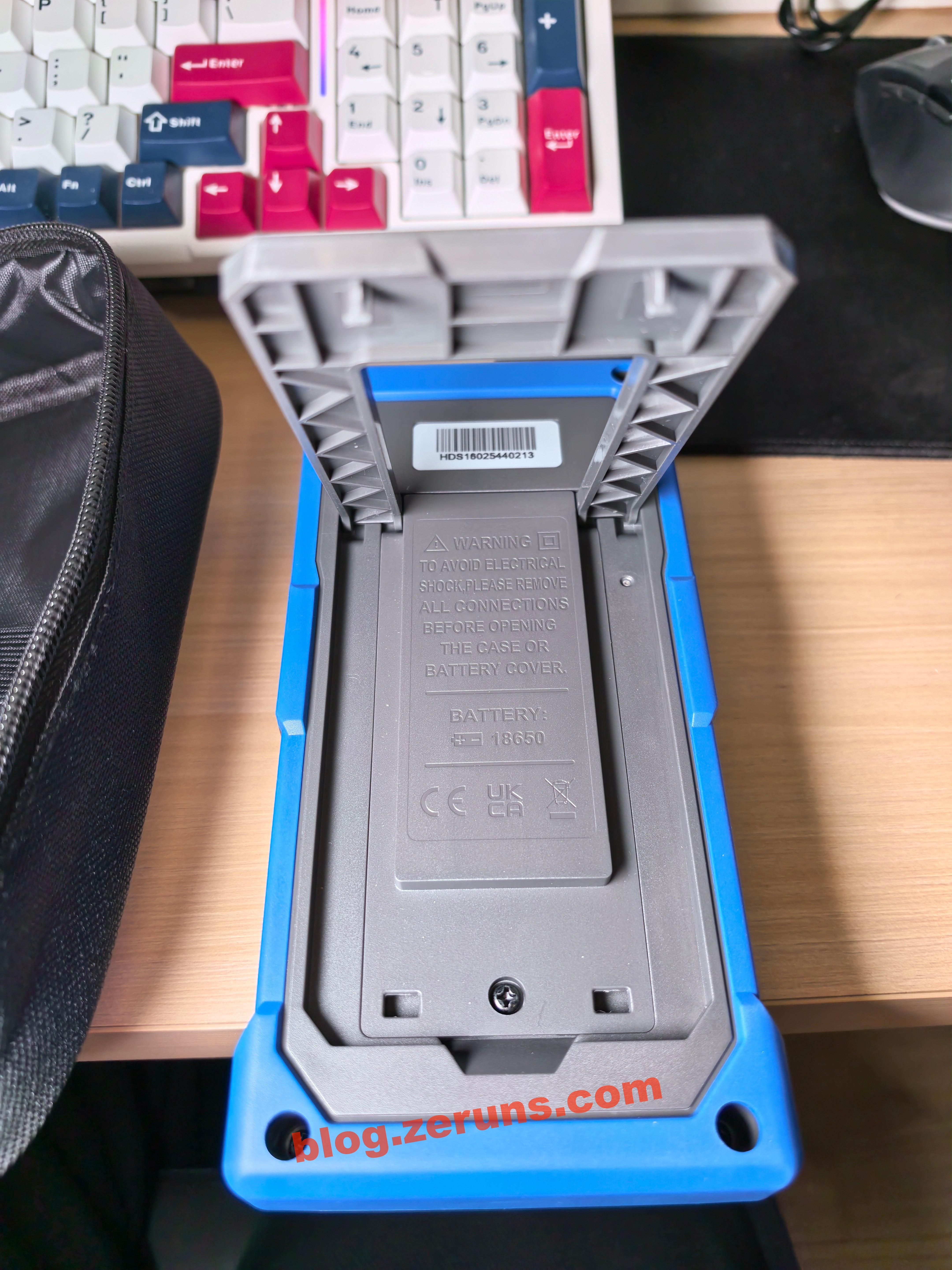
万用表背面,有支架,打开后可以立起来。
万用表用支架立起来的效果。
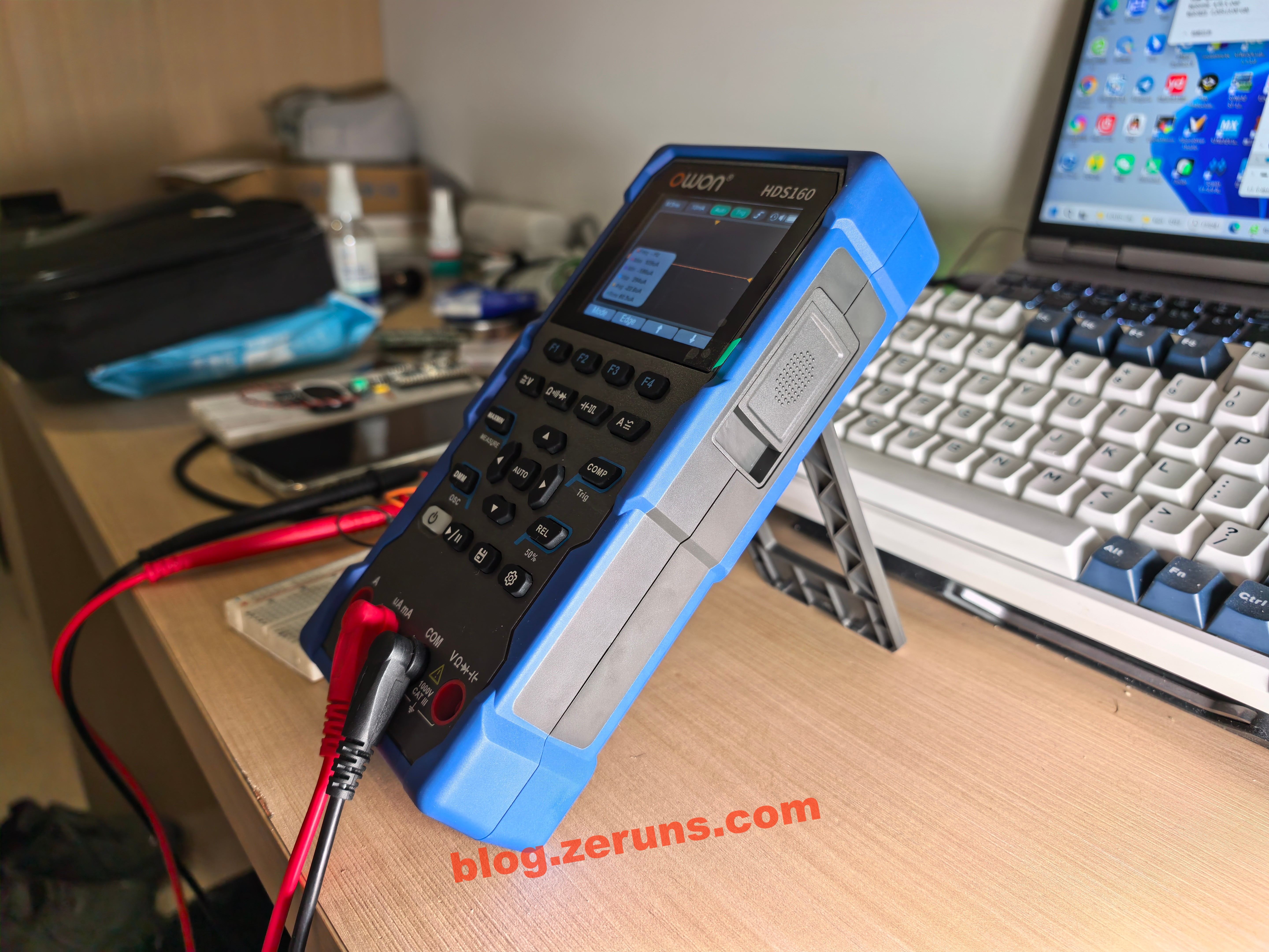
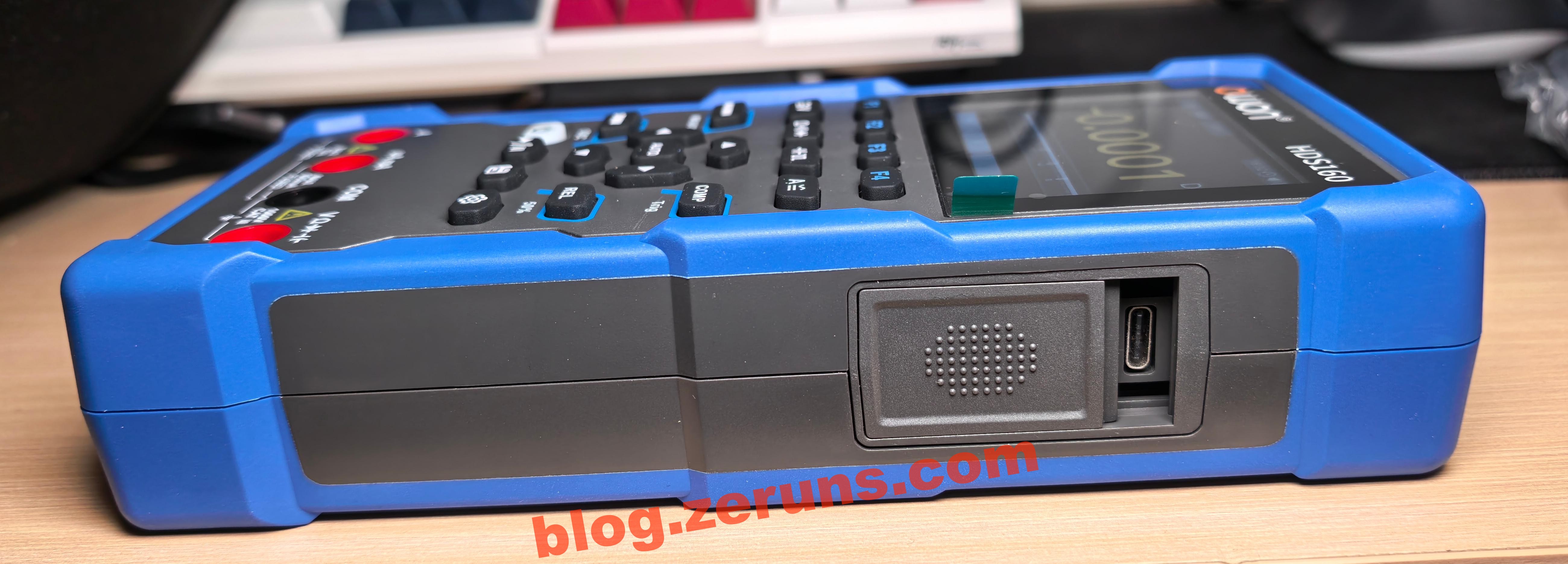
万用表侧面,有个TypeC口,可充电,插电脑上有个虚拟U盘可直接复制示波器的截屏出来,这个C口好像有点歪了(后面的拆解可以看到应该是贴片贴歪了),C口这里有个拨片,充电时把这个拨片拨下的时候会把万用表表笔接口挡住,不允许边充电边用。
简单测评
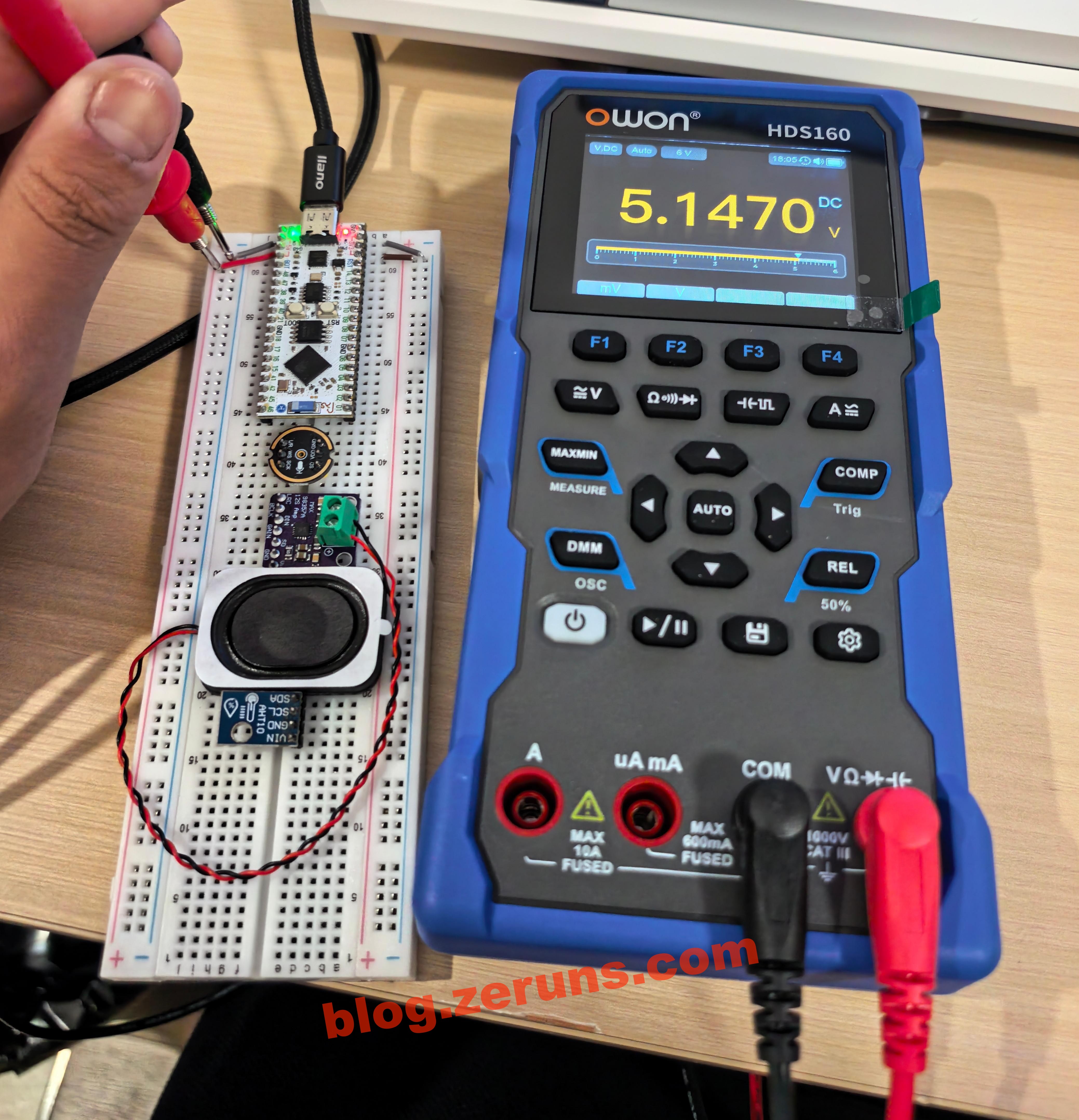
长按开机键开机,开机默认万用表DC电压档模式,暗色主题,按F1可切换毫伏档。下面表笔接口被挡住是因为把充电接口挡板打下来了。
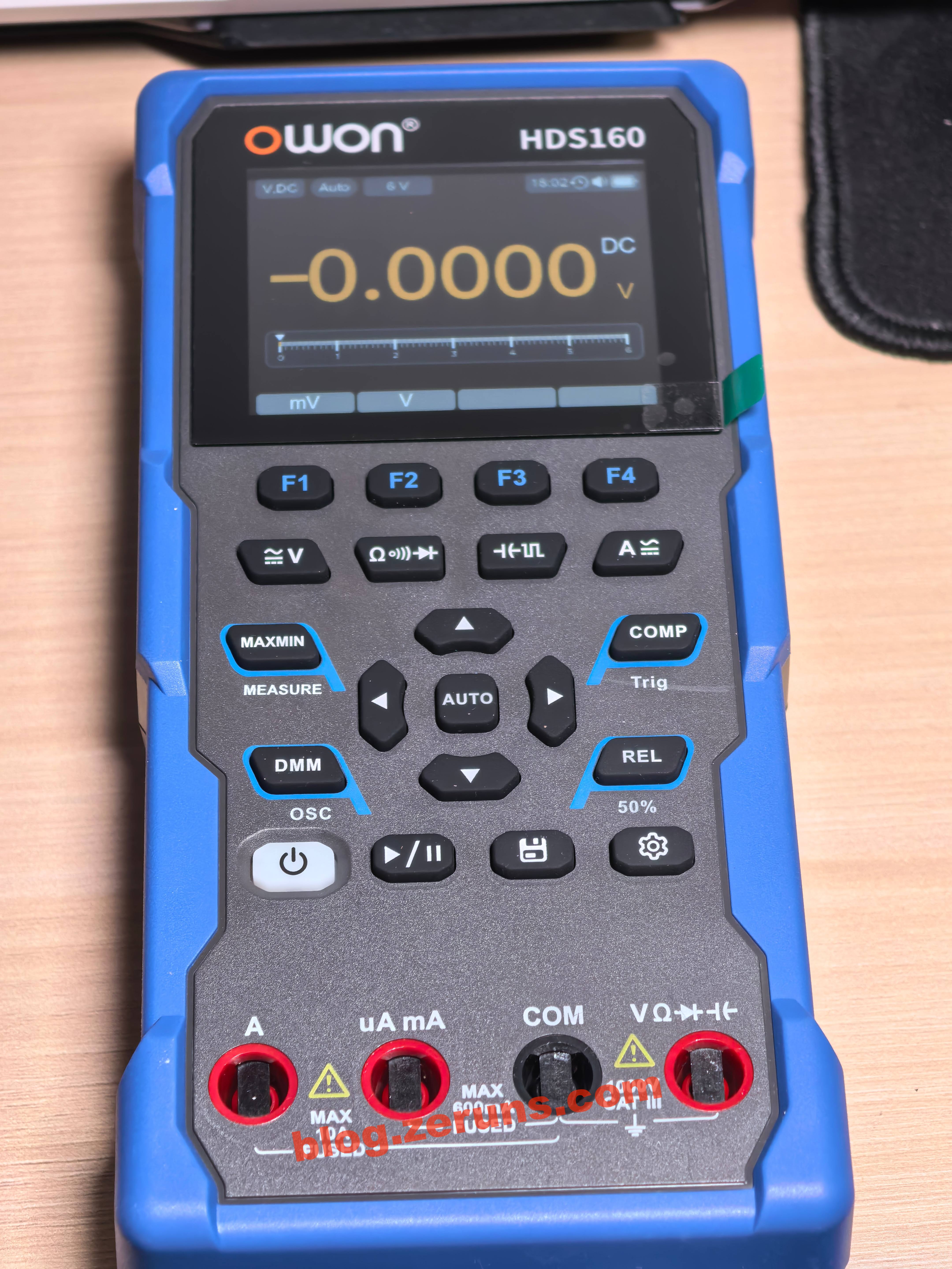
测一下电脑USB接口电压,5.147V,由于现在我在深圳这边,没带什么设备,所以也没法测它的精度。
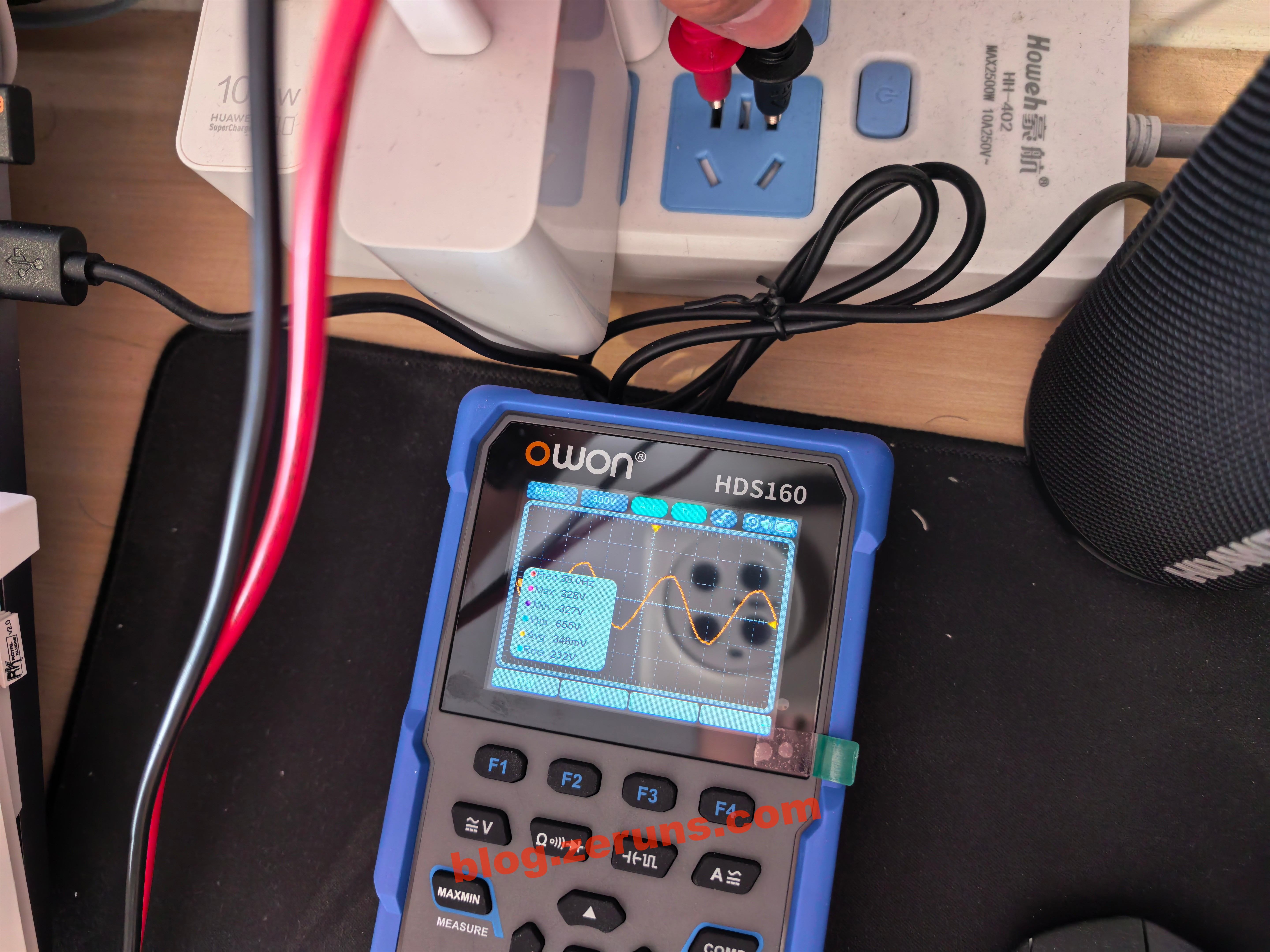
按DMM键进入示波模式,表笔直接插交流电插座,测得市电波形,频率50Hz,最大值328V,有效值232V。
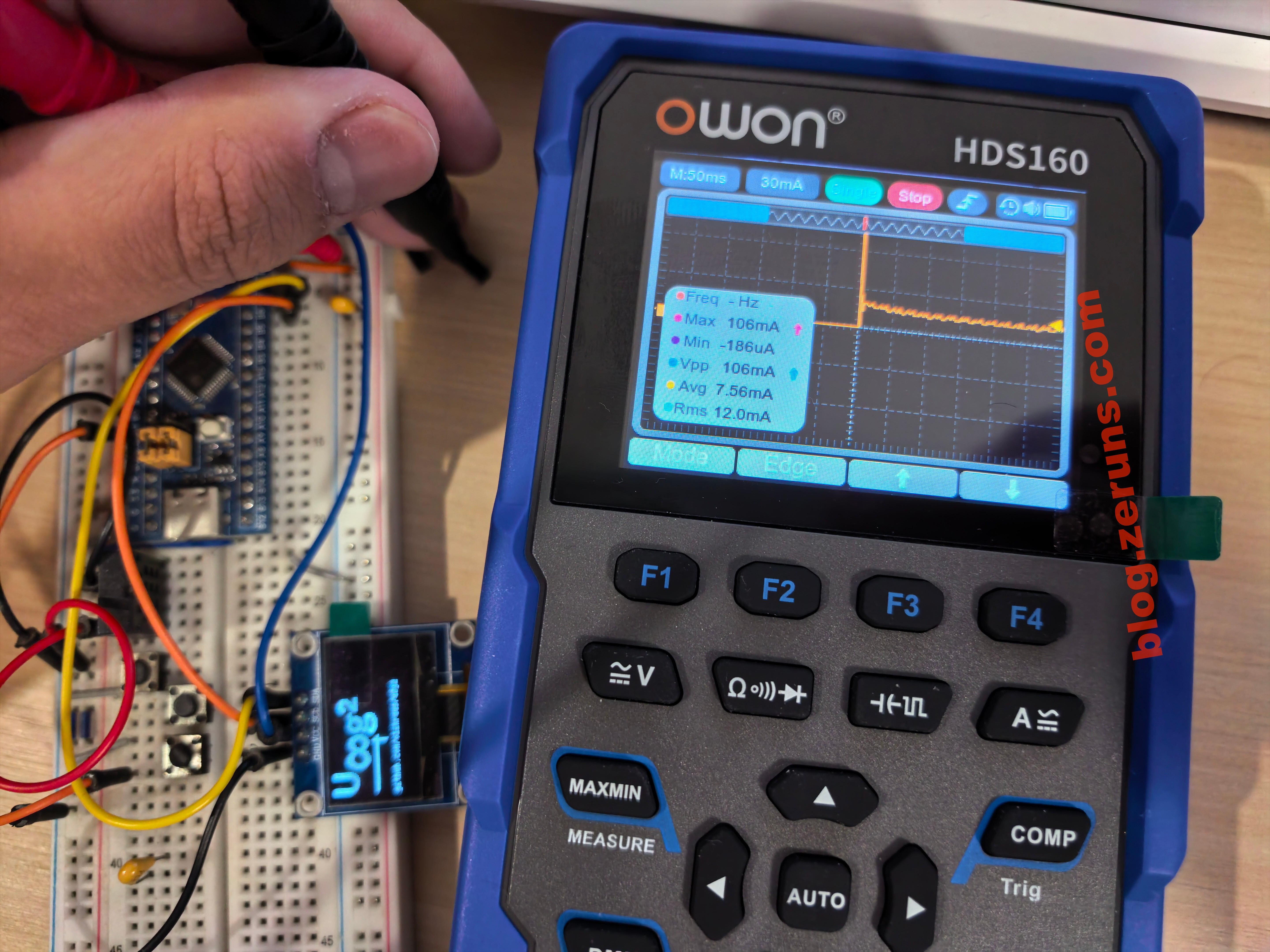
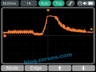
将表笔插入电流孔,自动切换到电流档,示波模式下可切换到单次触发,测出STM32F103单片机+OLED屏上电瞬间的电流波形,最大值106mA。
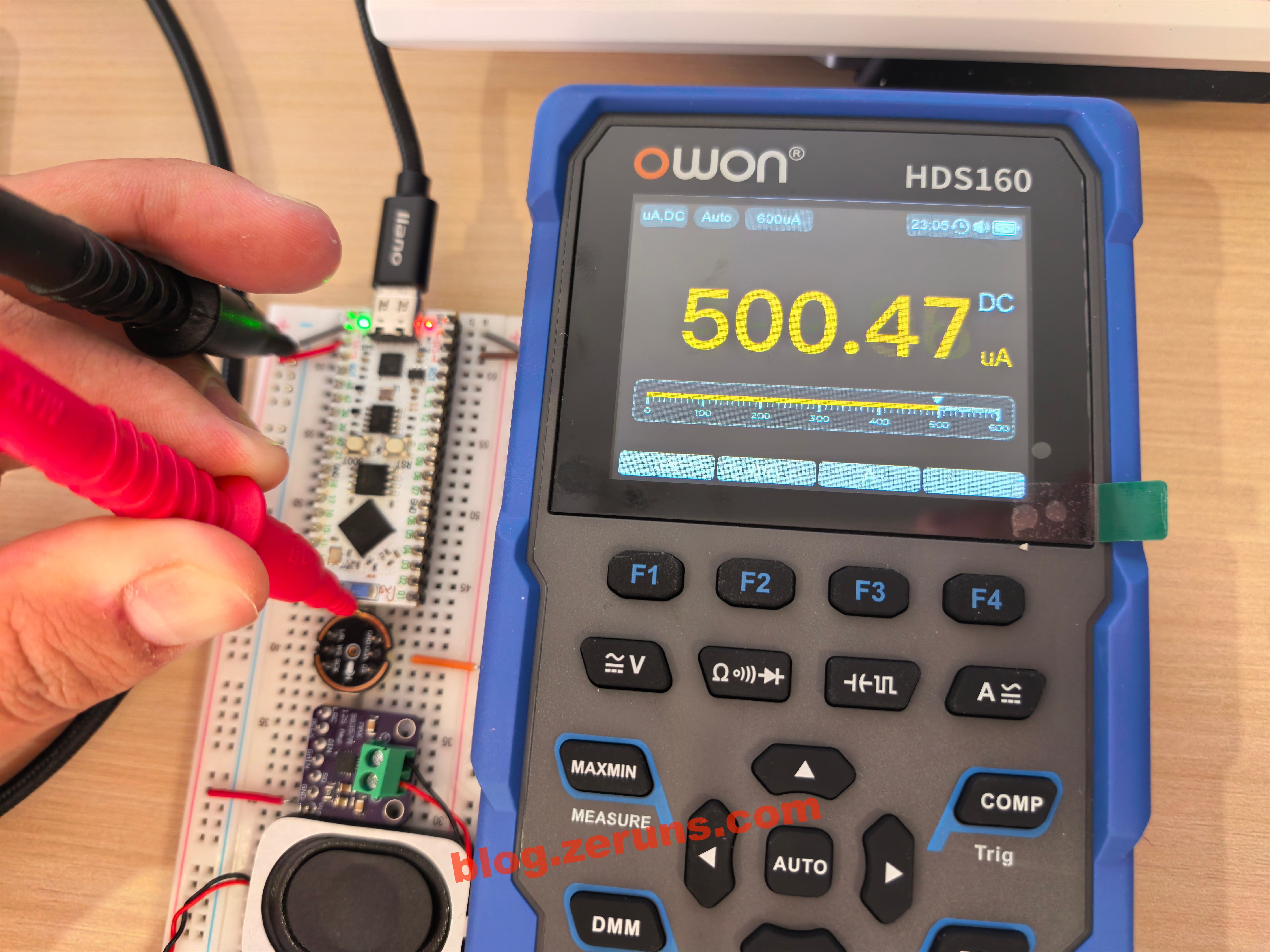
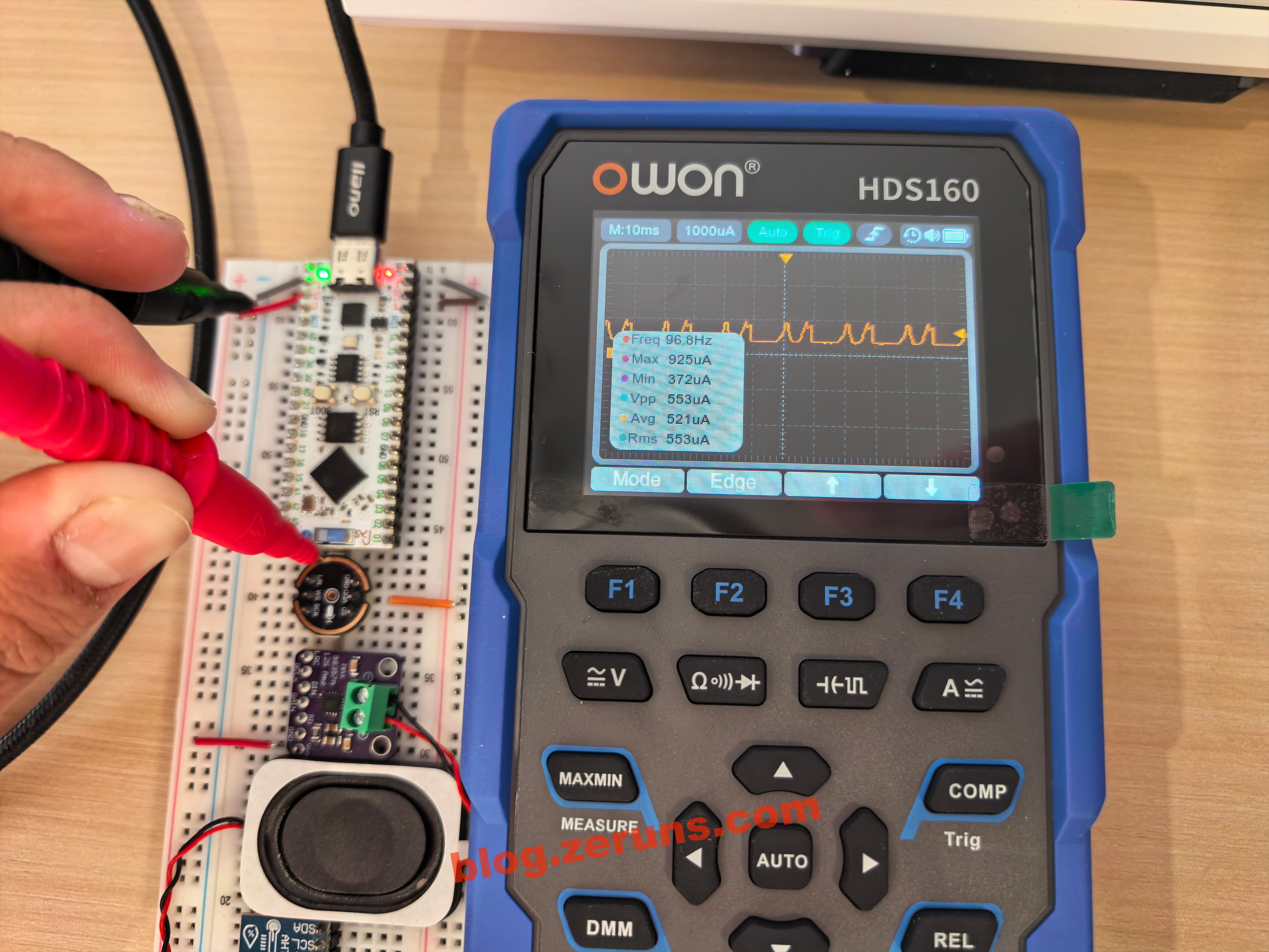
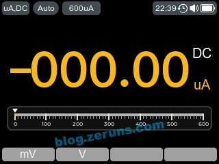
测量INM441数字麦克风的工作电流(无通信状态下,仅通电),下图分别是万用表模式和示波表模式的图,有效值500μA左右。
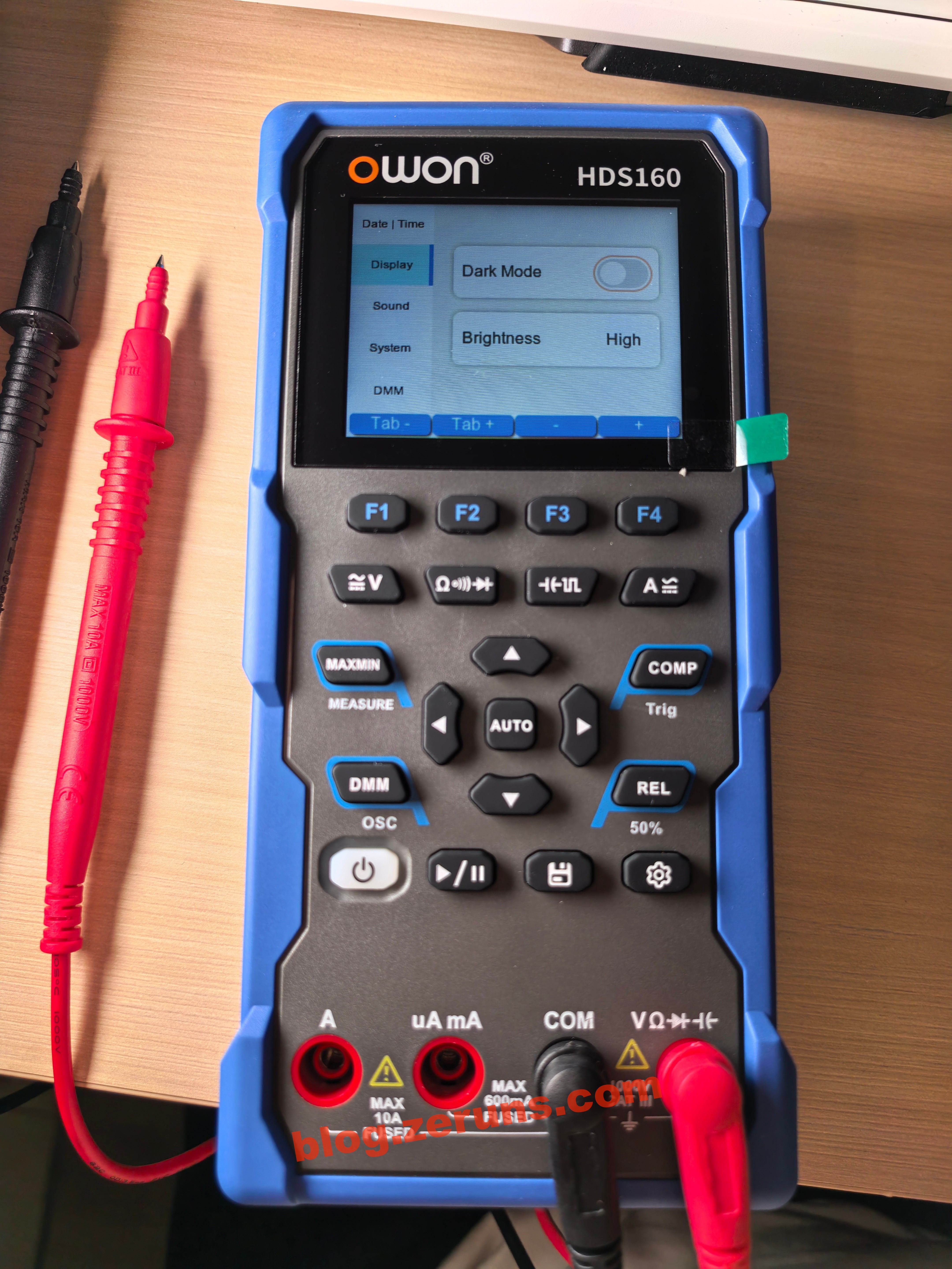
设置界面可切换亮色模式或暗色模式,亮色模式背景为白色,设置界面还可以设置系统时间、蜂鸣器是否开启以及音量大小、自动关机时间(最大30分钟)、蜂鸣档/通断档触发蜂鸣的电阻值。由于没有RTC电池,一旦拔电池,时间就会被重启,所以这个时间功能没什么意义。
看这个UI风格,应该用的是LVGL图形库。
基于STM32F407的LVGL工程模板(MSP3526屏幕),包含FreeRTOS版和裸机版:https://blog.zeruns.com/archives/788.html
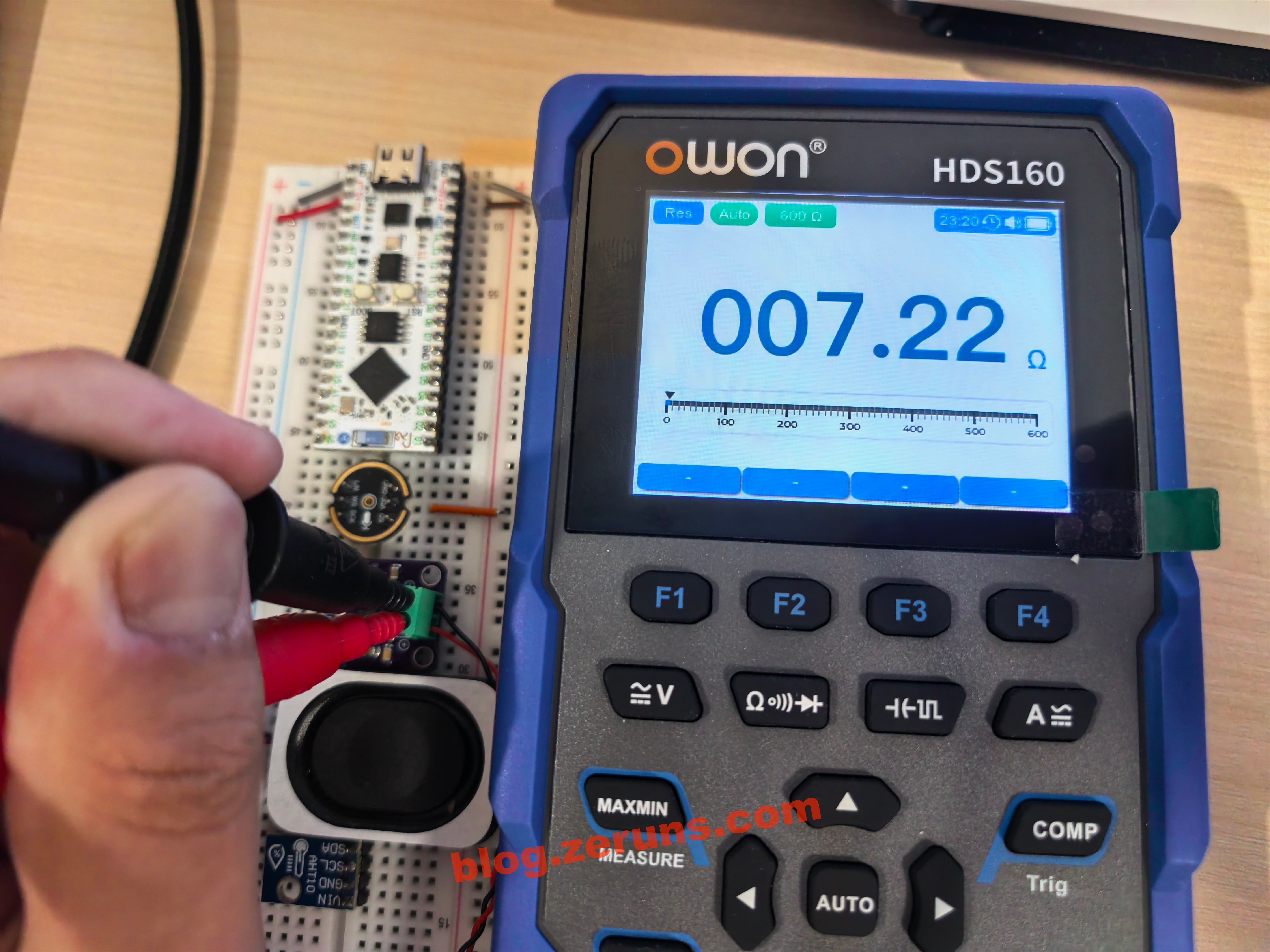
测量某个扬声器的阻值,测得7.22Ω。
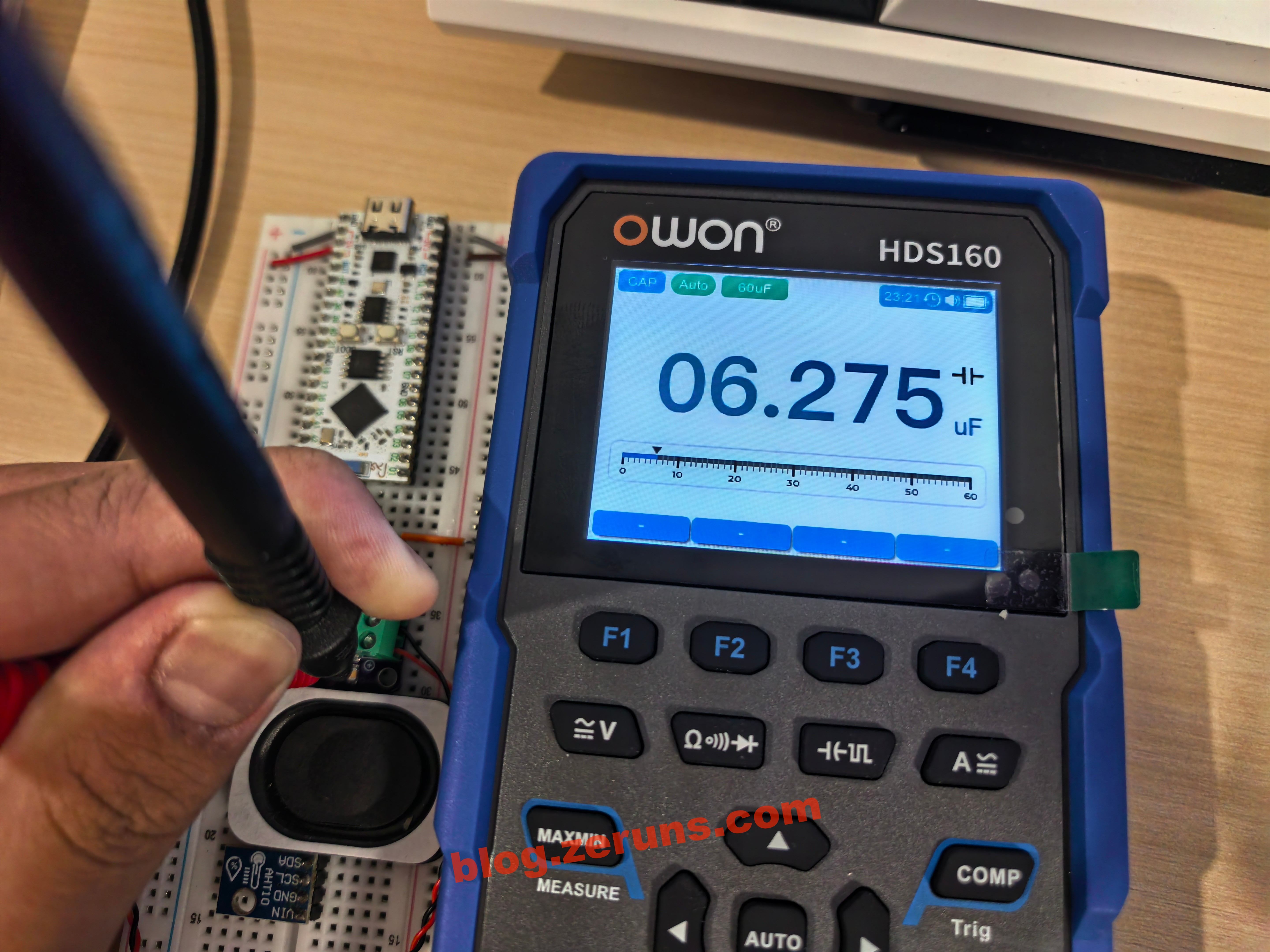
测量电容。
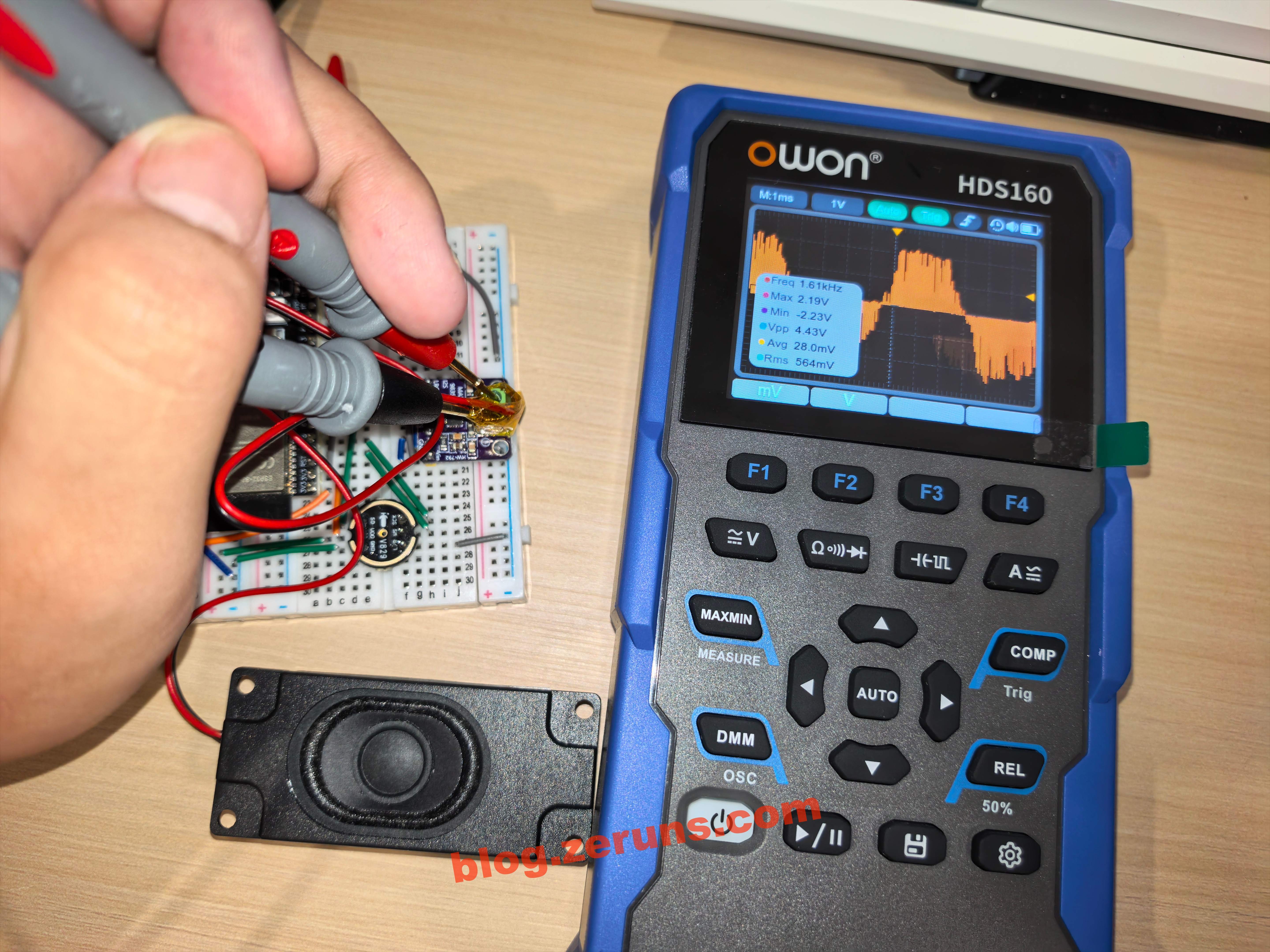
示波器模式测量MAX98357A输出的音频波形,应该是PDM调制的。
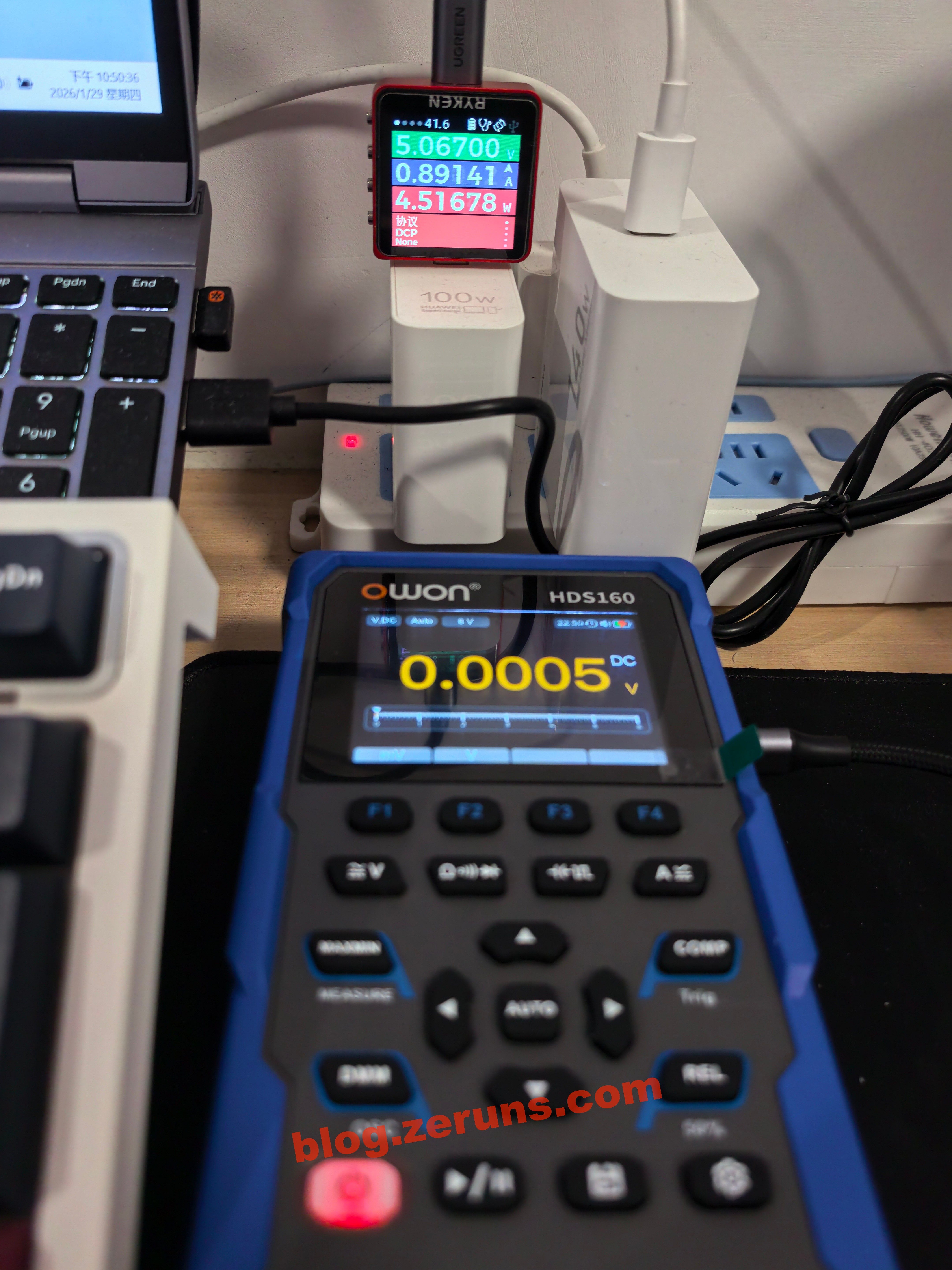
万用表充电功率4.5瓦左右。
还有截屏功能,C口连接电脑即可将截图复制下来,还算挺方便的,不过有个缺点就是示波器模式下的波形截图没有格线,不好判断数值。
拆解
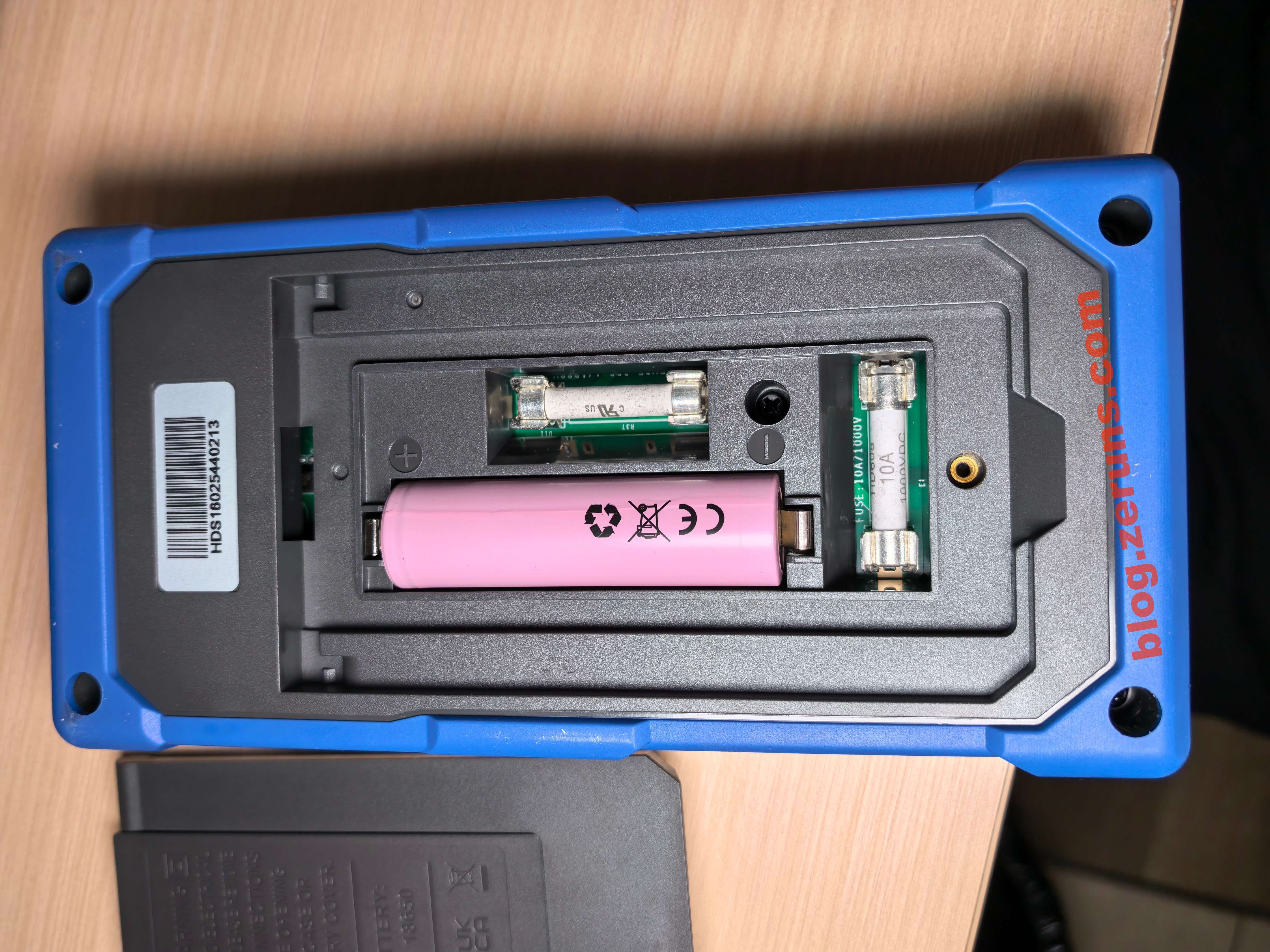
拧下万用表背后支架上的螺丝可拆下支架即可看到18650电池和两个保险丝,电池底下的保险丝是10A的,与电池并排的保险丝是600mA的,应该是毫安档的。
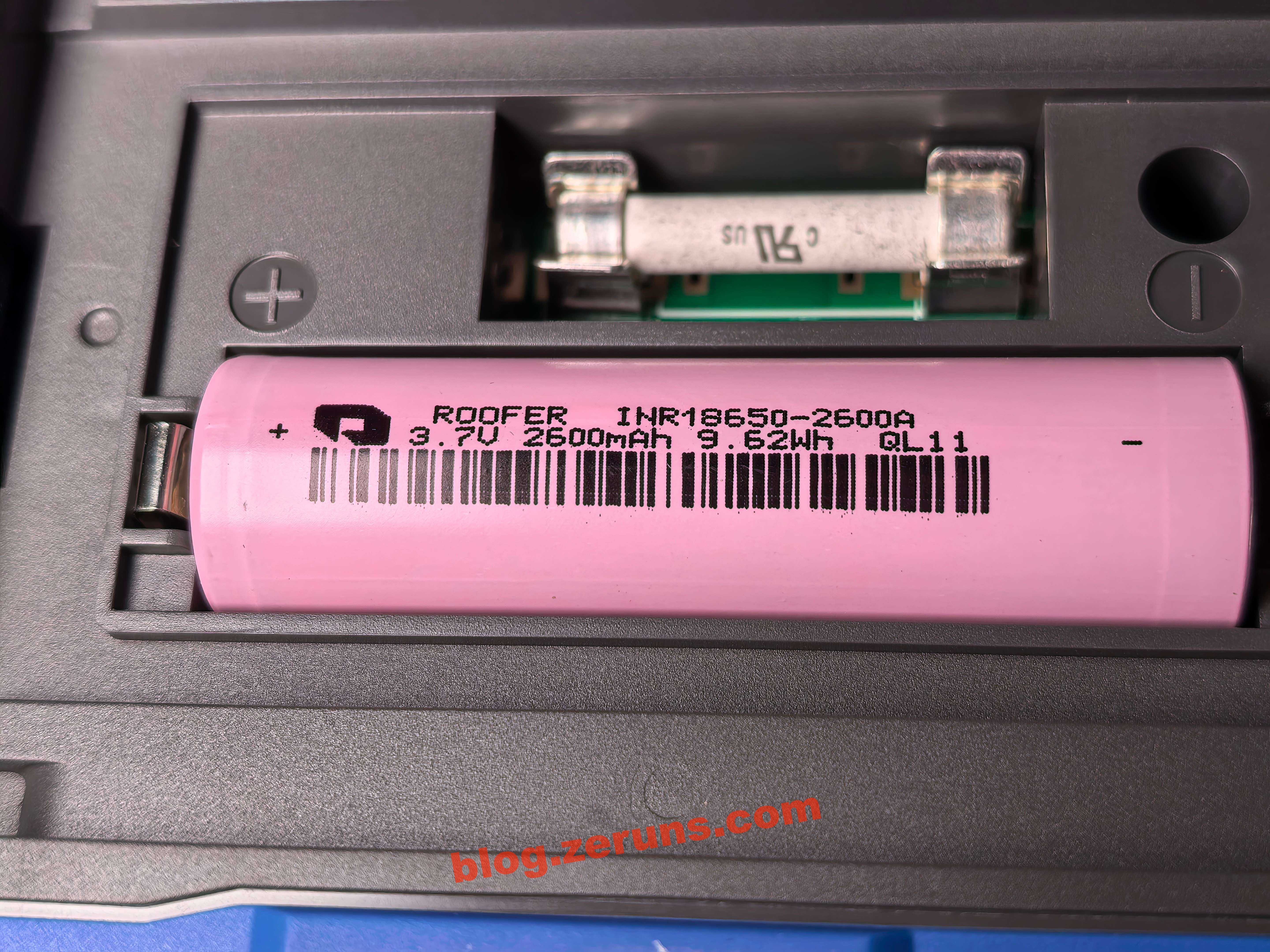
18650电池上标注着:3.7V,2600mAh,9.62Wh,
电池品牌是 路华(ROOFER),型号:1NR18650-2600A。
拧下四周的螺丝即可拆下万用表的底壳。
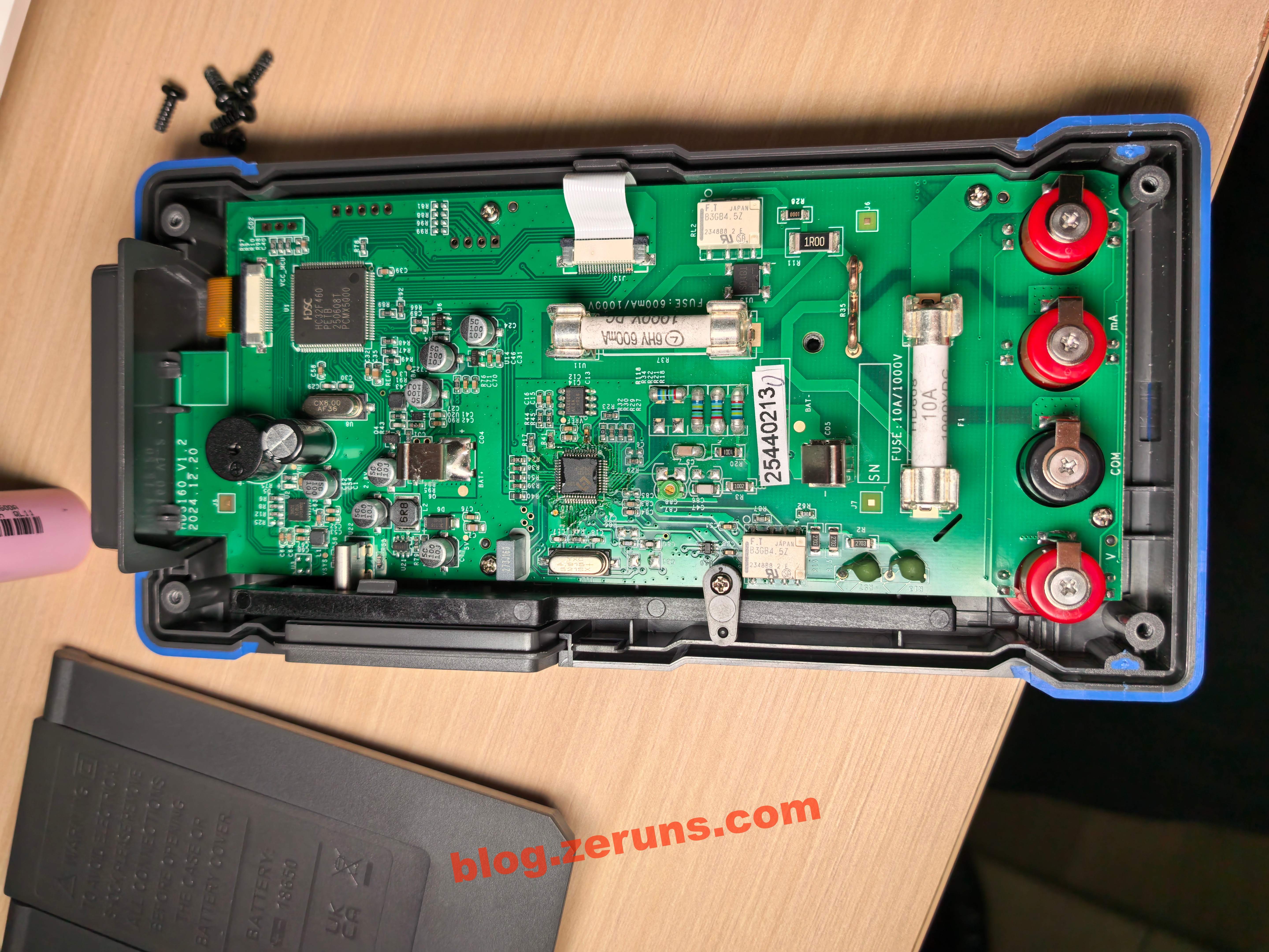
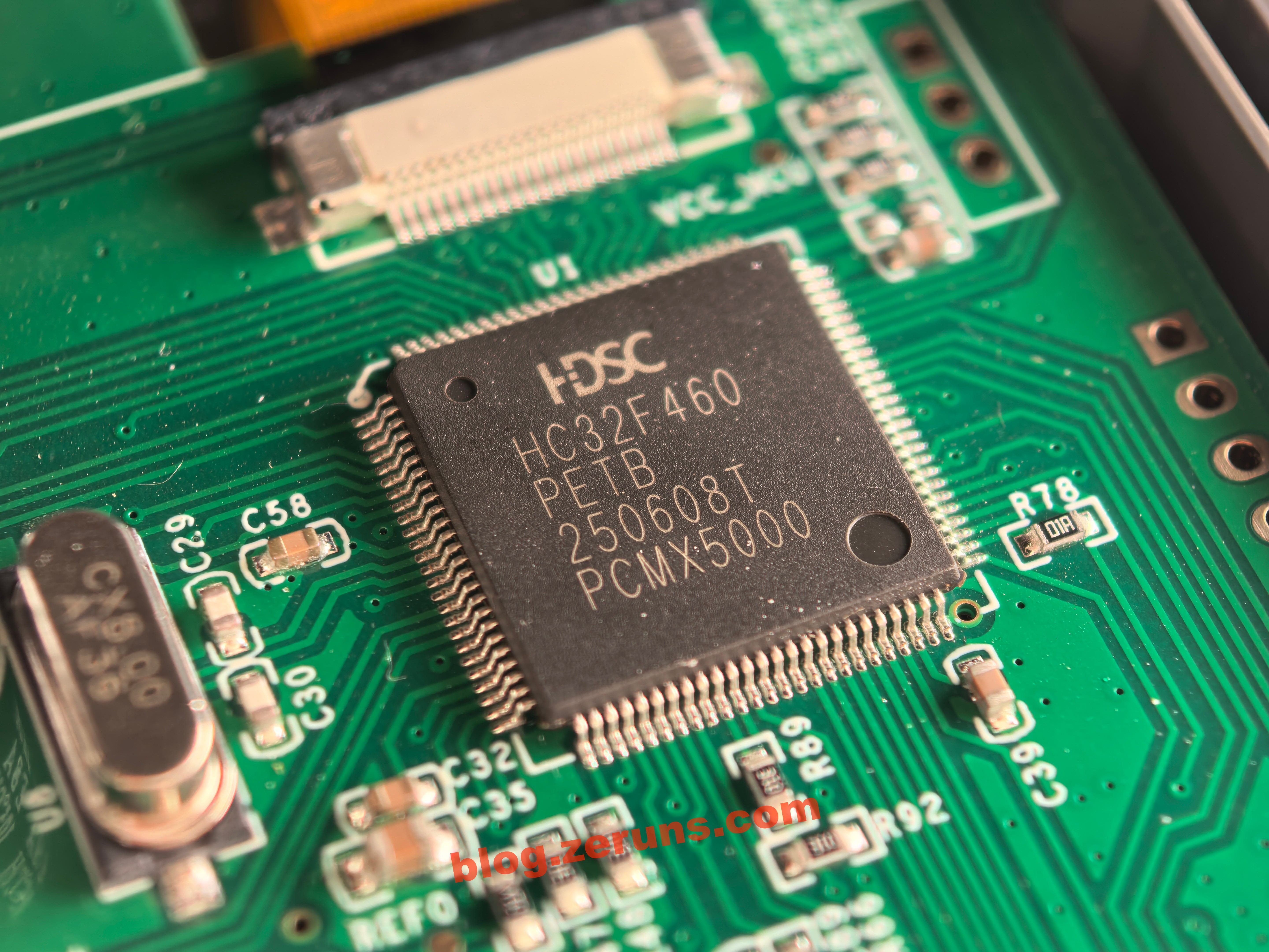
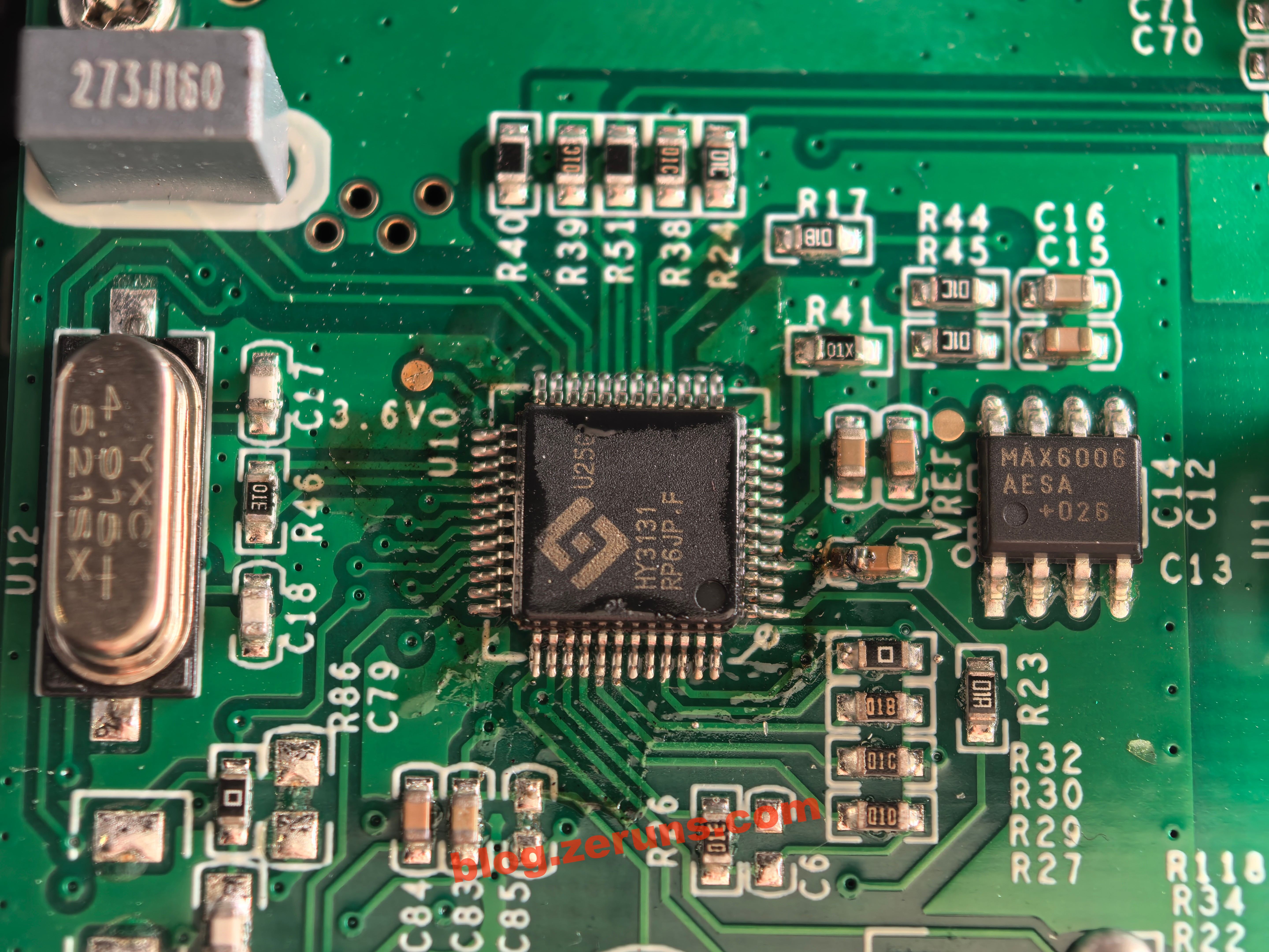
主控单片机型号为 HC32F460PETB,小华半导体的32位工业级MCU,采用Cortex-M4内核(含 FPU/DSP),主频200MHz,512KB Flash + 192KB SRAM,LQFP100封装。旁边的晶振为8MHz。
我猜测示波器功能应该是用主控单片机的内置ADC实现的,这款单片机有2个独立12bit 2MSPS ADC,1个可编程增益放大器(PGA)。
万用表芯片型号是 HY3131,紘康科技的高精度万用表模拟前端芯片,50000计数,内置24位Σ-ΔADC,集成真有效值/频率测量/峰值保持,SPI接口,LQFP48封装。
AI说万用表厂商会通过软件算法、量程校准和外围电路优化,让这颗芯片输出接近60000计数的显示效果,从而在产品宣传上标注60000计数。
万用表芯片右边的8脚芯片型号是 MAX6006AESA,这是ADI(原Maxim)的A等级超低功耗分流型精密电压基准,固定1.25V输出,初始精度±0.2%、温漂±30ppm/℃,工作电流<1μA,采用8引脚NSOIC封装,无需外接电容,适配低功耗精密测量、便携仪器、ADC/DAC基准应用。
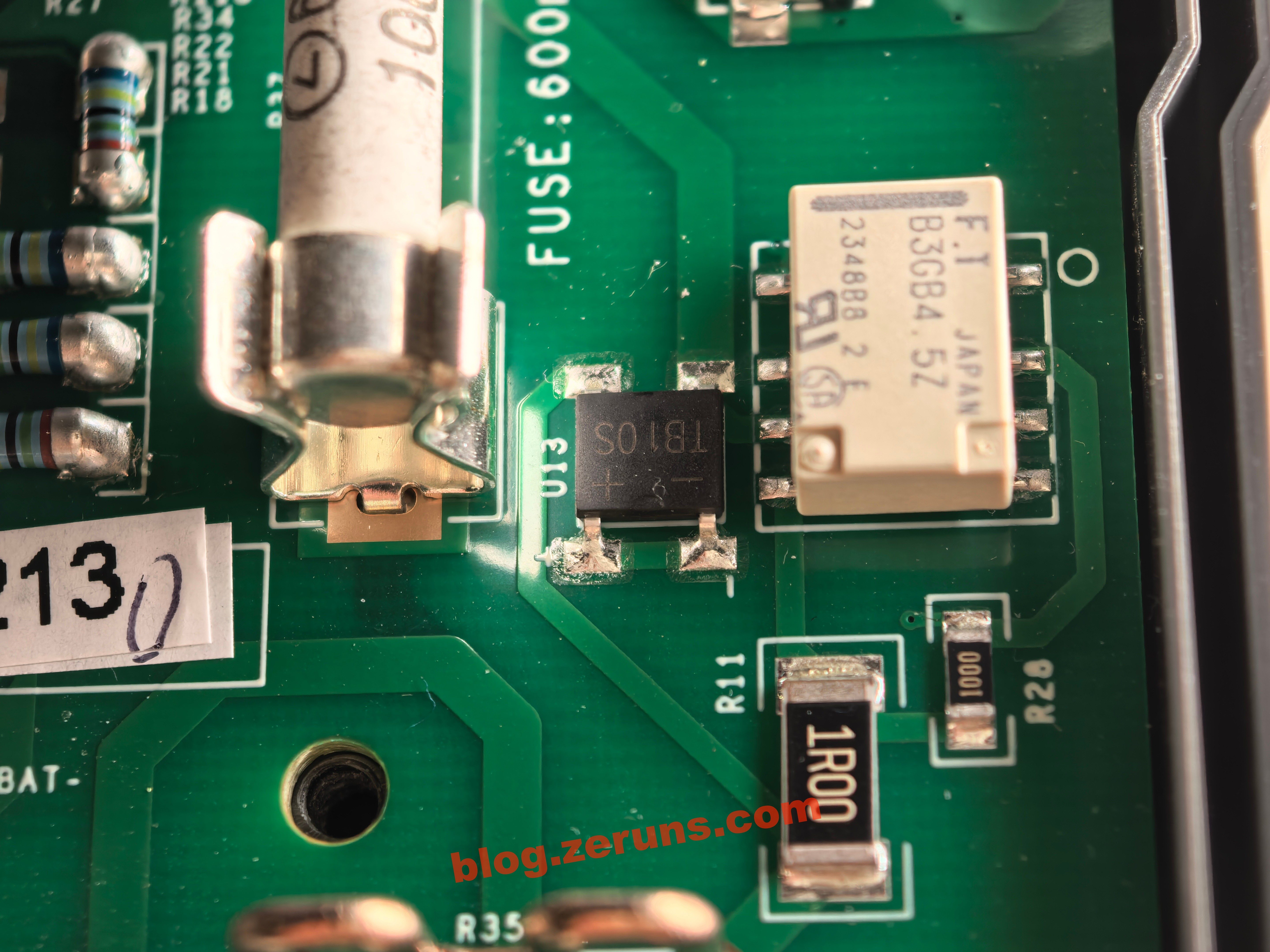
600mA保险丝旁边有一个型号为TB10S的整流桥,不知道干啥用的,有没有懂的朋友可以在评论区说说。
旁边还有个型号为B3GB4.5Z的继电器,富士通(Fujitsu)的双稳态锁存型超薄信号继电器,线圈 4.5VDC/100mW,DPDT(2C)触点,额定1A/30VDC、0.3A/125VAC,SMD封装7.2×10.6×5.25mm,重0.85g,高频特性优,绝缘强度1500VAC,RoHS合规,适用于高密度信号切换场景。
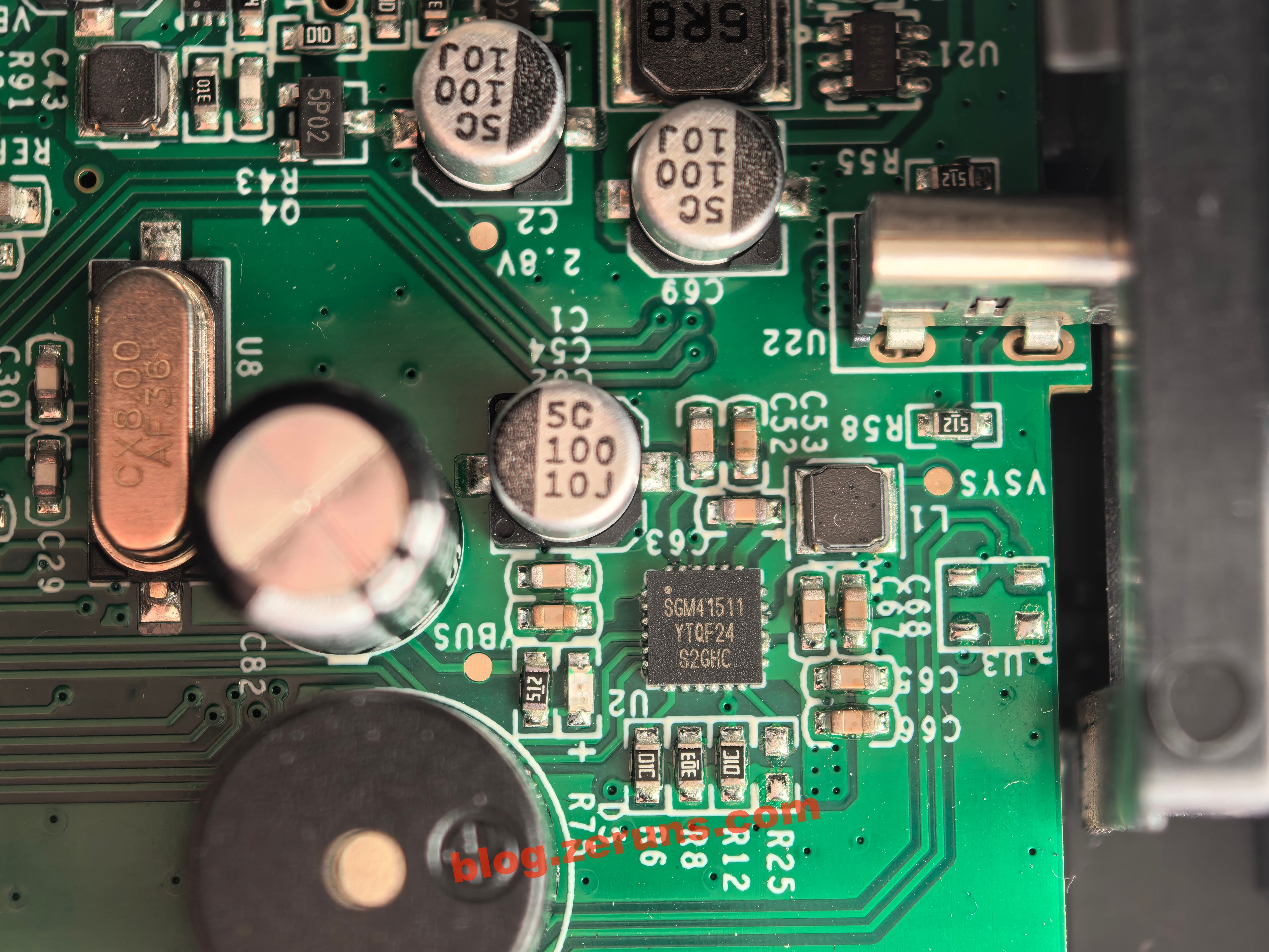
Type-C口旁边的一个芯片型号为SGM41511,这是圣邦微I2C可编程3A单节锂电充电与NVDC电源路径管理芯片,集成4路功率开关与转换器,支持USB/OTG、宽输入适配、DPM动态电源管理,具备JEITA温控、过压/过流/热保护等功能,TQFN-4×4-24L封装。
看手册,这款芯片是支持5V/2A输入的,实测充电电流却只有5V/0.8A,应该是设置了限流,可能用的电池比较差,不支持高点的充电电流。
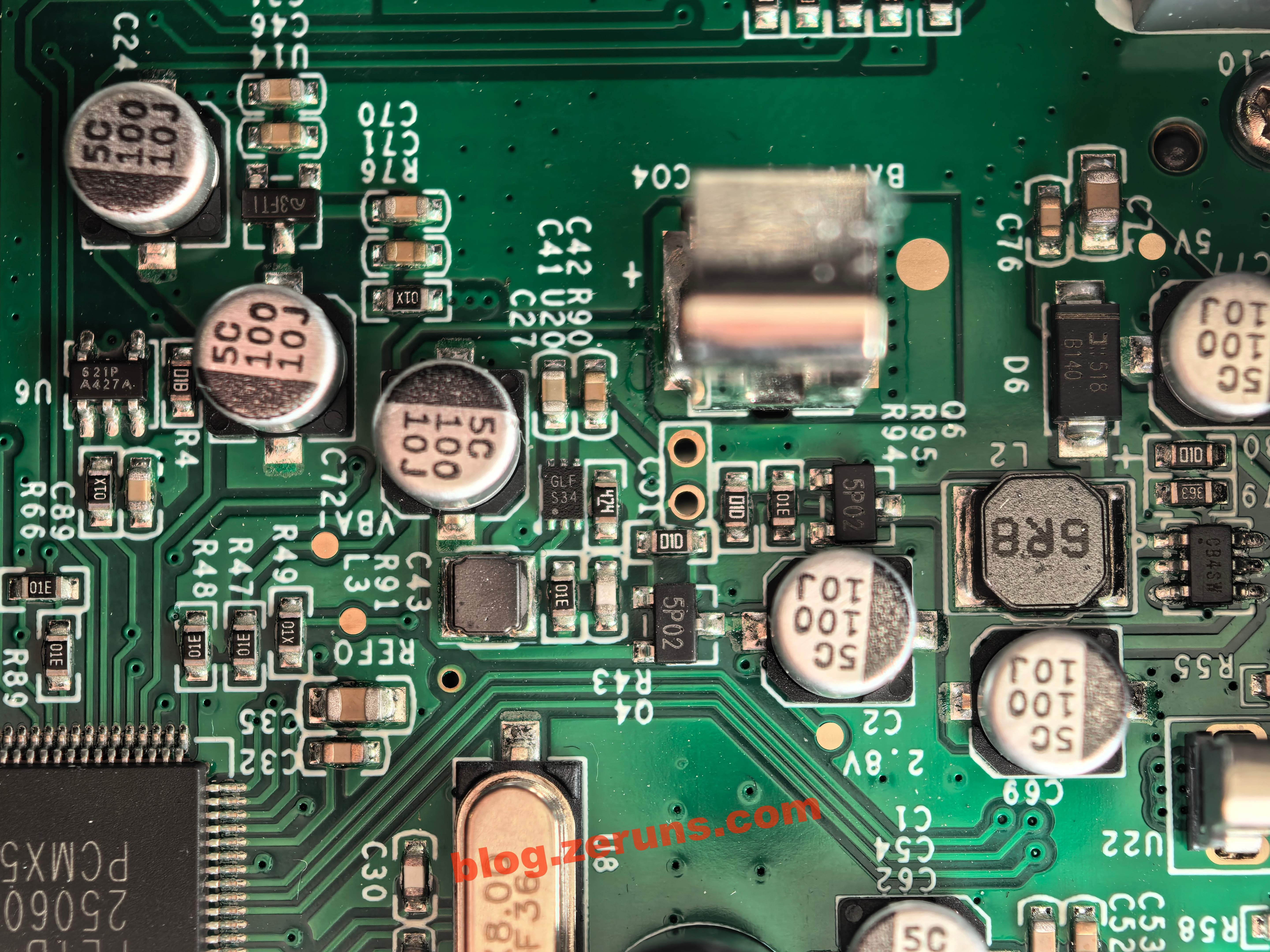
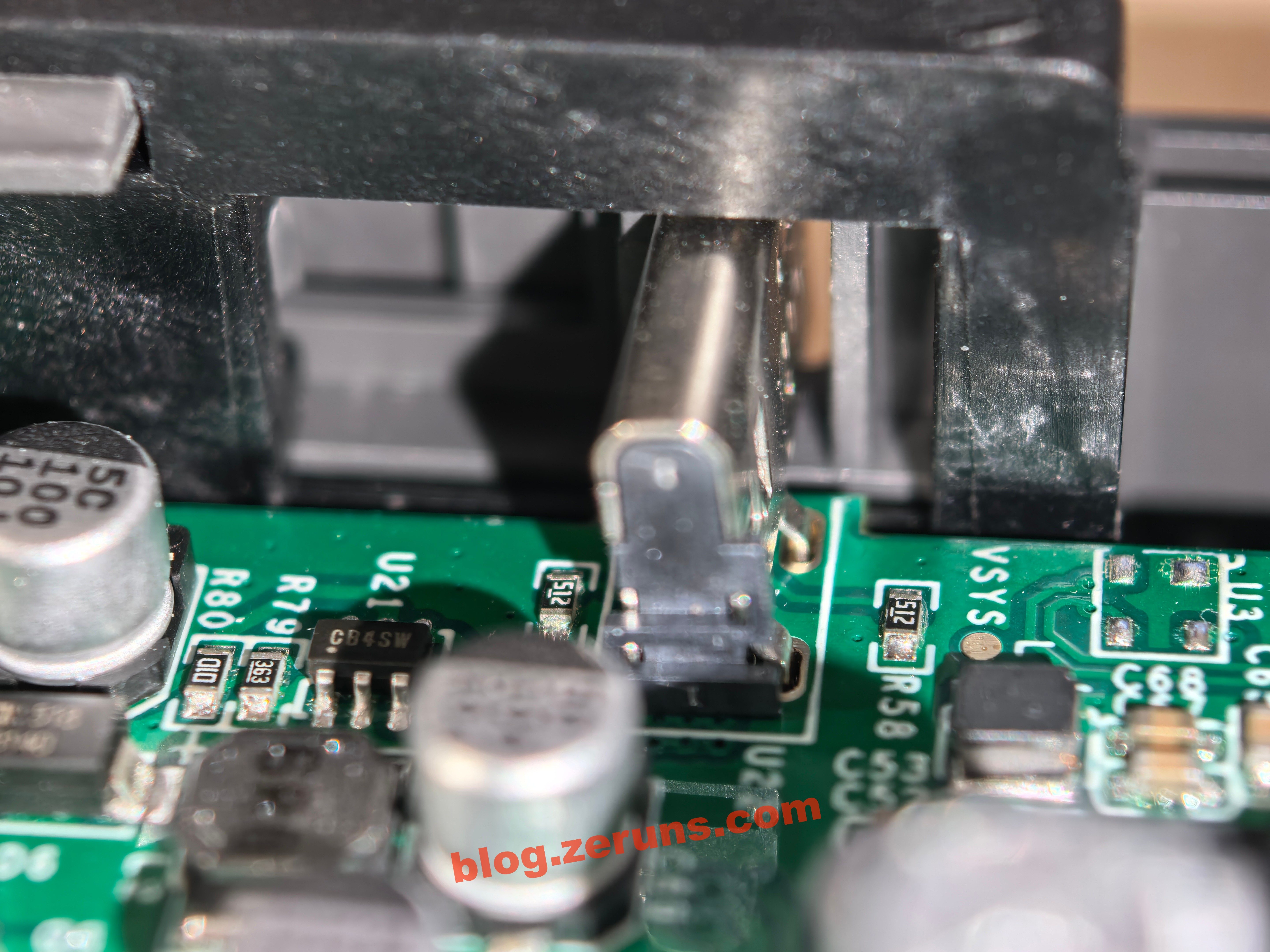
一些小芯片和一堆电解电容,以及两个电感,这一部分应该是DCDC电源,提供各种电压给电路各部分,芯片丝印分别有 S21P-A427A、3FT1、GLF-S34、5P02、CB4SW。
拆下万用表主板,背面有LCD屏幕,还有一块键盘小板,都通过FPC排线连接。
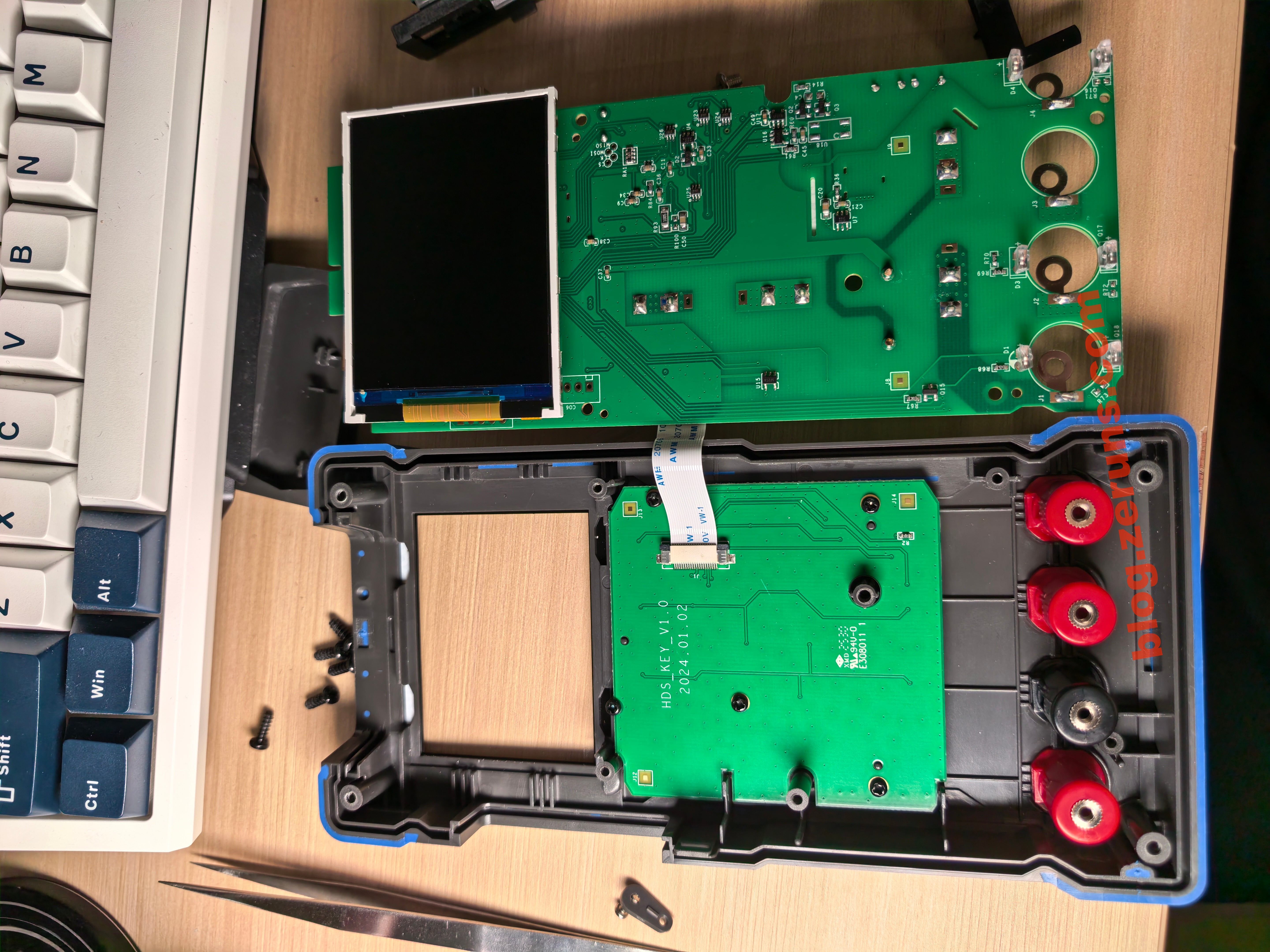
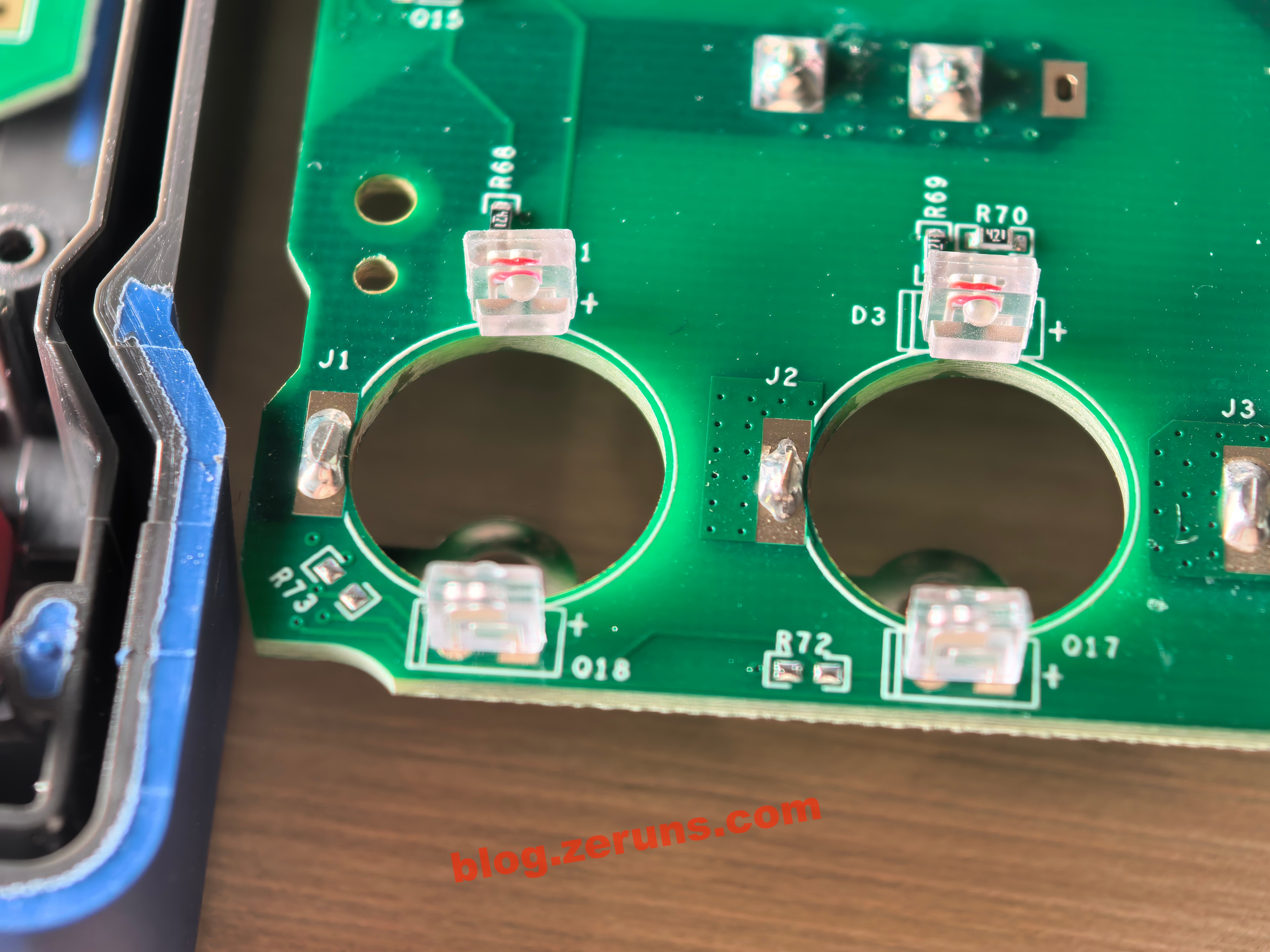
万用表表针插孔上都有一对应该是红外对管(红外发射和接收)的元件,应该就是靠这个识别插入哪个孔来自动切换档位,这个设计不错。
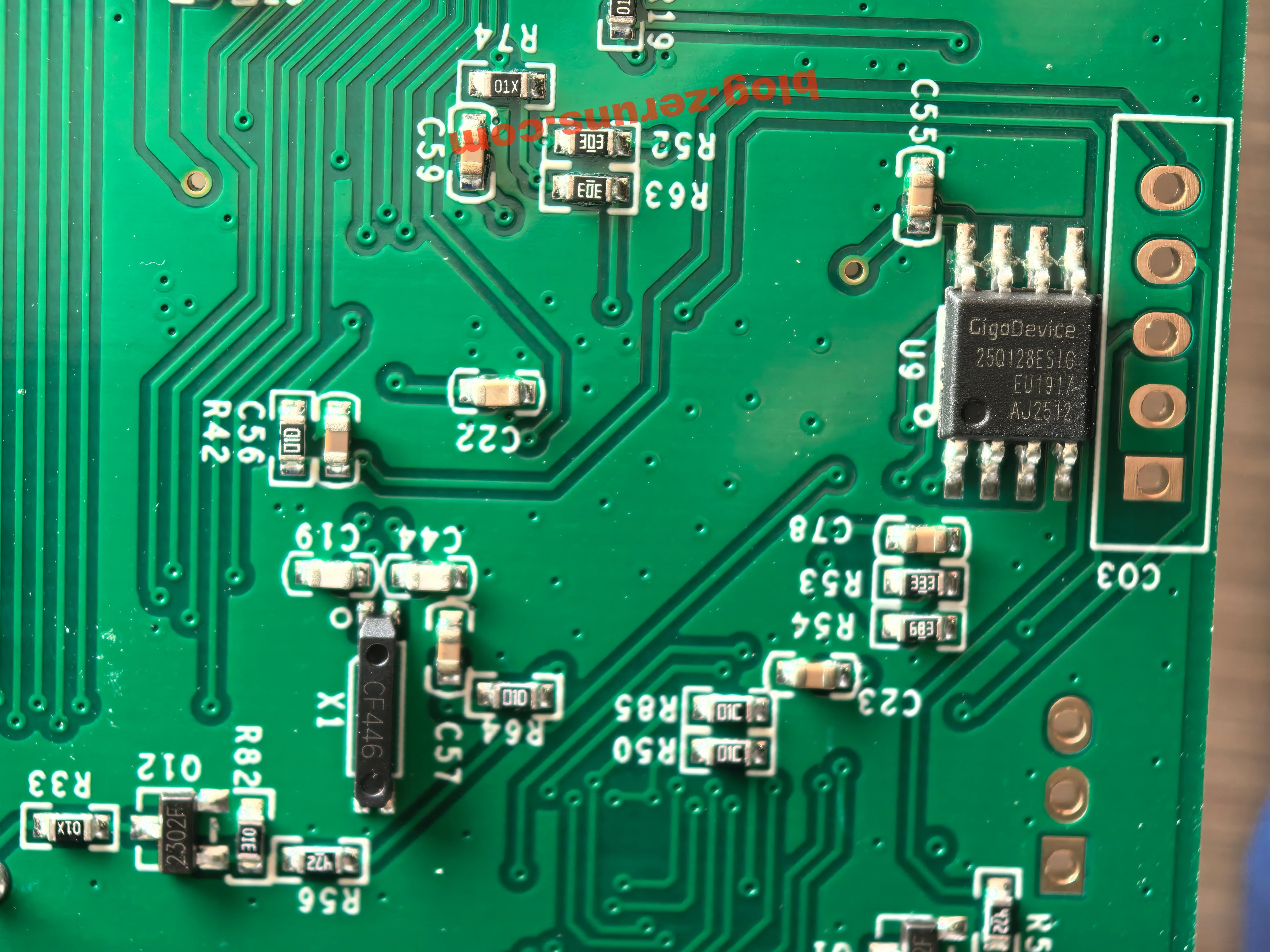
主控MCU背面有一个型号为GD25Q128ESIG的芯片,这是兆易创新出品的128M-bit(16MB)SPI闪存芯片,采用 SOP8封装,支持标准/双/四SPI接口,工作电压2.7~3.6V。我猜应该是用来存图形库相关资源。
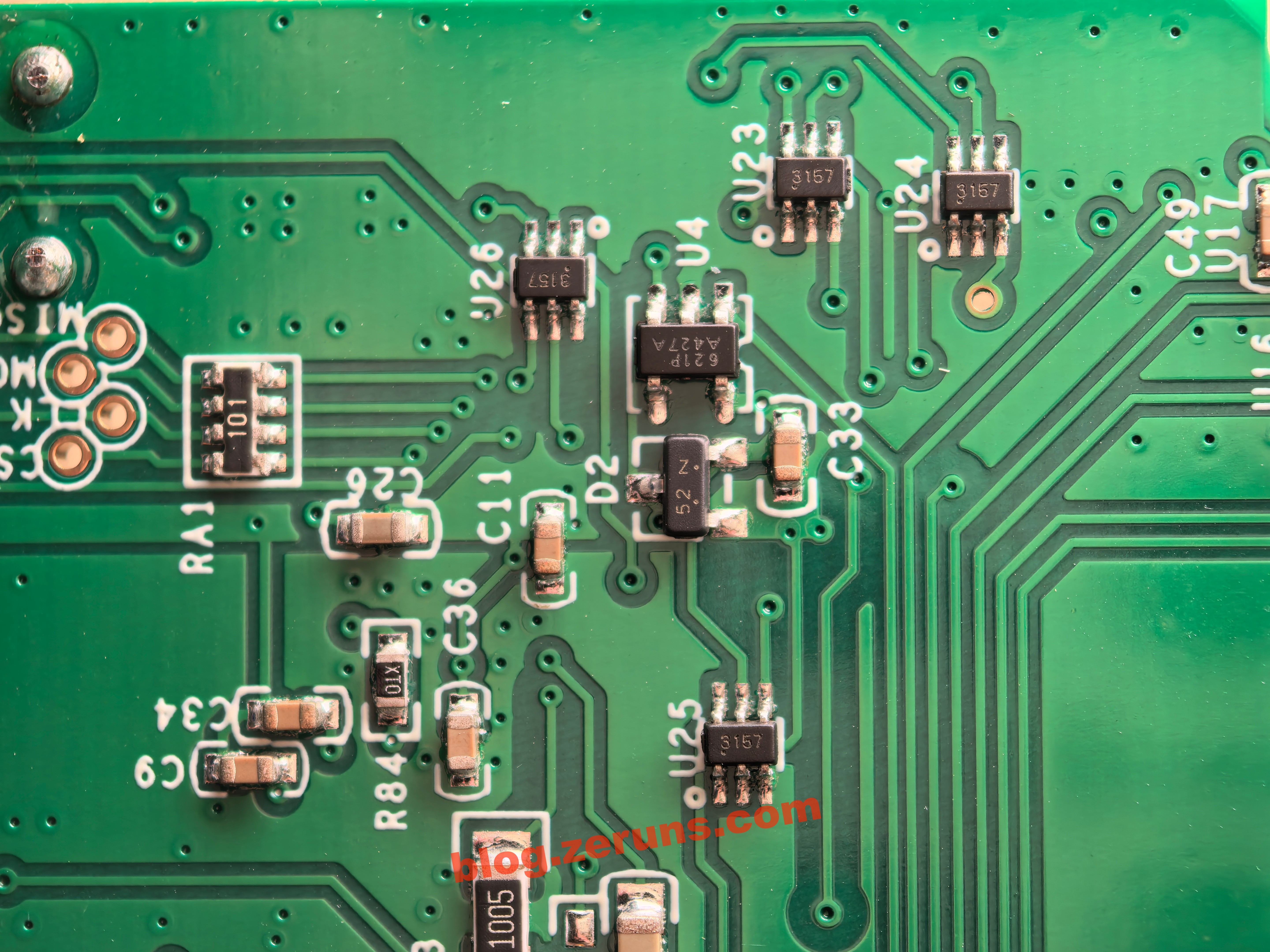
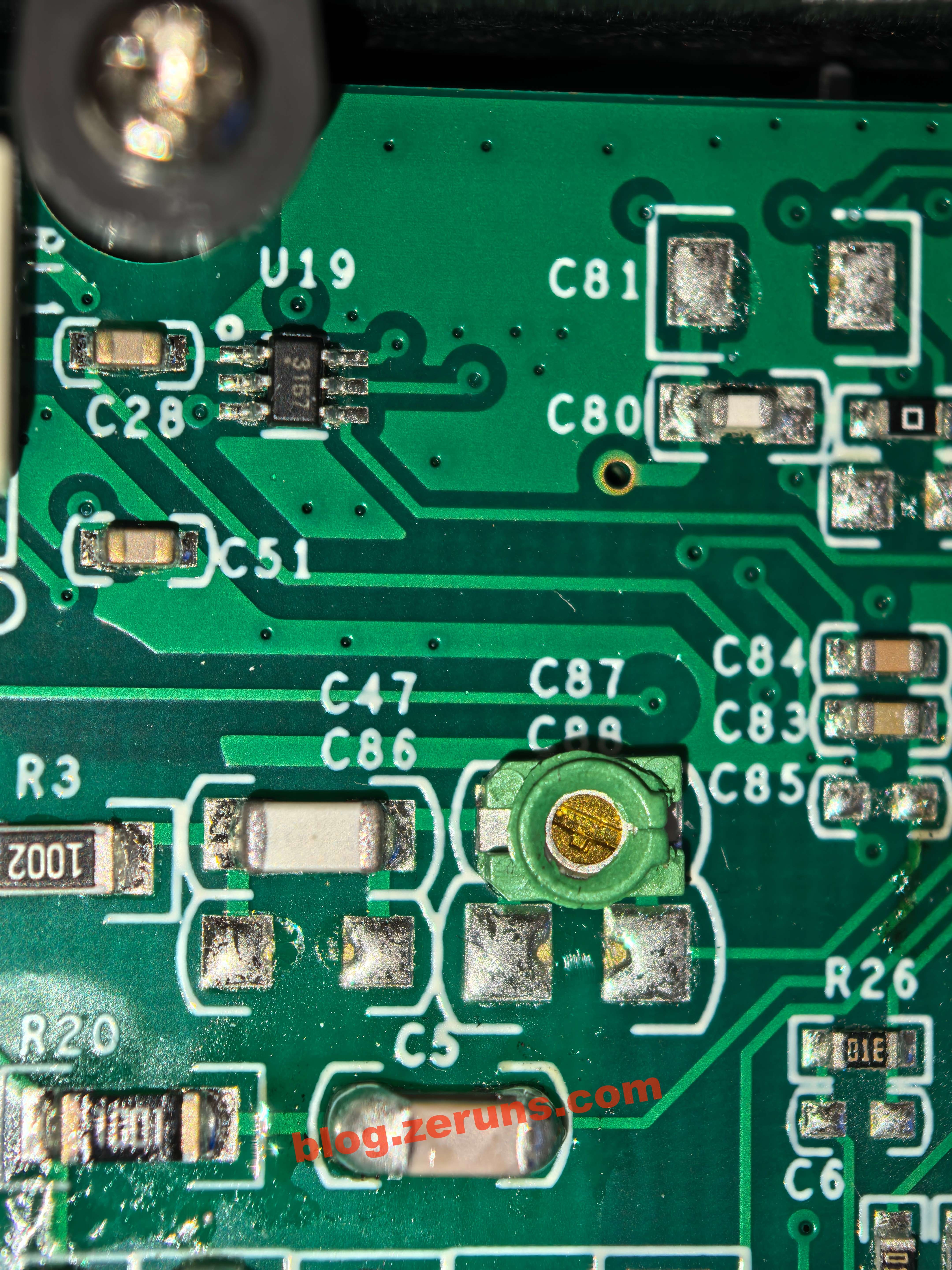
还有一些应该是信号处理或模拟开关之类的芯片,芯片丝印分别有 3157、621P-A427A、52N。
键盘小板,薄膜按键。
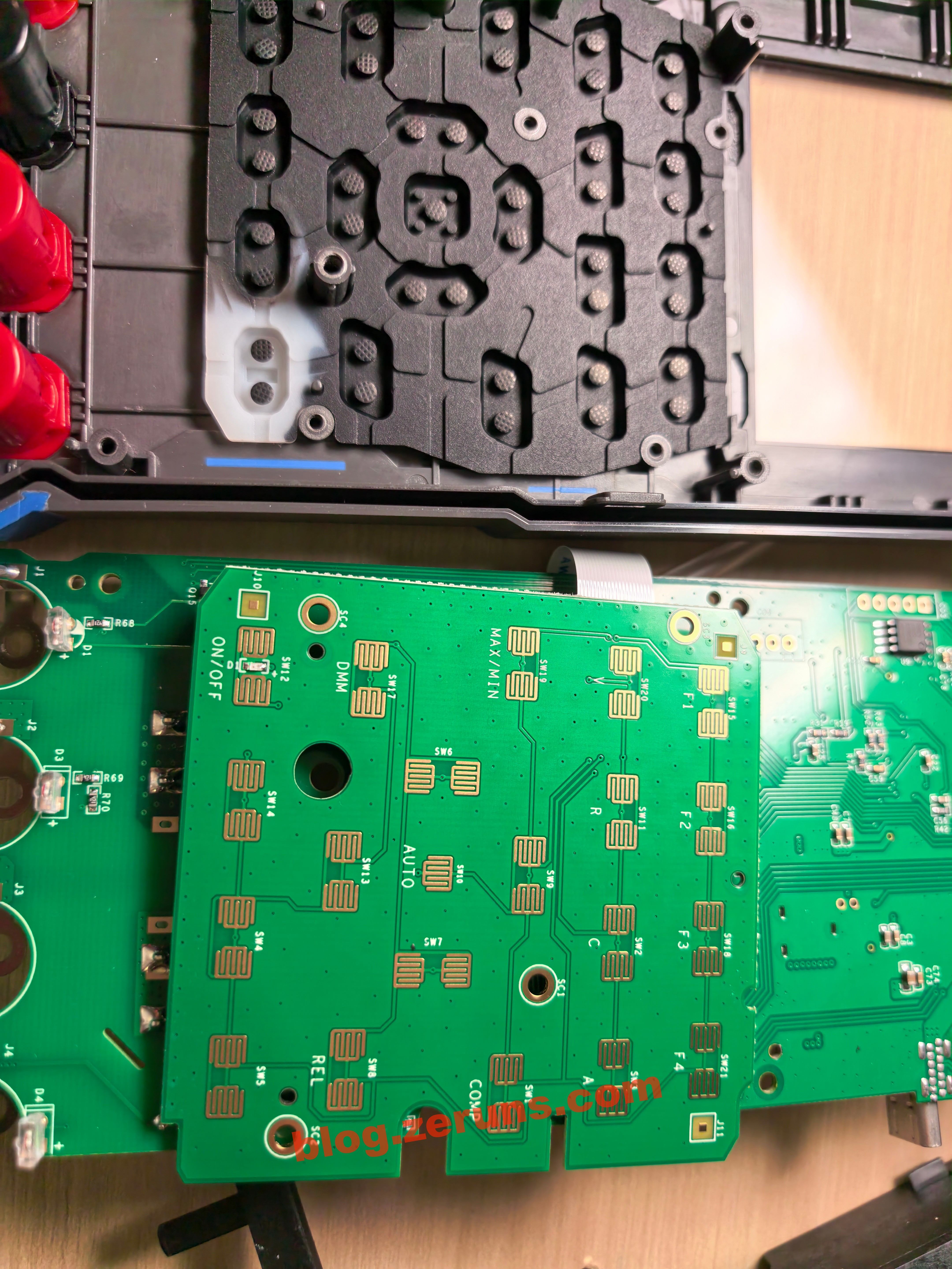
还有一些可调电容,应该是用来校准的。
C口焊歪了。
推荐阅读
- 高性价比和便宜的VPS/云服务器推荐: https://blog.vpszj.cn/archives/41.html
- Discourse论坛搭建教程,零基础部署Discourse开源社区论坛网站:https://blog.zeruns.com/archives/919.html
- 【开源】24V3A反激式开关电源(基于UC3842,含电路和变压器参数计算过程):https://blog.zeruns.com/archives/910.html
- 基于STM32的同步整流Buck-Boost数字电源 开源: https://blog.zeruns.com/archives/791.html
- 避雷淘宝某款ESP32S3开发板,WiFi信号极差,疑似没做阻抗匹配:https://blog.zeruns.com/archives/924.html
English Version of the Article: https://blog.zeruns.top/archives/83.html