After pulling IO0 low, power cycle the module to enter flash mode.
When using the ESP8266 FLASH DOWNLOAD TOOL to flash AT firmware, encountering the “Waiting for power-on sync” message usually occurs because the ESP8266 module has not entered flashing mode, or there is an issue with the serial communication. Below are the common causes and solutions:
 Common Causes
-
Failed to Enter Flashing Mode
The ESP8266 must meet specific hardware conditions to enter flashing mode:- During power-up or reset, GPIO0 must be pulled low (connected to GND).
- If GPIO0 is not grounded, the module will boot normally instead of entering flashing mode, causing the tool to wait indefinitely for synchronization.
-
Serial Connection Issues
- TX/RX pins reversed: The computer’s TX should connect to ESP8266 RX, and the computer’s RX to ESP8266 TX.
- No common ground: The computer’s serial GND must be connected to the ESP8266 GND; otherwise, signals cannot transmit properly.
- Missing serial driver: If using a USB-to-serial adapter like CH340 or CP2102, ensure the appropriate driver is installed.
-
Tool Configuration or Hardware Problems
- Incorrect baud rate or COM port: Verify that the COM port and baud rate (commonly 115200) in the tool match your actual setup.
- Insufficient power supply: The ESP8266 requires a stable 3.3V power supply during flashing. Inadequate current may prevent synchronization.
- SPI configuration mismatch: Parameters such as SPI SPEED and SPI MODE must match the Flash type of the module (e.g., QIO/DIO mode).
 Troubleshooting Steps
-
Force Entry into Flashing Mode
- First, connect the ESP8266’s GPIO0 pin to GND (use a jumper wire).
- Click the
STARTbutton in the tool, then reset the ESP8266 (briefly ground the RST pin) or reapply power. - Once the tool begins detection, release GPIO0 (or keep it grounded until flashing starts).
-
Check Serial Connections
- Confirm correct TX ↔ RX and RX ↔ TX wiring, and ensure GNDs are connected.
- Check the COM port number in Device Manager and make sure it matches the one selected in the tool.
-
Adjust Tool Settings
- Use default SPI SPEED (26.7MHz) and appropriate SPI MODE (QIO/DIO—adjust based on your module).
- Ensure the firmware download address is set to
0x00000(AT firmware is typically flashed to this address).
-
Troubleshoot Hardware
- Make sure the ESP8266 is powered by a stable 3.3V supply with sufficient current (avoid powering directly from a USB port; use an external regulated power source if needed).
- Try a different USB-to-serial adapter or cable to rule out hardware faults.
If synchronization still fails after following the above steps, try lowering the baud rate (e.g., to 9600), or switch to an alternative flashing tool (such as the command-line esptool.py) for further diagnosis.
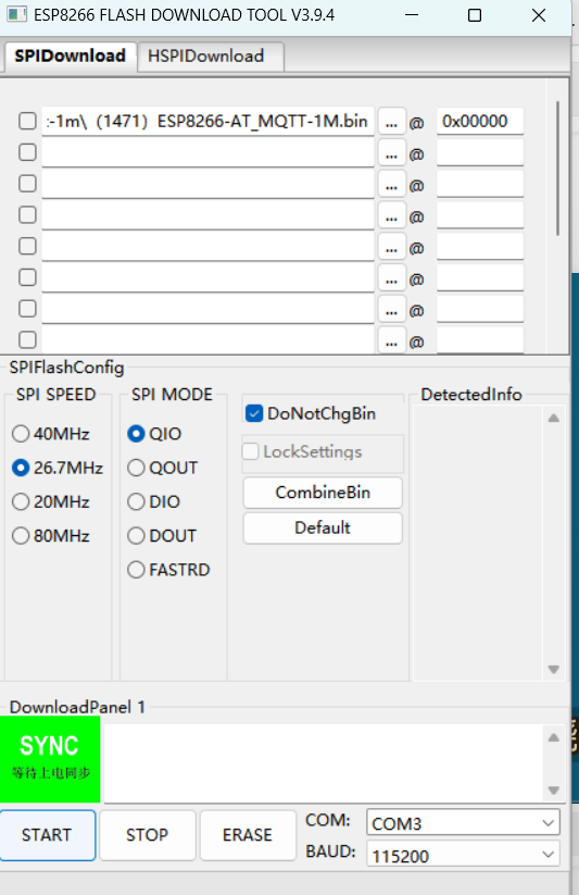
That “SYNC” message and the Chinese text “等待上电同步” literally mean the software is waiting for the ESP8266 to reboot into UART Download Mode.
The tool is essentially “listening” for a specific signal from the chip that says, “I’m ready to be flashed.” If it stays on this screen, the chip hasn’t sent that signal yet.
How to fix it
To get past this screen, you need to manually trigger the bootloader. Try these steps in order:
1. The “Two-Button” Reset (Most Common)
If your board has Flash and Reset buttons:
- Hold down the Flash (or Boot) button.
- Press and release the Reset (RST) button once.
- Release the Flash button.
The tool should immediately change from “SYNC” to “FINISH” or show a progress bar.
2. Check GPIO0 Wiring
If you are using a bare ESP-01 or ESP-12 chip (no buttons):
- GPIO0 must be connected to GND (Ground) when the chip powers on or resets.
- If GPIO0 is floating or connected to VCC, the chip will boot into “Flash Mode” (running your code) instead of “Download Mode” (receiving new code).
3. Power Supply Issues
The ESP8266 is notoriously “thirsty” for power during the sync phase.
- If you are powering it solely from a cheap USB-to-TTL adapter, it might not provide enough current (needs ~300mA+ peaks).
- Try using an external 3.3V power source (ensuring you share a common Ground with the USB adapter).
4. Verify the COM Port
Ensure COM3 is actually your ESP8266.
- Unplug the device; if COM3 disappears from your Device Manager, it’s the right one.
- If it stays, you’ve selected the wrong port.
Quick Settings Check
Looking at your screenshot, your addresses and files look okay for a 1MB (8Mbit) module, but keep these in mind:
- SPI MODE: If “QIO” fails, try “DIO”. Many ESP8266 modules (especially ESP-01) only support DIO.
- Baud Rate: 115200 is safe. If you have a high-quality cable, you can go faster (e.g., 921600), but stick to 115200 until you get a successful sync.