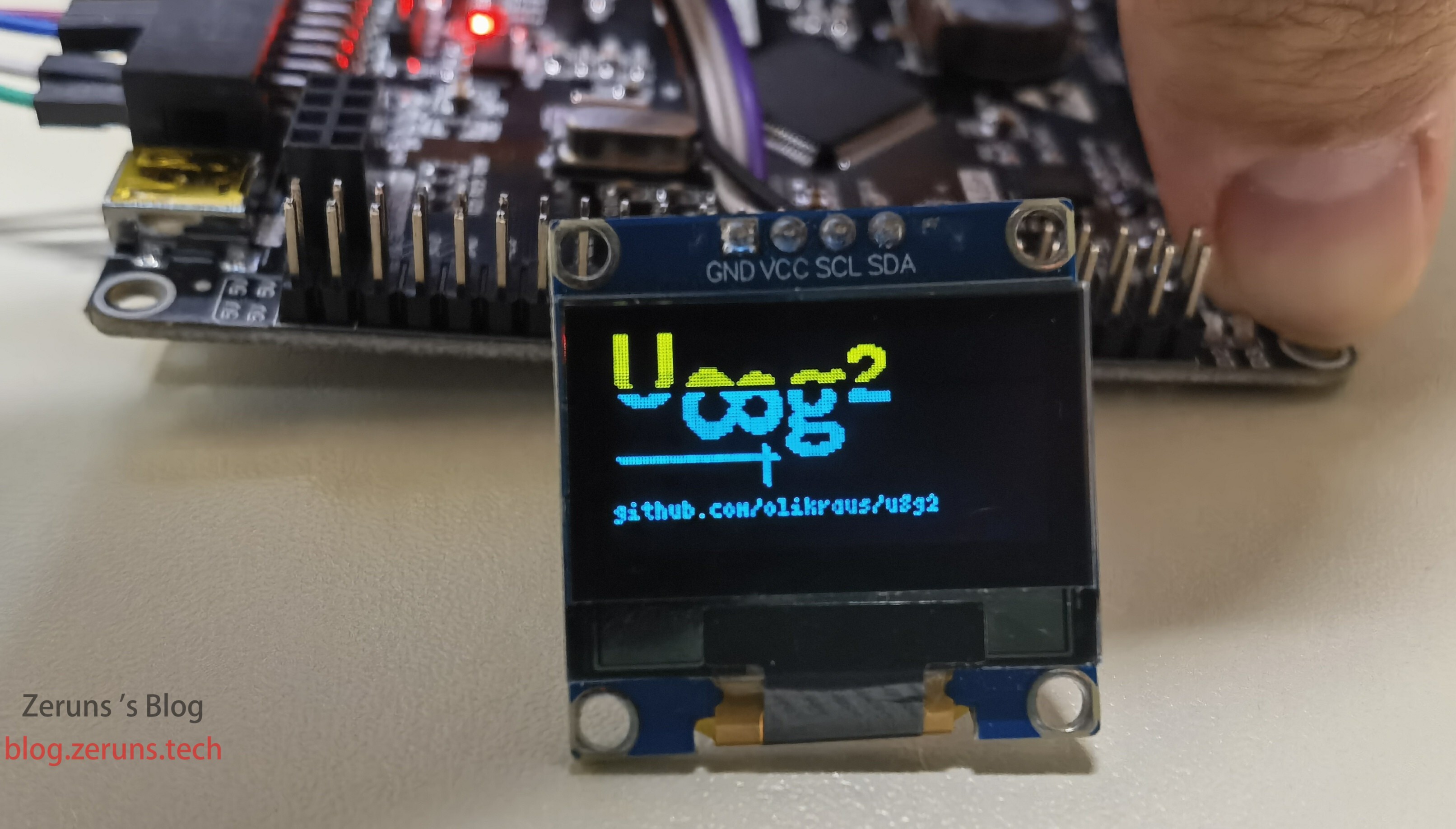
STM32F407 Standard Peripheral Library project template with the U8g2 graphics library ported, using a 0.96-inch OLED screen (SSD1306) driven by hardware IIC.
Spent a whole evening porting it. The development board’s main MCU is STM32F407VET6, I2C interface is I2C1, SCL connected to PB6, SDA connected to PB7.
Embedded-related articles: https://blog.zeruns.com/category/IOT/
Electronics/Circuit-related articles: https://blog.zeruns.com/category/electrical/
Electronics/MCU technical discussion group: 2169025065
U8g2 Introduction
U8g2 is a monochrome graphics library for embedded devices, supporting multiple monochrome OLED and LCD controllers such as SSD1306, ST7920, etc. The U8g2 library can be installed from the Arduino IDE library manager or ported to platforms like STM32. U8g2 supports three drawing modes: full-screen buffer mode, page buffer mode, and U8x8 character mode. Using U8g2 requires selecting the appropriate constructor, initializing the display, setting pin numbers, writing callback functions, and issuing drawing commands.
Advantages of U8g2 include support for multiple fonts, Chinese character display, and rich graphics primitives like lines, rectangles, circles, and bitmaps. Disadvantages are its memory footprint, slower speed, and lack of support for controller-less displays. Typical applications include sensor data display, clocks, menus, and animations. U8g2 is a powerful, well-compatible, and easy-to-use monochrome graphics library.
Effect Pictures


Demo video: https://www.bilibili.com/video/BV17W4y197WW/
About the Crystal Oscillator
I use an 8 MHz crystal; the PLL parameters in the clock-tree configuration have been modified so the MCU runs at 168 MHz. If you switch to a crystal of another frequency you must adjust the parameters—search online for how.
Places to modify:
stm32f4xx.h, line 137.
#define HSE_VALUE    ((uint32_t)8000000) /*!< Value of the External oscillator in Hz */
// Change 8000000 to your crystal frequency, in Hz
system_stm32f4xx.c, lines 364 and 394.
#if defined(STM32F40_41xxx) || defined(STM32F427_437xx) || defined(STM32F429_439xx) || defined(STM32F401xx) || defined(STM32F469_479xx)
 /* PLL_VCO = (HSE_VALUE or HSI_VALUE / PLL_M) * PLL_N */
 #define PLL_M      4
// The 4 here corresponds to /4 in the clock-tree diagram below
#if defined (STM32F40_41xxx)
#define PLL_N 168
// The 168 here corresponds to x168 in the clock-tree diagram below
```
## Component Purchase Links
- 0.96-inch OLED screen: [https://u.jd.com/1zjpDNC](https://union-click.jd.com/jdc?e=618%7Cpc%7C&p=JF8BARAJK1olXwQCXVheC0IUBV8IGloTXw4AU1hVDkweBV9MRANLAjZbERscSkAJHTdNTwcKBlMdBgABFksWAmkKE1kSWw4EU1dbFxJSXzI4WzB2K1NjPSw9VzFBQBpJTg5iPBhWElJROEonA24JGloSWgAAXG5tCEwnQgEIGV4SXwcFVW5cOEsQCmgNHV0UWg4EUVttD0seM20IGFgQWgQLUUJUDEoUAGY4K2sWbQECXUpbegpFF2l6K2sVbQUyVF9dAEgXA2cOGFMJXQMGXF9cFEsQCmgNHV0UXAEFVlttCkoWB2Y4K2tVGQViISotXEpUR2xIeSNWKGJREh4DXxF5AS1dSD0SFQNXVQoHfghLSm8LKw)
- STM32F407 development board: [https://s.click.taobao.com/7AtnHFu](https://s.click.taobao.com/t?e=m%3D2%26s%3DczQqv026Zjtw4vFB6t2Z2ueEDrYVVa64LKpWJ%2Bin0XLjf2vlNIV67lRwohxEizvIxa9spvDO8Cl%2FmzaS0s2vXCsmIF0UHtujBkxkgN7jKg%2BiJaQjFxYBevWfPAv4x3d%2FOlGkMkr%2BSUUYmUGuVZn0uRDBbf95h6seTxpmwkkouzqi1jMNxDhLMnotgd7NXRy%2F3OppJwt5ethtXyEYK9MgsI1cD97yFV3TmSpANgNSVXSPM7MeivsNdkAXdMlWzMNyHk3i9xXmKdKMJi1gYBJvNFSsXCNd9EoxE59iYTGkDbWFi4V5KBpmMoBZLSyIfgF7gR2l5BVRVVbGDmntuH4VtA%3D%3D&union_lens=lensId%3APUB%401686477136%40210562f5_0a55_188a9dee240_346f%4001%40eyJmbG9vcklkIjo2MTM1NCwiic3BtQiiI6Il9wb3J0YWxfdjJfcGFnZXNfcHJvbW9fZ29vZHNfaW5kZXhfaHRtIn0ie)
- Jumper wires: [https://u.jd.com/1zjFP0Z](https://union-click.jd.com/jdc?e=618%7Cpc%7C&p=JF8BAQcJK1olVQAKVlZZCUoXM2oJElkcXwUHXVtYOA9IWzFXKwJQGEdAX0BDUA5DX3BTTkRHA1ocUV9UCkIVAGoBHl4KBENeCW4NDA9CAGcLXjlHWnBqEycFACNOCxZoF1clXDYCVV9cCUwQBW0AK2sVWjZDOllYAE0XAF8JK1sSVAEHUldZCU4fBWo4HFscbQQCV11YD0keBnMBH1oWXg8yZG5eOEwXCnsOaRpHSQBwZG5dOEgnA24IE1gQXwYHV1lBCEkWAW8IB1sSVAEHUlhdAUweCmY4GVoUWQ8yZG4YXDFkd2tXEjhHCXxLB1wAXzsVAmxfRAN7X19ZVgg8VhZMYB94fChoFEVmZA)
## Code
Complete project download: [https://url.zeruns.com/JUoKJ](https://url.zeruns.com/JUoKJ) Extraction code: t6wt
Partial code:
**main.c**
```C
#include "stm32f4xx.h"
// #include "Timer.h"
#include "Delay.h"
#include "u8g2.h"
#include "OLED.h"
#include "IWDG.h"
uint8_t u8x8_gpio_and_delay(U8X8_UNUSED u8x8_t *u8x8, U8X8_UNUSED uint8_t msg, U8X8_UNUSED uint8_t arg_int, U8X8_UNUSED void *arg_ptr);
uint8_t u8x8_byte_hw_i2c(u8x8_t *u8x8, uint8_t msg, uint8_t arg_int, void *arg_ptr);
void u8g2_Init(u8g2_t *u8g2);
void draw(u8g2_t *u8g2);
int main(void)
{
uint8_t t = 0;
IWDG_Configuration(); // Initialize watchdog
OLED_I2C_Init(); // Initialize OLED
u8g2_t u8g2;
u8g2_Init(&u8g2); // Initialize U8g2
RCC_AHB1PeriphClockCmd(RCC_AHB1Periph_GPIOA, ENABLE); // Enable GPIOA peripheral clock
GPIO_InitTypeDef GPIO_InitStructure; // Define structure
GPIO_InitStructure.GPIO_Mode = GPIO_Mode_OUT; // Set GPIO mode to output
GPIO_InitStructure.GPIO_Pin = GPIO_Pin_6 | GPIO_Pin_7; // Set GPIO pins 6 and 7
GPIO_InitStructure.GPIO_Speed = GPIO_High_Speed; // Set GPIO speed to 100 MHz
GPIO_InitStructure.GPIO_OType = GPIO_OType_PP; // Set GPIO to push-pull output
GPIO_InitStructure.GPIO_PuPd = GPIO_PuPd_NOPULL; // Set GPIO pull-up/pull-down mode
GPIO_Init(GPIOA, &GPIO_InitStructure); // Initialize GPIO
Delay_ms(100);
u8g2_DrawLine(&u8g2, 0, 0, 127, 63); // Draw a line from (0,0) to (127,63)
u8g2_SendBuffer(&u8g2); // Send buffer data
u8g2_DrawLine(&u8g2, 127, 0, 0, 63);
u8g2_SendBuffer(&u8g2);
Delay_ms(300);
u8g2_ClearBuffer(&u8g2); // Clear buffer data
draw(&u8g2);
u8g2_SendBuffer(&u8g2);
Delay_ms(1000);
u8g2_ClearBuffer(&u8g2);
IWDG_FeedDog(); // Feed the dog to prevent CPU reset
u8g2_SetFont(&u8g2, u8g2_font_ncenB14_tr); // Select font
u8g2_DrawStr(&u8g2, 0, 15, "Hello World!");
u8g2_SetFont(&u8g2, u8g2_font_wqy16_t_chinese2);
u8g2_DrawUTF8(&u8g2, 0, 30, "H你好世界");
u8g2_SetFont(&u8g2, u8g2_font_wqy12_t_chinese2);
u8g2_DrawUTF8(&u8g2, 0, 43, "H你好世界");
u8g2_SetFont(&u8g2, u8g2_font_fur11_tr);
u8g2_DrawUTF8(&u8g2, 0, 59, "blog.zeruns.com");
u8g2_SendBuffer(&u8g2);
Delay_ms(1300);
while (1)
{
Delay_ms(100);
u8g2_ClearBuffer(&u8g2);// Clear buffer data
if (++t >= 32)
t = 1;
u8g2_DrawCircle(&u8g2, 64, 32, t, U8G2_DRAW_ALL); // Draw circle
u8g2_DrawCircle(&u8g2, 32, 32, t, U8G2_DRAW_ALL);
u8g2_DrawCircle(&u8g2, 96, 32, t, U8G2_DRAW_ALL);
u8g2_SendBuffer(&u8g2); // Send buffer data
GPIO_ToggleBits(GPIOA, GPIO_Pin_6);
IWDG_FeedDog(); // Feed the dog to prevent CPU reset
}
}
// https://blog.zeruns.com
uint8_t u8x8_byte_hw_i2c(u8x8_t *u8x8, uint8_t msg, uint8_t arg_int, void *arg_ptr)
{
static uint8_t buffer[32]; /* u8g2/u8x8 will never send more than 32 bytes between START_TRANSFER and END_TRANSFER */
static uint8_t buf_idx;
uint8_t *data;
switch (msg)
{
case U8X8_MSG_BYTE_SEND:
data = (uint8_t *)arg_ptr;
while (arg_int > 0)
{
buffer[buf_idx++] = *data;
data++;
arg_int--;
}
break;
case U8X8_MSG_BYTE_INIT:
/* add your custom code to init i2c subsystem */
break;
case U8X8_MSG_BYTE_START_TRANSFER:
buf_idx = 0;
break;
case U8X8_MSG_BYTE_END_TRANSFER:
HW_I2cWrite(buffer, buf_idx); // Hardware I2C write bytes
break;
default:
return 0;
}
return 1;
}
// https://blog.zeruns.com
uint8_t u8g2_gpio_and_delay(U8X8_UNUSED u8x8_t *u8x8, U8X8_UNUSED uint8_t msg, U8X8_UNUSED uint8_t arg_int, U8X8_UNUSED void *arg_ptr)
{
switch (msg)
{
case U8X8_MSG_GPIO_AND_DELAY_INIT:
OLED_I2C_Init(); // Initialize
break;
case U8X8_MSG_DELAY_MILLI:
Delay_ms(arg_int); // Delay
break;
case U8X8_MSG_GPIO_I2C_CLOCK:
break;
case U8X8_MSG_GPIO_I2C_DATA:
break;
default:
return 0;
}
return 1; // command processed successfully.
}
void u8g2_Init(u8g2_t *u8g2)
{
// u8g2_Setup_ssd1306_i2c_128x64_noname_f(u8g2, U8G2_R0, u8x8_byte_sw_i2c, u8x8_gpio_and_delay); // Initialize u8g2, software I2C
u8g2_Setup_ssd1306_i2c_128x64_noname_f(u8g2, U8G2_R0, u8x8_byte_hw_i2c, u8g2_gpio_and_delay); // Initialize u8g2, hardware I2C
u8g2_InitDisplay(u8g2); // Initialize according to selected chip, display remains off after init
u8g2_SetPowerSave(u8g2, 0); // Turn on display
u8g2_SetContrast(u8g2, 88); // Set screen brightness
u8g2_ClearBuffer(u8g2); // Clear buffer
}
// https://blog.vpszj.cn
void draw(u8g2_t *u8g2)
{
u8g2_SetFontMode(u8g2, 1); /* Font mode selection */
u8g2_SetFontDirection(u8g2, 0); /* Font direction selection */
u8g2_SetFont(u8g2, u8g2_font_inb24_mf); /* Font selection */
u8g2_DrawStr(u8g2, 0, 20, "U");
u8g2_SetFontDirection(u8g2, 1);
u8g2_SetFont(u8g2, u8g2_font_inb30_mn);
u8g2_DrawStr(u8g2, 21, 8, "8");
u8g2_SetFontDirection(u8g2, 0);
u8g2_SetFont(u8g2, u8g2_font_inb24_mf);
u8g2_DrawStr(u8g2, 51, 30, "g");
u8g2_DrawStr(u8g2, 67, 30, "\xb2");
u8g2_DrawHLine(u8g2, 2, 35, 47);
u8g2_DrawHLine(u8g2, 3, 36, 47);
u8g2_DrawVLine(u8g2, 45, 32, 12);
u8g2_DrawVLine(u8g2, 46, 33, 12);
u8g2_SetFont(u8g2, u8g2_font_4x6_tr);
u8g2_DrawStr(u8g2, 1, 54, "github.com/olikraus/u8g2");
}
```OLED.c
```C
#include "stm32f4xx.h"
#include "OLED_Font.h"
#include "Delay.h"
/*OLED screen address*/
#define OLED_ADDRESS 0x78
//I2C wait timeout
#define I2C_TIMEOUT 5000
/*Pin initialization*/
void OLED_I2C_Init(void)
{
RCC_APB1PeriphClockCmd(RCC_APB1Periph_I2C1,ENABLE); //Enable I2C1 clock
RCC_AHB1PeriphClockCmd(RCC_AHB1Periph_GPIOB,ENABLE);//Enable GPIOB clock
GPIO_PinAFConfig(GPIOB,GPIO_PinSource6,GPIO_AF_I2C1); //Enable PB6 alternate function connected to I2C1
GPIO_PinAFConfig(GPIOB,GPIO_PinSource7,GPIO_AF_I2C1);
/*STM32F407 hardware I2C: PB6 -- SCL; PB7 -- SDA */
GPIO_InitTypeDef GPIO_InitStructure; //Define structure to configure GPIO
GPIO_InitStructure.GPIO_Mode = GPIO_Mode_AF; //Set GPIO mode to alternate function
GPIO_InitStructure.GPIO_Speed = GPIO_High_Speed; //Set GPIO speed to 100MHz
GPIO_InitStructure.GPIO_OType = GPIO_OType_OD; //Set GPIO to open-drain output
GPIO_InitStructure.GPIO_PuPd = GPIO_PuPd_UP; //Set GPIO pull-up mode
GPIO_InitStructure.GPIO_Pin = GPIO_Pin_6 | GPIO_Pin_7; //Set GPIO pins
GPIO_Init(GPIOB, &GPIO_InitStructure);
I2C_DeInit(I2C1); //Reset I2C1 peripheral registers to default values
I2C_InitTypeDef I2C_InitStructure;
I2C_InitStructure.I2C_Mode = I2C_Mode_I2C; //Operating mode
I2C_InitStructure.I2C_DutyCycle = I2C_DutyCycle_2; //Clock duty cycle, Tlow/Thigh = 2
I2C_InitStructure.I2C_OwnAddress1 = 0x30; //Host I2C address, not used so can be arbitrary, no effect
I2C_InitStructure.I2C_Ack = I2C_Ack_Enable; //Enable acknowledge bit
I2C_InitStructure.I2C_AcknowledgedAddress = I2C_AcknowledgedAddress_7bit;//Set address length to 7 bits
I2C_InitStructure.I2C_ClockSpeed = 400000; //I2C transfer speed, 400K, check chip datasheet for supported speeds.
I2C_Init(I2C1, &I2C_InitStructure);
I2C_Cmd(I2C1, ENABLE);
}
// https://blog.zeruns.com
void HW_I2cWrite(uint8_t *buf,uint8_t len)
{
if(len<=0)
return ;
uint32_t wait_time=0;
/* wait for the busy flag to be reset */
while(I2C_GetFlagStatus(I2C1, I2C_FLAG_BUSY))
{
wait_time++;
if(wait_time>=I2C_TIMEOUT){
wait_time=0;
break;
}
}
I2C_GenerateSTART(I2C1, ENABLE);//Start I2C1
while(!I2C_CheckEvent(I2C1, I2C_EVENT_MASTER_MODE_SELECT))/*EV5, master mode*/
{
wait_time++;
if(wait_time>=I2C_TIMEOUT){
wait_time=0;
break;
}
}
I2C_Send7bitAddress(I2C1, OLED_ADDRESS, I2C_Direction_Transmitter); //Device address -- default 0x78
while(!I2C_CheckEvent(I2C1, I2C_EVENT_MASTER_TRANSMITTER_MODE_SELECTED))
{
wait_time++;
if(wait_time>=I2C_TIMEOUT){
wait_time=0;
break;
}
}
for(uint8_t i=0;i<len;i++)
{
I2C_SendData(I2C1, buf[i]);//Send data
while (!I2C_CheckEvent(I2C1, I2C_EVENT_MASTER_BYTE_TRANSMITTED))
{
wait_time++;
if(wait_time>=I2C_TIMEOUT){
wait_time=0;
break;
}
}
}
I2C_GenerateSTOP(I2C1, ENABLE);//Close I2C1 bus
}
Recommended Open-Source Projects
- Drew an MSP430F149 minimum system board and open-sourced it: https://blog.zeruns.com/archives/713.html
- STM32F030C8T6 minimum system board and LED chaser (schematic and PCB): https://blog.zeruns.com/archives/715.html
- SY8205 synchronous buck adjustable DC-DC power module (schematic and PCB): https://blog.zeruns.com/archives/717.html
- 2011 National Electronics Competition – Switching Power Module Parallel Power Supply System: https://blog.zeruns.com/archives/718.html
- 2007 Electronics Competition Power Topic: 30–36 V Adjustable Boost DC-DC Module (UC3843): https://oshwhub.com/zeruns/36v-sheng-ya-dcdc-mo-kuai-uc3842
Recommended Reading
- Cost-effective and Cheap VPS/Cloud Server Recommendations: https://blog.vpszj.cn/archives/41.html
- How to Build a Personal Blog: https://blog.zeruns.com/archives/218.html
- Minecraft Server Setup Tutorial: https://blog.zeruns.com/tag/mc/
- STM32 Reading SHT3x Series Temperature and Humidity Sensors: https://blog.zeruns.com/archives/700.html
- Using VSCode Instead of Keil for STM32 and 51 MCU Development: https://blog.zeruns.com/archives/690.html
-野草云 Hong Kong BGP Cloud Server Performance Review, 1C2G 100 Mbps Only 138 CNY/Year: https://blog.vpszj.cn/archives/1474.html - 雨云 Suqian 5900X High-Defense Cloud Server Performance Review, 2C4G 5 Mbps 150 G Defense Only 50 CNY/Month: https://blog.vpszj.cn/archives/1125.html