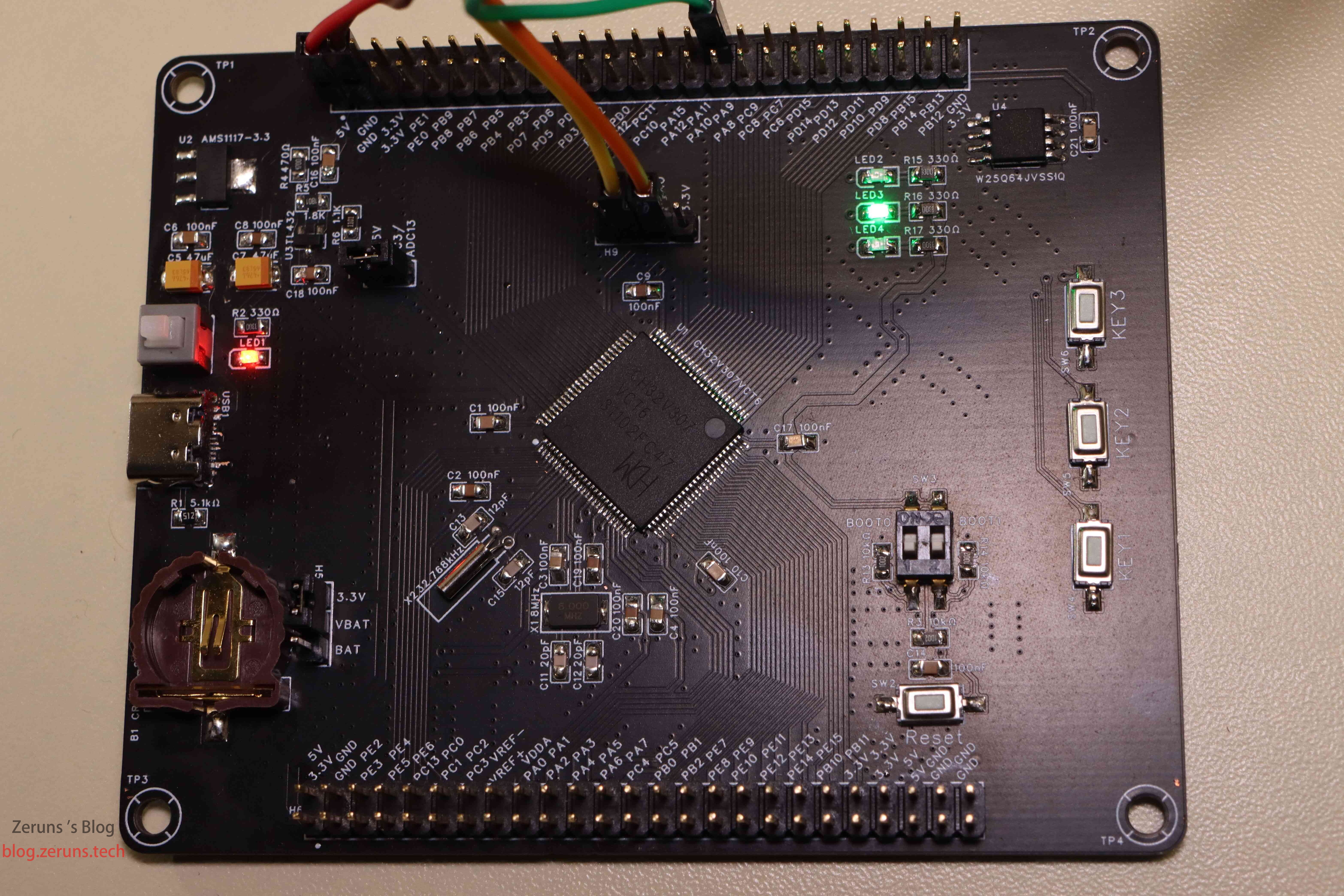
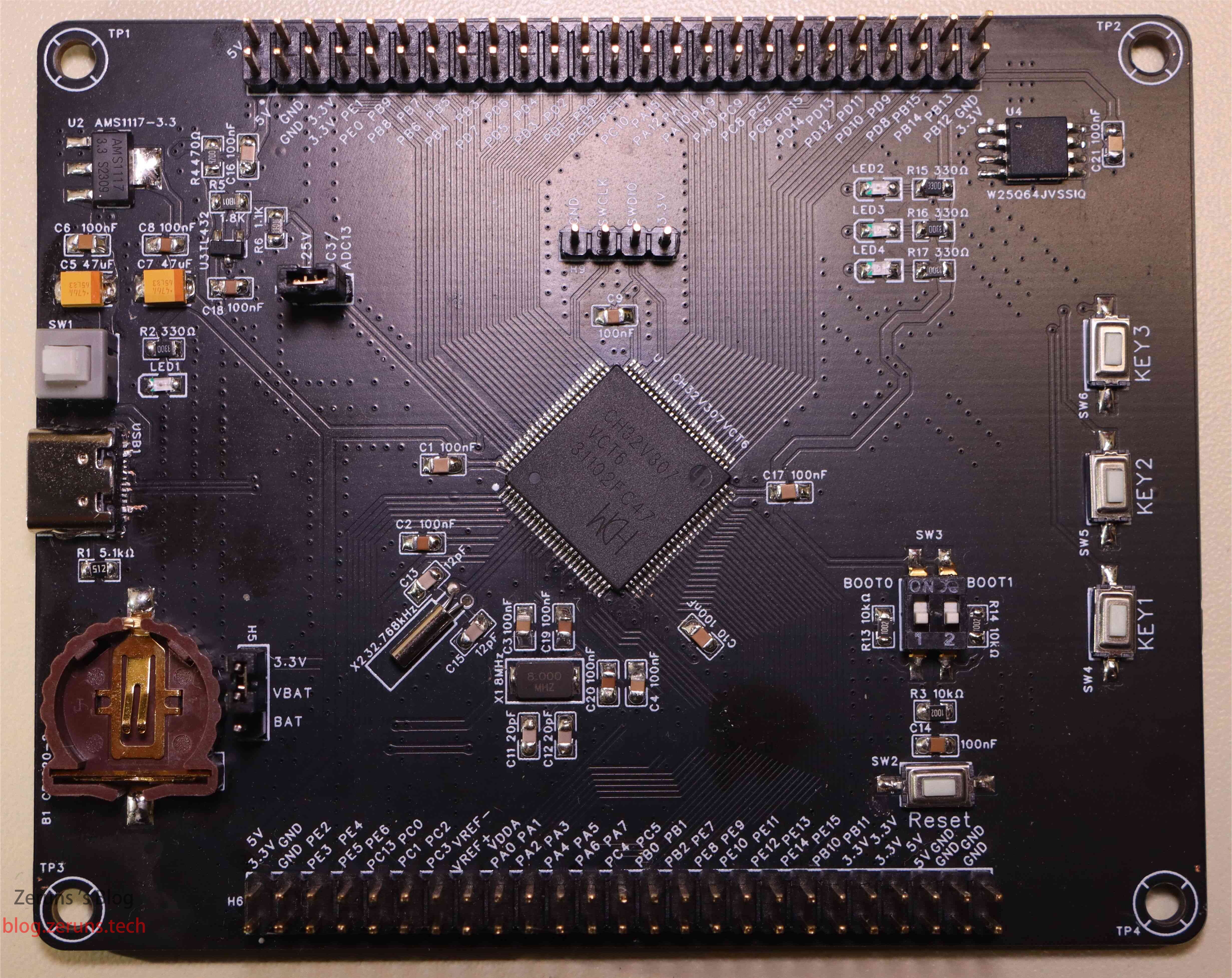
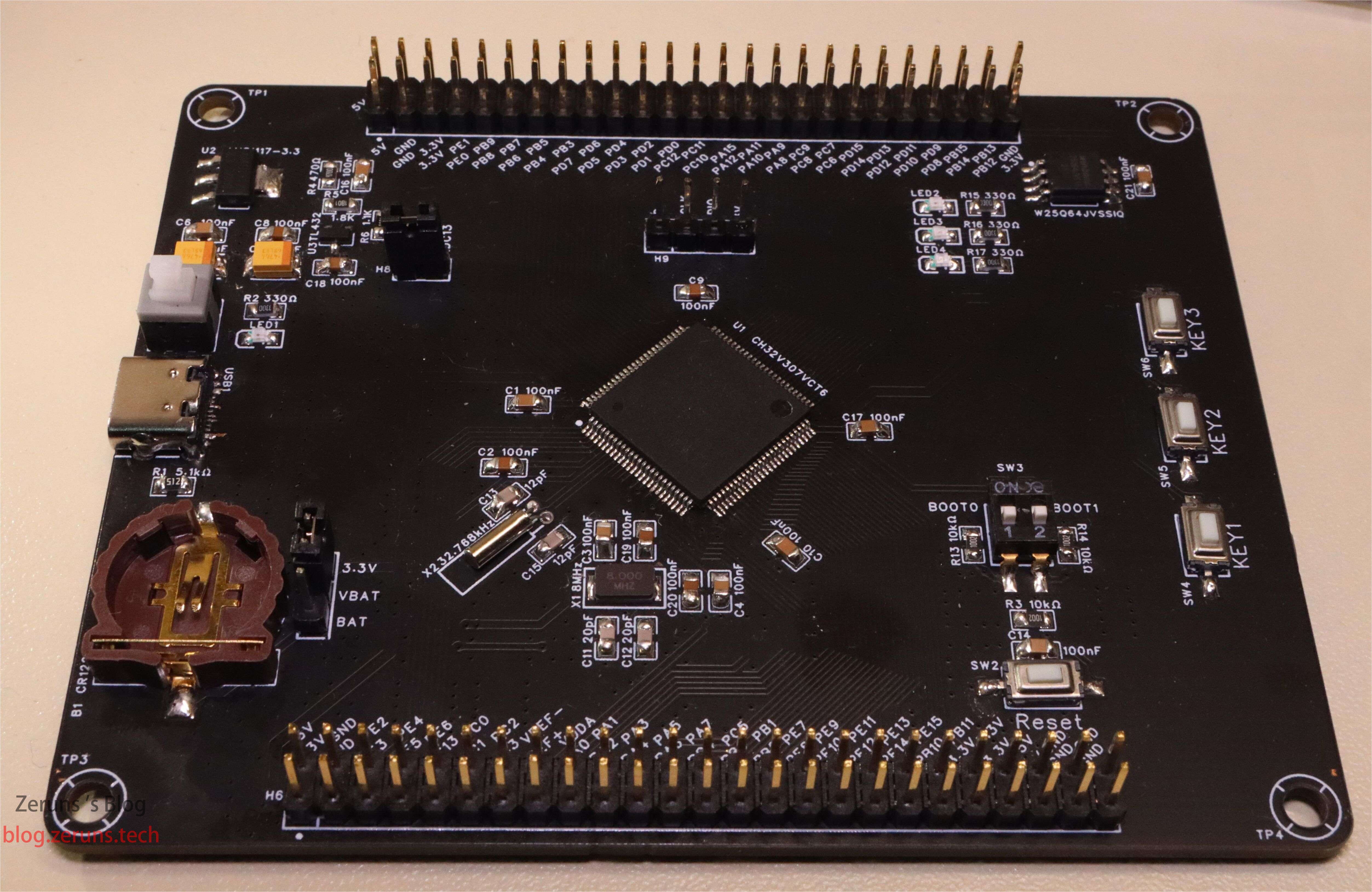
Qinheng CH32V307VCT6 Minimum System Board, breaks out all IO pins, one Type-C to USB2.0 full-speed OTG port, one Flash chip model W25Q64 64 Mbit connected to SPI2, on-board TL432 voltage reference 1.25 V (measured ≈1.246 V) can be jumpered to PC3/AD13, and 3.29 V reference can be routed to ADC VREF via 0 Ω resistor.
- Drew an MSP430F149 minimum-system board and open-sourced it: https://blog.zeruns.com/archives/713.html
- STM32F030C8T6 minimum-system board & running-light (schematic & PCB): https://blog.zeruns.com/archives/715.html
Electronics / MCU discussion group: 2169025065
CH32V307VCT6 Introduction
The CH32V series is an industrial-grade general-purpose MCU family built on the 32-bit QingKe RISC-V core. All chips add a hardware stack area and fast interrupt entry, greatly improving interrupt response versus the standard spec. CH32V303/305/307 adopt the V4F core with single-precision floating-point instructions for higher compute performance. Key features: 144 MHz zero-wait execution, up to 8 USART/UARTs, 4 motor timers, USB2.0 high-speed (480 Mbps) with built-in PHY, gigabit Ethernet MAC, etc.
Official product page: https://url.zeruns.com/Hcd8p
Free sample request (shipping collect): https://url.zeruns.com/x67TF
Datasheet download: https://url.zeruns.com/hDzqw 提取码:cn7c
Photos
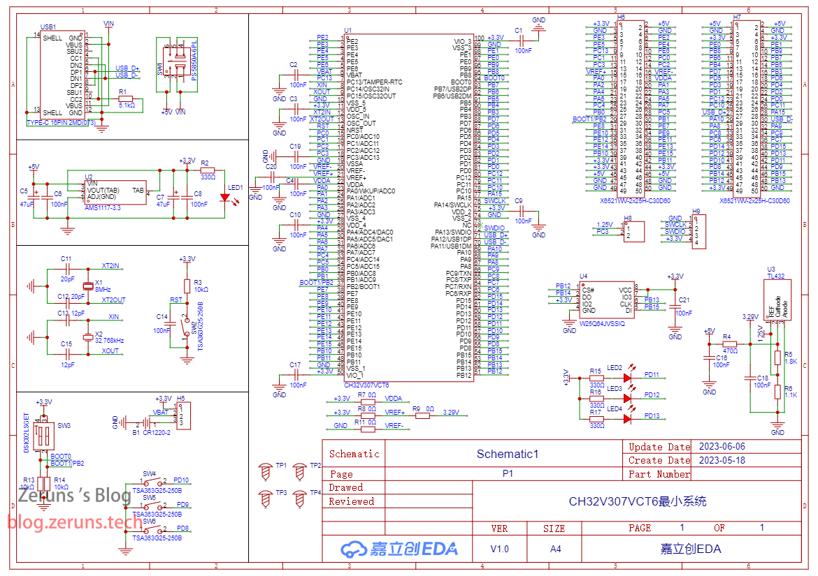
Schematic
The Type-C in the drawing has an issue: CC1 & CC2 must be separately pulled down with 5.1 kΩ; I tied them together so E-mark cables won’t power properly. Fixed on LCSC open-source project.
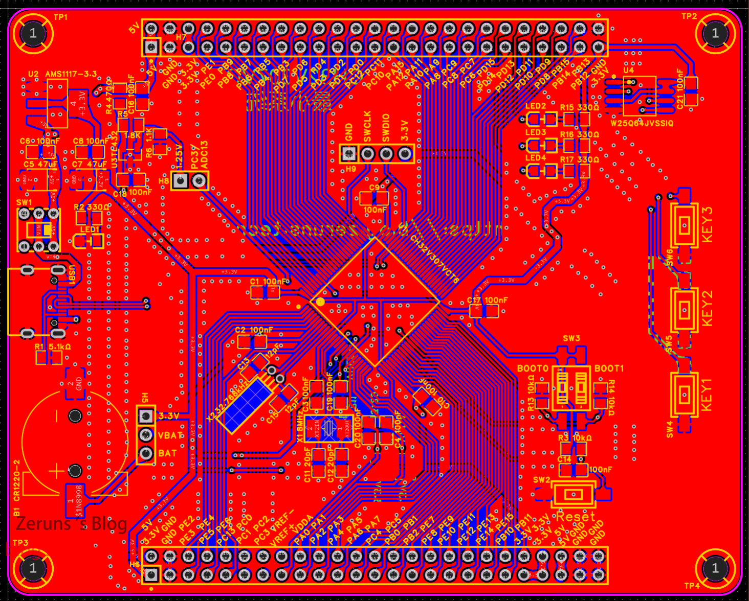
PCB
Top layer:
TL432 1.25 V (≈1.246 V) reference can be jumpered via H8 to GPIOPC3/ADC13.
SW3 sets BOOT0/1 strap pins (see datasheet §2.5.2); leave both low (off).
H9 header is for WCH-Link programming.
H5 header selects VBAT source: jumper to 3.3 V if no battery, or to BAT if installed.
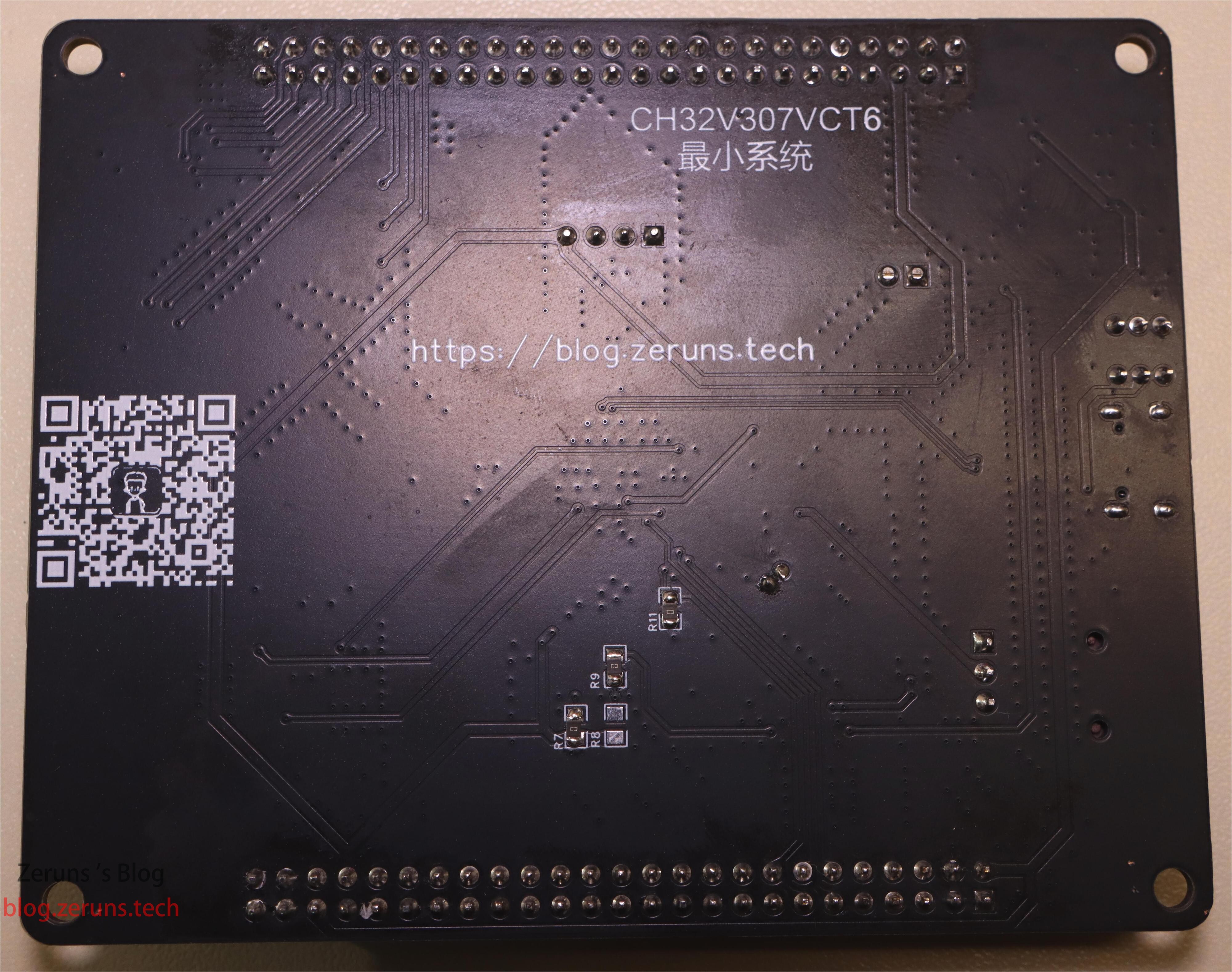
Bottom layer:
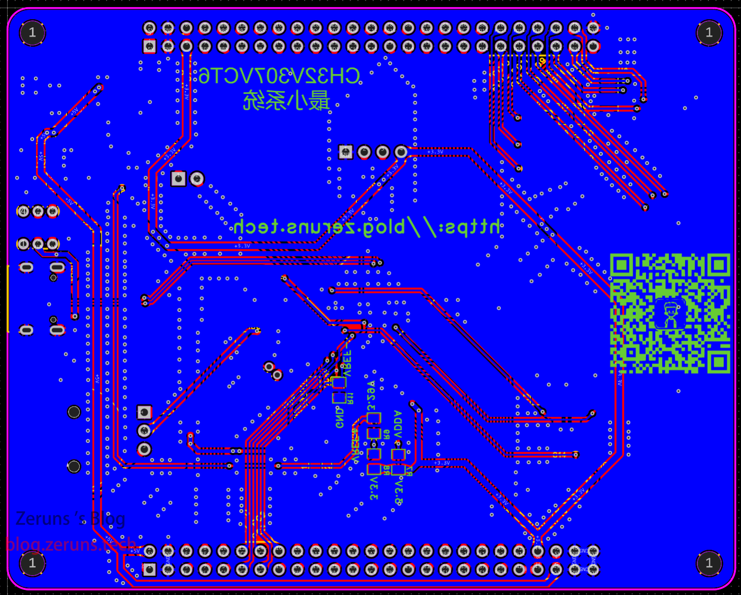
If external VDDA and VREF are not needed, solder 0 Ω resistors R11 & R7, then choose VREF+ source via R8/R9: LDO 3.3 V or TL432 3.29 V reference. Normally populate R9 only.
Component Purchase Links
- 0805 resistor sample book: https://u.jd.com/DzK9k0O
- 0805 capacitor sample book: https://s.click.taobao.com/cTZzzDu
- CH32V307VCT6: https://s.click.taobao.com/5SjzzDu
- W25Q64JV: https://s.click.taobao.com/YAv6NEu
- TL432: https://s.click.taobao.com/t3AzzDu
- WCH-Link: https://s.click.taobao.com/m6KyzDu
- Pin headers: https://u.jd.com/DbKUBDu
Recommended component store: LCSC. Register with discount: https://activity.szlcsc.com/invite/D03E5B9CEAAE70A4.html
All parts are available at LCSC; click “Order at LCSC” in the open-source BOM to one-click import them into your cart.
Demo Code
Full project download: https://url.zeruns.com/2q4tX 提取码:9527
Open-source project page: https://url.zeruns.com/Avda8
The demo uses Harmony LiteOS-M and creates three tasks: LED2 toggles every 500 ms, LED3 every 1 s, LED4 every 2 s. (The GIF above is 1.5× speed.)
Open the project with MounRiver Studio.
main.c:
/*
 * Copyright (c) 2013-2019 Huawei Technologies Co., Ltd. All rights reserved.
 * Copyright (c) 2020-2021 Huawei Device Co., Ltd. All rights reserved.
 *
 * Redistribution and use in source and binary forms, with or without modification,
 * are permitted provided that the following conditions are met:
 *
 * 1. Redistributions of source code must retain the above copyright notice, this list of
 *    conditions and the following disclaimer.
 *
 * 2. Redistributions in binary form must reproduce the above copyright notice, this list
 *    of conditions and the following disclaimer in the documentation and/or other materials
 *    provided with the distribution.
 *
 * 3. Neither the name of the copyright holder nor the names of its contributors may be used
 *    to endorse or promote products derived from this software without specific prior written
 *    permission.
 *
 * THIS SOFTWARE IS PROVIDED BY THE COPYRIGHT HOLDERS AND CONTRIBUTORS
 * "AS IS" AND ANY EXPRESS OR IMPLIED WARRANTIES, INCLUDING, BUT NOT LIMITED TO,
 * THE IMPLIED WARRANTIES OF MERCHANTABILITY AND FITNESS FOR A PARTICULAR
 * PURPOSE ARE DISCLAIMED. IN NO EVENT SHALL THE COPYRIGHT HOLDER OR
 * CONTRIBUTORS BE LIABLE FOR ANY DIRECT, INDIRECT, INCIDENTAL, SPECIAL,
 * EXEMPLARY, OR CONSEQUENTIAL DAMAGES (INCLUDING, BUT NOT LIMITED TO,
 * PROCUREMENT OF SUBSTITUTE GOODS OR SERVICES; LOSS OF USE, DATA, OR PROFITS;
 * OR BUSINESS INTERRUPTION) HOWEVER CAUSED AND ON ANY THEORY OF LIABILITY,
 * WHETHER IN CONTRACT, STRICT LIABILITY, OR TORT (INCLUDING NEGLIGENCE OR
 * OTHERWISE) ARISING IN ANY WAY OUT OF THE USE OF THIS SOFTWARE, EVEN IF
 * ADVISED OF THE POSSIBILITY OF SUCH DAMAGE.
 */

#include "debug.h"
#include "los_tick.h"
#include "los_task.h"
#include "los_config.h"
#include "los_interrupt.h"
#include "los_debug.h"
#include "los_compiler.h"

/* Global define */
``````c
/* Global Variable */
__attribute__((aligned (8))) UINT8 g_memStart[LOSCFG_SYS_HEAP_SIZE];
UINT32 g_VlaueSp=0;

u8 i = 0,j=0,k=0;

/*********************************************************************
 * @fn      taskSampleEntry3
 *
 * @brief   taskSampleEntry3 program.
 *
 * @return  none
 */
VOID taskSampleEntry3(VOID)
{
    while(1) {
      LOS_TaskDelay(2000);
      printf("taskSampleEntry3 running,task3 SP:%08x\n",__get_SP());
      GPIO_WriteBit(GPIOD, GPIO_Pin_13, (k == 0) ? (k = Bit_SET) : (k = Bit_RESET));
    }
}

/*********************************************************************
 * @fn      taskSampleEntry2
 *
 * @brief   taskSampleEntry2 program.
 *
 * @return  none
 */
VOID taskSampleEntry2(VOID)
{
    while(1) {
      LOS_TaskDelay(1000);
      printf("taskSampleEntry2 running,task2 SP:%08x\n",__get_SP());
      GPIO_WriteBit(GPIOD, GPIO_Pin_12, (j == 0) ? (j = Bit_SET) : (j = Bit_RESET));
    }
}

/*********************************************************************
 * @fn      taskSampleEntry1
 *
 * @brief   taskSampleEntry1 program.
 *
 * @return  none
 */
VOID taskSampleEntry1(VOID)
{
    while(1) {
      LOS_TaskDelay(500);
      printf("taskSampleEntry1 running,task1 SP:%08x\n",__get_SP());
      GPIO_WriteBit(GPIOD, GPIO_Pin_11, (i == 0) ? (i = Bit_SET) : (i = Bit_RESET));
    }

}
// https://blog.zeruns.com
/*********************************************************************
 * @fn      EXTI0_INT_INIT
 *
 * @brief   Initializes EXTI0 collection.
 *
 * @return  none
 */
void EXTI0_INT_INIT(void)
{
  GPIO_InitTypeDef  GPIO_InitStructure={0};
  EXTI_InitTypeDef EXTI_InitStructure={0};
  NVIC_InitTypeDef NVIC_InitStructure={0};

  RCC_APB2PeriphClockCmd(RCC_APB2Periph_AFIO|RCC_APB2Periph_GPIOA,ENABLE);

  GPIO_InitStructure.GPIO_Pin = GPIO_Pin_0;
  GPIO_InitStructure.GPIO_Mode = GPIO_Mode_IPU;
  GPIO_Init(GPIOA, &GPIO_InitStructure);

   /* GPIOA ----> EXTI_Line0 */
  GPIO_EXTILineConfig(GPIO_PortSourceGPIOA,GPIO_PinSource0);
  EXTI_InitStructure.EXTI_Line=EXTI_Line0;
  EXTI_InitStructure.EXTI_Mode = EXTI_Mode_Interrupt;
  EXTI_InitStructure.EXTI_Trigger = EXTI_Trigger_Falling;
  EXTI_InitStructure.EXTI_LineCmd = ENABLE;
  EXTI_Init(&EXTI_InitStructure);

  NVIC_InitStructure.NVIC_IRQChannel = EXTI0_IRQn;
  NVIC_InitStructure.NVIC_IRQChannelPreemptionPriority = 0;
  NVIC_InitStructure.NVIC_IRQChannelSubPriority = 4;
  NVIC_InitStructure.NVIC_IRQChannelCmd = ENABLE;
  NVIC_Init(&NVIC_InitStructure);
}

void GPIO_INIT(void) {
    GPIO_InitTypeDef GPIO_InitStructure = { 0 };

    RCC_APB2PeriphClockCmd(RCC_APB2Periph_GPIOD, ENABLE);
    GPIO_InitStructure.GPIO_Pin = GPIO_Pin_12|GPIO_Pin_11|GPIO_Pin_13;
    GPIO_InitStructure.GPIO_Mode = GPIO_Mode_Out_PP;
    GPIO_InitStructure.GPIO_Speed = GPIO_Speed_50MHz;
    GPIO_Init(GPIOD, &GPIO_InitStructure);

}

/*********************************************************************
 * @fn      taskSample
 *
 * @brief   taskSample program.
 *
 * @return  none
 */
UINT32 taskSample(VOID) {
    UINT32 uwRet;
    UINT32 taskID1, taskID2, taskID3;
    TSK_INIT_PARAM_S stTask = { 0 };
    stTask.pfnTaskEntry = (TSK_ENTRY_FUNC) taskSampleEntry1;
    stTask.uwStackSize = 0X500;
    stTask.pcName = "taskSampleEntry1";
    stTask.usTaskPrio = 6;/* High priority */
    uwRet = LOS_TaskCreate(&taskID1, &stTask);
    if (uwRet != LOS_OK) {
        printf("create task1 failed\n");
    }

    stTask.pfnTaskEntry = (TSK_ENTRY_FUNC) taskSampleEntry2;
    stTask.uwStackSize = 0X500;
    stTask.pcName = "taskSampleEntry2";
    stTask.usTaskPrio = 7;/* Low priority */
    uwRet = LOS_TaskCreate(&taskID2, &stTask);
    if (uwRet != LOS_OK) {
        printf("create task2 failed\n");
    }

    stTask.pfnTaskEntry = (TSK_ENTRY_FUNC) taskSampleEntry3;
        stTask.uwStackSize = 0X500;
        stTask.pcName = "taskSampleEntry3";
        stTask.usTaskPrio = 7;/* Low priority */
        uwRet = LOS_TaskCreate(&taskID3, &stTask);
        if (uwRet != LOS_OK) {
            printf("create task3 failed\n");
        }
// https://blog.vpszj.cn
    EXTI0_INT_INIT();
    return LOS_OK;
}

/*********************************************************************
 * @fn      main
 *
 * @brief   Main program.
 *
 * @return  none
 */
LITE_OS_SEC_TEXT_INIT int main(void)
{
    unsigned int ret;

	NVIC_PriorityGroupConfig(NVIC_PriorityGroup_0);
    SystemCoreClockUpdate();
    Delay_Init();
    GPIO_INIT();
	USART_Printf_Init(115200);

	printf("SystemClk:%d\r\n",SystemCoreClock);
	printf( "ChipID:%08x\r\n", DBGMCU_GetCHIPID() );

    ret = LOS_KernelInit();
    taskSample();
    if (ret == LOS_OK)
    {
        LOS_Start();
    }

    GPIO_WriteBit(GPIOC, GPIO_Pin_1,RESET);

    while (1) {
        __asm volatile("nop");
    }

}


/*********************************************************************
 * @fn      EXTI0_IRQHandler
 *
 * @brief   This function handles EXTI0 Handler.
 *
 * @return  none
 */
void EXTI0_IRQHandler(void) __attribute__((interrupt("WCH-Interrupt-fast")));
void EXTI0_IRQHandler(void)
{
  /* The interrupt stack uses the value originally set by main. Separating the interrupt stack and thread stack ensures that when a thread enters an interrupt,
   * and if the interrupt function has deep nesting, the thread stack won't overflow. However, with the current approach, when a thread enters an interrupt,
   * the 16 caller registers saved by the compiler are still pushed onto the thread stack. If you want the caller registers to be pushed onto the interrupt stack,
   * the entry and exit of the interrupt function need to be written in assembly, and the user's interrupt handler can be called in between.
   * See the ipq_entry example in los_exc.S */
  GET_INT_SP();
  HalIntEnter();
  if(EXTI_GetITStatus(EXTI_Line0)!=RESET)
  {
    g_VlaueSp= __get_SP();
    printf("Run at EXTI:");
    printf("interruption sp:%08x\r\n",g_VlaueSp);
    HalDisplayTaskInfo();
    EXTI_ClearITPendingBit(EXTI_Line0);     /* Clear Flag */
  }
  HalIntExit();
  FREE_INT_SP();
}
Recommended Open-Source Projects
- SY8205 Synchronous Buck Adjustable DC-DC Power Module (Schematic and PCB): https://blog.zeruns.com/archives/717.html
- 2011 National Electric Design Contest – Switching Power Supply Module Parallel Power Supply System: https://blog.zeruns.com/archives/718.html
- 2007 Electric Design Contest Power Problem: 30 to 36V Adjustable Boost DC-DC Module (UC3843): https://oshwhub.com/zeruns/36v-sheng-ya-dcdc-mo-kuai-uc3842
- STC12C5A60S2 Minimum System Board / 51 Microcontroller Temperature Display and Temperature-Controlled Fan: https://blog.zeruns.com/archives/721.html
- STM32F407 Standard Library Project Template with U8g2 Graphics Library Ported: https://blog.zeruns.com/archives/722.html
Recommended Reading
- Cost-Effective and Cheap VPS/Cloud Server Recommendations: https://blog.vpszj.cn/archives/41.html
- How to Build a Personal Blog: https://blog.zeruns.com/archives/218.html
- Minecraft Server Setup Tutorial: https://blog.zeruns.com/tag/mc/
- STM32 Reading SHT3x Series Temperature and Humidity Sensors: https://blog.zeruns.com/archives/700.html
- Using VSCode Instead of Keil for STM32 and 51 Microcontroller Development: https://blog.zeruns.com/archives/690.html
- RainYun US High-Defense Dedicated Server Performance Review, 8C16G 50M 200G Defense: https://blog.vpszj.cn/archives/1603.html
- TeYuYun Hubei Shiyan High-Defense VPS Performance Review, 4C8G 10M 100G Defense: https://blog.vpszj.cn/archives/1523.html