STC12C5A60S2 Minimum System Board / 51 MCU Temperature Display and Temperature-Controlled Fan, onboard DS18B20 and TM1650 + 4-digit 7-segment LED.
Electronics / MCU Technical Exchange Group: 2169025065
Project Introduction
Microcontroller course project: build an intelligent temperature-controlled fan that starts when the temperature reaches the set lower limit, outputs a proportional PWM duty cycle to control the fan speed when the temperature is between the lower and upper limits, and runs the fan at full speed when the temperature exceeds the upper limit.
Uses STC12C5A60S2 MCU, DS18B20 temperature sensor, and TM1650 chip to drive the 7-segment display via I2C.
This open-source project can also be used directly as an STC12C5A60S2 minimum system; all I/O pins are broken out.
STC12C5A60S2 Introduction
The STC12C5A60S2 series is a single-clock/machine-cycle (1T) MCU produced by STC. It is a high-speed, low-power, ultra-interference-resistant next-generation 8051 microcontroller, fully instruction-compatible with traditional 8051 but 8–12× faster. It integrates an internal MAX810 dedicated reset circuit, 2 PWM channels, 8-channel high-speed 10-bit ADC (250 kS/s), ideal for motor control and high-interference environments.
TM1650
TM1650 is a dedicated LED (7-segment display) driver with keypad-scan interface. It integrates MCU digital I/O control, data latches, LED drivers, key scanning, and brightness adjustment. TM1650 is stable, reliable, and highly interference-resistant, suitable for 24-hour continuous operation.
- Two display modes: 8-segment × 4-digit and 7-segment × 4-digit
- Supports single keys 7×4 bit (28 keys) and combo keys (4 keys)
- 8-level brightness adjustment
- Segment drive current >25 mA, digit drive current >150 mA
- High-speed 2-wire serial interface (CLK, DAT)
- Built-in RC oscillator
- Built-in power-on reset circuit
- Built-in data latch circuit
- 3–5.5 V supply voltage
- Strong anti-interference ability
- Available in DIP16 and SOP16 packages
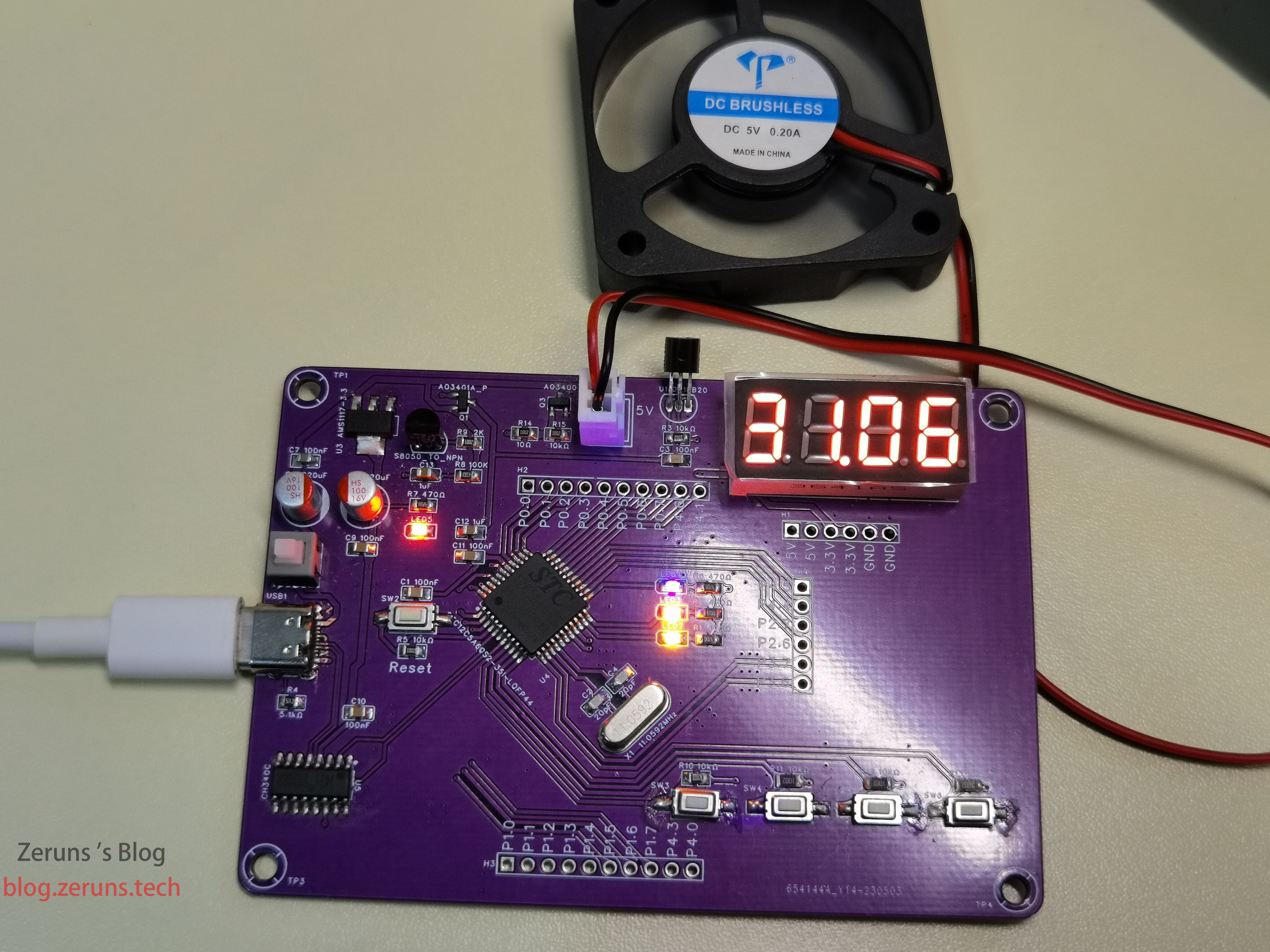
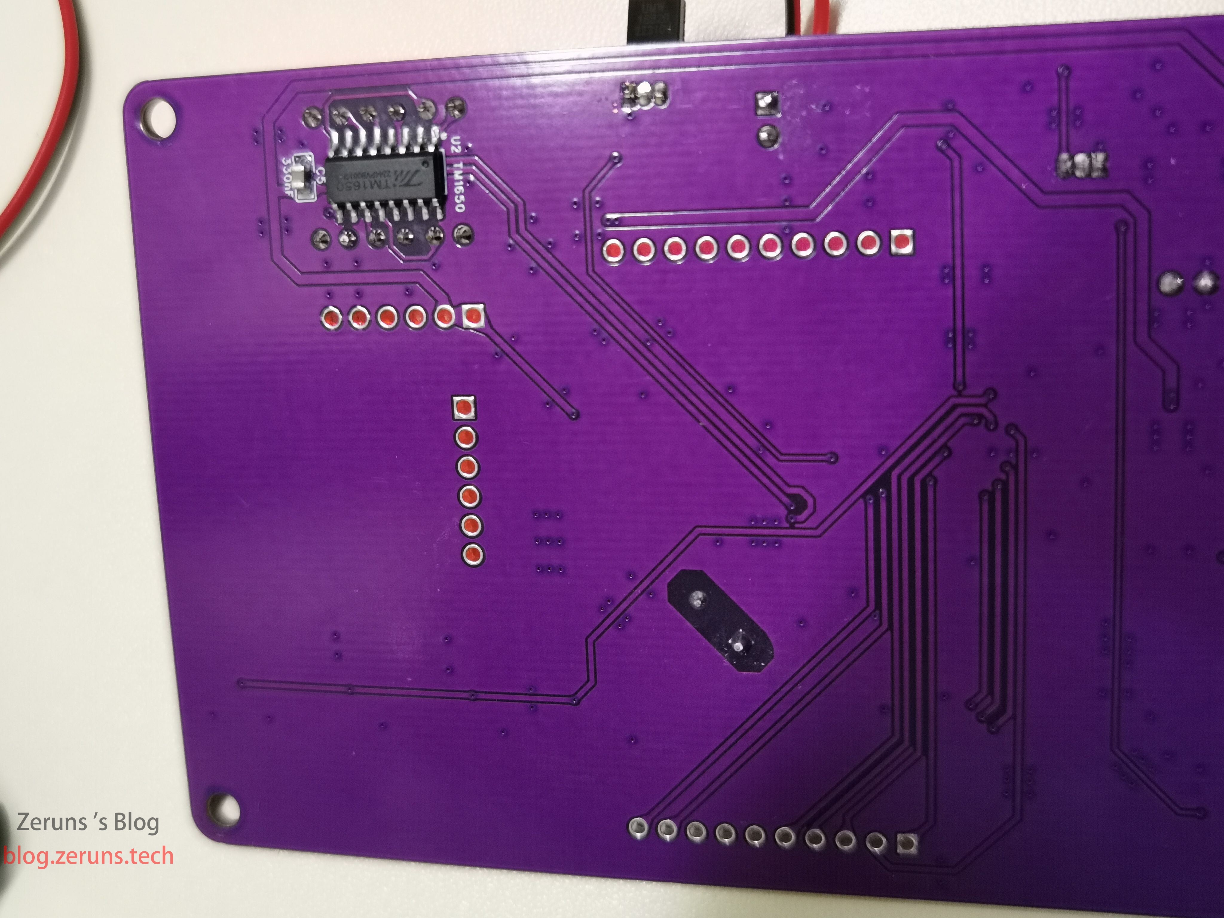
Physical Photos
Schematic

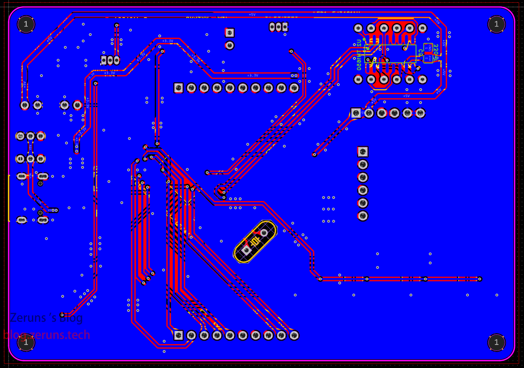
PCB
Top layer:

Bottom layer:
Component Purchase Links
- 0805 Resistor Sample Book: https://s.click.taobao.com/oWjIgGu
- 0805 Capacitor Sample Book: https://s.click.taobao.com/r9ea1Hu
- Common-Cathode 7-Segment Display: https://u.jd.com/1ir7YWC
- TM1650 Chip: https://s.click.taobao.com/pYveTFu
- DS18B20 Chip: https://s.click.taobao.com/zaNQqFu
Recommended component store: LCSC. Register with discount link: https://activity.szlcsc.com/invite/D03E5B9CEAAE70A4.html
Code & Documentation
Full project and datasheets download: https://url.zeruns.com/AkHGU Extraction code: 6gzf
LCSC Open-Source Project Link: https://url.zeruns.com/46y43
main.c
#include <STC12C5A60S2.H>
#include<intrins.h>
#include "TM1650.h"
#include "DS18B20.h"
#include "Key.h"

sbit LED2 = P2 ^ 3;
sbit LED3 = P2 ^ 4;
sbit LED4 = P2 ^ 5;
sbit FAN = P4 ^ 2;

// Define TM1650 display array
unsigned char code dig1[11] = {0x3f, 0x06, 0x5b, 0x4f, 0x66, 0x6d, 0x7d, 0x07, 0x7f, 0x6f, 0x40}; // 0,1,2,3,4,5,6,7,8,9,- // no decimal point
unsigned char code dig2[11] = {0xbf, 0x86, 0xdb, 0xcf, 0xe6, 0xed, 0xfd, 0x87, 0xff, 0xef, 0x40}; // 0,1,2,3,4,5,6,7,8,9,- // with decimal point
unsigned char code dig3[3] = {0x76, 0x38, 0x40};                                                  // H, L, -

// Define counter variables
unsigned int count = 0, count1 = 0; // counter values

// Temperature upper and lower limits
uint8_t H_Set = 50;
uint8_t L_Set = 25;

// Define display mode enumeration
typedef enum
{
    H_mode = 0, // upper limit temperature setting
    L_mode,     // lower limit temperature setting
    T_mode,     // temperature display
} Display_MODE;

Display_MODE Display_mode = T_mode;

uint16_t temp;

// Timer/counter initialization
void Timer_Init()
{
    EA = 1;       // enable global interrupt
    AUXR |= 0x80; // timer0 1T mode
    TMOD &= 0xF0; // clear low 4 bits, set 16-bit counter mode
    TMOD |= 0x01; // set high 4 bits to timer mode 0
    TL0 = 0xCD;   // set timer initial value
    TH0 = 0xD4;   // set timer initial value
    TF0 = 0;      // clear TF0 flag
    TR0 = 1;      // timer0 start
    ET0 = 1;      // enable timer0 interrupt

    AUXR &= 0xBF; // timer1 12T mode
    TMOD &= 0x0F; // set timer mode
    TMOD |= 0x10; // set timer mode
    TL1 = 0x00;   // set timer initial value
    TH1 = 0xB8;   // set timer initial value
    TF1 = 0;      // clear TF1 flag
    TR1 = 1;      // timer1 start
    ET1 = 1;      // enable timer1 interrupt
}

// Timer/counter 0 interrupt service routine
void Timer0_Isr(void) interrupt 1
{
    TL0 = 0xCD; // set timer initial value
    TH0 = 0xD4; // set timer initial value
    count++;    // increment every 1 ms
    count1++;
}

void Timer1_Isr(void) interrupt 3
{
    TL1 = 0x00; // set timer initial value
    TH1 = 0xB8; // set timer initial value
    key_status_check(0, KEY1);
    key_status_check(1, KEY2);
    key_status_check(2, KEY3);
    key_status_check(3, KEY4);
}

void PWMInit()
{
    // Configure PWM
    CCON = 0; // Initial PCA control register
              // PCA timer stop running
              // Clear CF flag
              // Clear all module interrupt flag
    CL = 0;   // Reset PCA base timer
    CH = 0;
    CMOD = 0x00;            // Set PCA timer clock to crystal/12, disable PCA overflow interrupt
    CCAP0H = CCAP0L = 0x80; // PWM0 port output 50% duty cycle square wave
    CCAPM0 = 0x42;          // Enable comparator, enable PWM0
    AUXR1 |= 0x40;          // Switch PWM output IO to P4

    CR = 1; // PCA timer start run
}
// https://blog.zeruns.com
void SetPwmDutyCycle(unsigned char dutyCycle)
{
    // dutyCycle range 0-100, representing 0% to 100% duty cycle.
    unsigned char newValue = ((100 - dutyCycle) * 255) / 100;
    CCAP0H = CCAP0L = newValue; // Update CCAP0L to change PWM duty cycle
}

// Main function
void main()
{
    TM_WrCmd(0x21); // Set TM1650 to 8-segment×4-digit mode, turn on display, brightness level 2
    Timer_Init();   // initialize timer
    Key_Init();     // initialize key state machine
    P4M0 = 0x04;    // set P4.2 as push-pull output
    P4M1 = 0x00;
    PWMInit();          // initialize PWM
    SetPwmDutyCycle(0); // set PWM duty cycle to 0
    temp = GetTemp();
// https://blog.zeruns.com
    while (1) // infinite loop
    {
        if (count >= 100) // every 100 ms
        {
            count = 0;
            temp = GetTemp();           // read temperature
            if (Display_mode == T_mode) // temperature display mode
            {
                TM_WrDat(0x68, dig1[temp / 1000]);     // write digit 1 data
                TM_WrDat(0x6a, dig2[temp / 100 % 10]); // write digit 2 data
                TM_WrDat(0x6c, dig1[temp / 10 % 10]);  // write digit 3 data
                TM_WrDat(0x6e, dig1[temp % 10]);       // write digit 4 data
            }
            if (Display_mode == H_mode) // upper limit setting
            {
                TM_WrDat(0x68, dig3[0]);          // digit 1 show H
                TM_WrDat(0x6a, dig3[2]);          // digit 2 show -
                TM_WrDat(0x6c, dig1[H_Set / 10]); // write digit 3 data
                TM_WrDat(0x6e, dig1[H_Set % 10]); // write digit 4 data
            }
            else if (Display_mode == L_mode) // lower limit setting
            {
                TM_WrDat(0x68, dig3[1]);          // digit 1 show L
                TM_WrDat(0x6a, dig3[2]);          // digit 2 show -
                TM_WrDat(0x6c, dig1[L_Set / 10]); // write digit 3 data
                TM_WrDat(0x6e, dig1[L_Set % 10]); // write digit 4 data
            }

            if (temp / 100 >= L_Set && temp / 100 < H_Set) // when temperature between lower and upper limits, set fan PWM duty cycle accordingly
            {
                uint8_t pwm_set = (uint8_t)((temp / 100.0 - (float)L_Set) / ((H_Set - L_Set) / 55.0) + 45.0 + 0.5);
                SetPwmDutyCycle(pwm_set);
            }
            else if (temp / 100 >= H_Set) // when temperature above upper limit, fan full speed
            {
                SetPwmDutyCycle(100); // set duty cycle 100%
            }
            else if (temp / 100 < L_Set) // when temperature below lower limit, fan off
            {
                SetPwmDutyCycle(0);
            }

            LED2 = ~LED2;
        }
        if (count1 >= 500) // every 500 ms
        {
            count1 = 0;
            LED3 = ~LED3;
        }
        if (key[0] == 1) // SW3 mode switch
        {
            if (Display_mode != 2)
            {
                Display_mode++;
            }
            else
            {
                Display_mode = 0;
            }
            key[0] = 0;
        }
        if (key[1] == 1) // SW4 up key
        {
            if (Display_mode == H_mode)
            {
                if (H_Set < 99)
                {
                    H_Set++;
                }
            }
            else if (Display_mode == L_mode)
            {
                if (L_Set < 99)
                {
                    L_Set++;
                }
            }
            key[1] = 0;
        }
        if (key[2] == 1) // SW5 down key
        {
            if (Display_mode == H_mode)
            {
                if (H_Set > 0)
                {
                    H_Set--;
                }
            }
            else if (Display_mode == L_mode)
            {
                if (L_Set > 0)
                {
                    L_Set--;
                }
            }
            key[2] = 0;
        }
        LED4 = ~LED4;
    }
}
TM1650.c
#include "TM1650.h"
#include <STC12C5A60S2.H>
#include <intrins.h>

// https://blog.zeruns.com

// Define TM1650 pins
sbit SCL_T = P2 ^ 0; // serial clock
sbit SDA_T = P2 ^ 1; // serial data

// Define delay functions
void Delay5us_TM() //@11.0592MHz
{
    unsigned char i;

    _nop_();
    _nop_();
    _nop_();
    i = 10;
    while (--i)
        ;
}
void Delay1us_TM() //@11.0592MHz
{
    _nop_();
}

// TM1650 start bit
void TM_Start()
{
    SCL_T = 1;
    SDA_T = 1;
    Delay5us_TM();
    SDA_T = 0;
}

// TM1650 stop bit
void TM_Stop()
{
    SCL_T = 1;
    SDA_T = 0;
    Delay5us_TM();
    SDA_T = 1;
}

// TM1650 acknowledge signal
void TM_Ack()
{
    unsigned char timeout = 1;
    SCL_T = 1;
    Delay5us_TM();
    SCL_T = 0;
    while ((SDA_T) && (timeout <= 100))
    {
        timeout++;
    }
    Delay5us_TM();
    SCL_T = 0;
}

// Write one byte via bus
void Write_TM_Byte(unsigned char TM_Byte)
{
    unsigned char i;
    SCL_T = 0;
    Delay1us_TM();
    for (i = 0; i < 8; i++)
    {
        if (TM_Byte & 0x80)
            SDA_T = 1;
        else
            SDA_T = 0;
        SCL_T = 0;
        Delay5us_TM();
        SCL_T = 1;
        Delay5us_TM();
        SCL_T = 0;
        TM_Byte <<= 1;
    }
}

// TM1650 write data
void TM_WrDat(unsigned char add, unsigned char dat)
{
    TM_Start();
    Write_TM_Byte(add); // display memory address
    TM_Ack();
    Write_TM_Byte(dat); // display data
    TM_Ack();
    TM_Stop();
}

// TM1650 write command
void TM_WrCmd(unsigned char Bri)
{
    TM_Start();
    Write_TM_Byte(0x48); // display mode
    TM_Ack();
    Write_TM_Byte(Bri); // brightness control
    TM_Ack();
    TM_Stop();
}
TM1650.h
#ifndef __TM1650_H_
#define __TM1650_H_

void TM_WrDat(unsigned char add, unsigned char dat);
void TM_WrCmd(unsigned char Bri);

#endif
DS18B20.c
#include "DS18B20.h"
#include <STC12C5A60S2.h>
#include <intrins.h>

#define uchar unsigned char
#define uint unsigned int

// DS18B20 data pin
sbit DS = P2 ^ 2;

// Delay function, unit is microseconds
void delay_us(uchar us)
{
    while (us--)
    {
        _nop_();
    }
}

// https://blog.zeruns.com

// Initialize DS18B20, return 0 for success, return 1 for failure
bit DS18B20_Init()
{
    bit i;
    DS = 1; // Release bus
    _nop_();
    DS = 0; // Pull bus low for at least 480us to reset DS18B20
    delay_us(480);
    DS = 1;       // Release bus
    delay_us(20); // Wait 15~60us
    i = DS;       // Read presence signal from DS18B20, 0 means present, 1 means not present
    delay_us(70); // Wait 60~240us
    DS = 1;       // Release bus
    _nop_();
    _nop_();
    return (i);
}

// Write one byte to DS18B20
void DSWriteByte(uchar dat)
{
    uchar i;
    for (i = 0; i < 8; i++)
    {
        DS = 0; // Pull bus low to generate write time slot
        _nop_();
        _nop_();
        DS = dat & 0x01; // Write lowest bit
        delay_us(60);    // Maintain write time slot for at least 60us
        DS = 1;          // Release bus
        _nop_();
        _nop_();
        dat >>= 1; // Right shift one bit, prepare to write next bit
    }
}

// Read one byte from DS18B20
uchar DSReadByte()
{
    uchar i, dat, j;
    for (i = 0; i < 8; i++)
    {
        DS = 0; // Pull bus low to generate read time slot
        _nop_();
        _nop_();
        DS = 1; // Release bus
        _nop_();
        _nop_();
        j = DS;       // Read lowest bit
        delay_us(60); // Maintain read time slot for at least 60us
        DS = 1;       // Release bus
        _nop_();
        _nop_();
        dat = (j << 7) | (dat >> 1); // Left shift one bit, store read bit into highest bit of dat
    }
    return (dat);
}

// Get temperature data from DS18B20, return value is temperature multiplied by 100, unit is Celsius
int GetTemp()
{
    uchar L, H;
    int temp;
    DS18B20_Init();    // Initialize DS18B20
    DSWriteByte(0xcc); // Send skip ROM command, ignore address matching
    DSWriteByte(0x44); // Send temperature conversion command, start measuring temperature and store result in scratchpad
    DS18B20_Init();    // Initialize DS18B20
    DSWriteByte(0xcc); // Send skip ROM command, ignore address matching
    DSWriteByte(0xbe); // Send read scratchpad command, prepare to read temperature data
    L = DSReadByte();  // Read low byte data first
    H = DSReadByte();  // Then read high byte data
    temp = H;
    temp <<= 8;
    temp |= L;                        // Combine high and low byte data to get 16-bit binary number, every 4 bits corresponds to a hex number, e.g. 0000010110100000 corresponds to 01A0H
    temp = temp * 0.0625 * 100 + 0.5; // Convert binary number to decimal, multiply by resolution (default 0.0625°C), then multiply by 10 to keep one decimal place, and round
    return (temp);                    // Return temperature data, e.g. 25.6°C corresponds to 256
}
DS18B20.h
#ifndef __DS18B20_H_
#define __DS18B20_H_

bit DS18B20_Init();
int GetTemp();

#endif
Key.c
#include "Key.h"

// Define enumeration variable type for key status
typedef enum
{
	KS_RELEASE = 0, // Key released
	KS_SHAKE,		// Key bouncing
	KS_PRESS,		// Stable press
} KEY_STATUS;

// Current state machine state at end of loop
#define g_keyStatus 0
// Current state (consistent with g_keyStatus after each loop)
#define g_nowKeyStatus 1
// Last state (used to distinguish state origin)
#define g_lastKeyStatus 2

uint8_t KEY_Status[4][3]; // Record status of each key
uint8_t key[4];		  // Record whether each key is stably pressed, 1 means pressed, 0 means not pressed

// https://blog.zeruns.com

void Key_Init(void)
{
	uint8_t i;
	for (i = 0; i < 4; i++)
	{
		KEY_Status[i][g_keyStatus] = KS_RELEASE;
		KEY_Status[i][g_nowKeyStatus] = KS_RELEASE;
		KEY_Status[i][g_lastKeyStatus] = KS_RELEASE;
		key[i] = 0;
	} // Initialize all key state machines to released state
	KEY1 = KEY2 = KEY3 = KEY4 = 1;
}

// Key state machine program
void key_status_check(uint8_t key_num, uint8_t KEY)
{
	switch (KEY_Status[key_num][g_keyStatus])
	{
	// Key release (initial state)
	case KS_RELEASE:
	{
		// Detect low level, first debounce
		if (KEY == 0)
		{
			KEY_Status[key_num][g_keyStatus] = KS_SHAKE;
		}
	}
	break;

	// Bouncing
	case KS_SHAKE:
	{
		if (KEY == 1)
		{
			KEY_Status[key_num][g_keyStatus] = KS_RELEASE;
		}
		else
		{
			KEY_Status[key_num][g_keyStatus] = KS_PRESS;
		}
	}
	break;

	// Stable short press
	case KS_PRESS:
	{
		// Detect high level, first debounce
		if (KEY == 1)
		{
			KEY_Status[key_num][g_keyStatus] = KS_SHAKE;
		}
	}
	break;

	default:
		break;
	}

	if (KEY_Status[key_num][g_keyStatus] != KEY_Status[key_num][g_nowKeyStatus])
	{
		// Current state is released and previous state was pressed
		if ((KEY_Status[key_num][g_keyStatus] == KS_RELEASE) && (KEY_Status[key_num][g_lastKeyStatus] == KS_PRESS))
		{
			key[key_num] = 1;
		}
		KEY_Status[key_num][g_lastKeyStatus] = KEY_Status[key_num][g_nowKeyStatus];
		KEY_Status[key_num][g_nowKeyStatus] = KEY_Status[key_num][g_keyStatus];
	}
}
Key.h
#ifndef __KEY_H
#define __KEY_H

#include <STC12C5A60S2.H>

/*Define key IO*/
sbit KEY1 = P3 ^ 2;
sbit KEY2 = P3 ^ 3;
sbit KEY3 = P3 ^ 4;
sbit KEY4 = P3 ^ 5;

typedef unsigned char uint8_t;
typedef unsigned int uint16_t;
typedef unsigned long uint32_t;

extern uint8_t KEY_Status[4][3]; // Record status of each key
extern uint8_t key[4];           // Record whether each key is stably pressed, 1 means pressed, 0 means not pressed

void Key_Init(void);
void key_status_check(uint8_t key_num, uint8_t KEY);

#endif
Other Open Source Project Recommendations
- Drew an MSP430F149 minimum system board and open sourced it: https://blog.zeruns.com/archives/713.html
- STM32F030C8T6 minimum system board and running lights (schematic and PCB): https://blog.zeruns.com/archives/715.html
- SY8205 synchronous buck adjustable DC-DC power module (schematic and PCB): https://blog.zeruns.com/archives/717.html
- 2011 National Electric Competition Question - Switching Power Module Parallel Power Supply System: https://blog.zeruns.com/archives/718.html
- 2007 Electric Competition Power Question: 30 to 36V Adjustable Boost DC-DC Module (UC3843): https://oshwhub.com/zeruns/36v-sheng-ya-dcdc-mo-kuai-uc3842
Recommended Reading
- High Cost-Performance and Cheap VPS/Cloud Server Recommendations: https://blog.vpszj.cn/archives/41.html
- How to Build a Personal Blog: https://blog.zeruns.com/archives/218.html
- Minecraft Server Setup Tutorial: https://blog.zeruns.com/tag/mc/
- STM32 Reading SHT3x Series Temperature and Humidity Sensors: https://blog.zeruns.com/archives/700.html
- Using VSCode Instead of Keil for STM32 and 51 Microcontroller Development: https://blog.zeruns.com/archives/690.html
- Zhiyun Japan VPS Performance Review, 1 Core 1G 10M 5G Defense Only 29.4 RMB/Month: https://blog.vpszj.cn/archives/1749.html
- Yuyun Suqian Gold 6146 High Defense Cloud Server Performance Review: https://blog.vpszj.cn/archives/1725.html