I’m designing a non-inverting four-switch buck-boost converter with a fixed 24V input, 3-55V output, and 300W rated power. The calculated inductance value is shown in the figure—what value should I choose? 10μH? 15μH? 22μH? Or something else?
From your manuscript, it’s clear that your design approach is very well-structured, and the derivation for the Buck mode is also accurate. However, regarding your question, we need to correct a common misconception in Boost inductor calculations before comparing these inductance values.
Core Correction: Inductor Current in Boost Mode
In your manuscript, when calculating the Boost mode (with V_{out} = 55V), you multiplied the output current (5.5A) by 0.3 to get a ripple current of 1.65A.
What needs correction: In non-isolated Buck-Boost or standard Boost topologies, the inductor is located on the input side. Therefore, the average inductor current equals the input current, not the output current.
Let’s re-analyze the worst-case scenario (output at 55V, full load 300W):
- Estimate average inductor current (i.e., input current):
Assuming an efficiency \eta = 95\%:
I_{L(avg)} = I_{in} = \frac{P_{out}}{\eta \cdot V_{in}} = \frac{300}{0.95 \times 24} \approx 13.16\,\text{A}
- Calculate target ripple current (using r = 0.3):
\Delta I_L = 13.16\,\text{A} \times 0.3 \approx 3.95\,\text{A}
- Calculate duty cycle D:
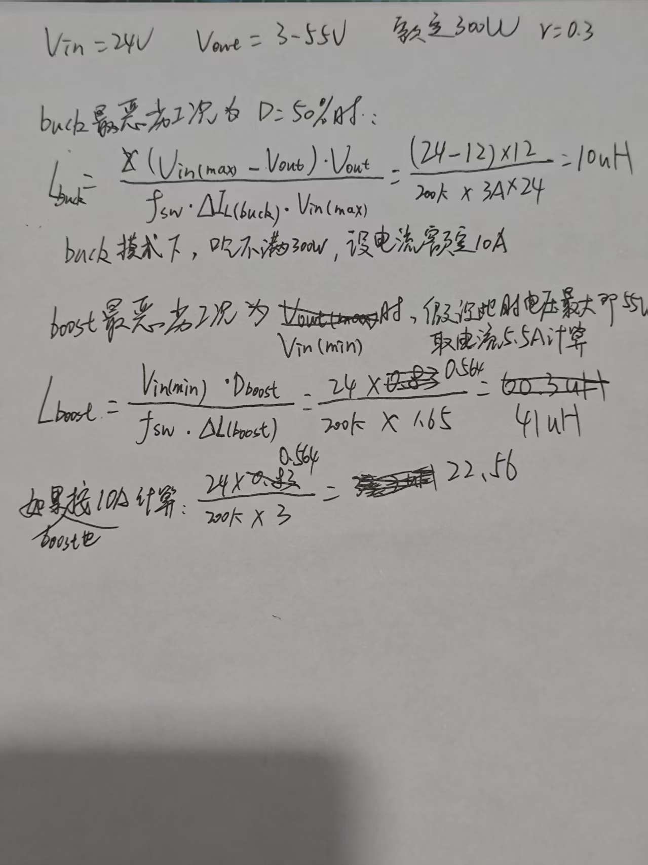
D_{boost} = \frac{V_{out} - V_{in}}{V_{out}} = \frac{55 - 24}{55} \approx 0.564
- Calculate required inductance value:
L_{boost} = \frac{V_{in} \cdot D_{boost}}{f_{sw} \cdot \Delta I_L} = \frac{24 \times 0.564}{200\,\text{k} \times 3.95} \approx 17.1\,\mu\text{H}
(Your calculation of 22.56\,\mu\text{H} at the bottom of the page using 10A input current was conceptually correct — it just didn’t account for the fact that under full 300W load, the actual input current exceeds 13A.)
Which Value to Choose? (10µH vs 15µH vs 22µH)
A four-switch Buck-Boost (FSBB) converter requires a single inductor that must perform well in both Buck and Boost modes. Typically, the Boost mode places more stringent demands on the inductor. Let’s evaluate how each of these three inductors performs under the worst-case Boost condition (with an average current of 13.16A):
1. If choosing 10 µH (your calculated Buck minimum)
- Boost ripple current: \Delta I = \frac{24 \times 0.564}{200\,\text{k} \times 10\mu} \approx 6.77\,\text{A}
- Ripple ratio: 6.77\,\text{A} / 13.16\,\text{A} \approx 51\%
- Evaluation: Not recommended. Ripple exceeds 50%, leading to excessive core loss, high peak switch currents (~16.5A), increased conduction losses, and thermal issues.
2. If choosing 15 µH (a balanced choice)
- Boost ripple current: \Delta I = \frac{24 \times 0.564}{200\,\text{k} \times 15\mu} \approx 4.51\,\text{A}
- Ripple ratio: 4.51\,\text{A} / 13.16\,\text{A} \approx 34\%
- Evaluation: Strongly recommended. A ripple ratio of 30%–40% is widely recognized as the “sweet spot” in industry practice. It strikes an excellent balance between ripple magnitude, inductor size, and dynamic response speed. Under Buck mode, its ripple ratio would be around 20%, which is very stable.
3. If choosing 22 µH (conservative option)
- Boost ripple current: \Delta I \approx 3.07\,\text{A}
- Ripple ratio: 3.07\,\text{A} / 13.16\,\text{A} \approx 23\%
- Evaluation: Acceptable, but with drawbacks. While ripple is smaller, a 22µH inductor will be physically larger and may have higher DCR. More importantly, in Boost mode there exists a right-half-plane zero (RHPZ) — the larger the inductance, the lower the RHPZ frequency, which severely limits control loop bandwidth and results in sluggish transient response during load steps (e.g., jumping from 50W to 300W).
Final Recommendation and Selection Guidelines
In conclusion, selecting 15 µH is the optimal choice. When purchasing or customizing this 15 µH inductor, pay close attention to the following two critical parameters — otherwise, attempting to run at 300W could easily lead to MOSFET failure or inductor saturation:
- Saturation Current (I_{sat}): Must exceed the maximum peak current. Under worst-case conditions, peak current is approximately 13.16\,\text{A} + (4.51\,\text{A}/2) \approx 15.4\,\text{A}. We recommend at least 20% margin, so I_{sat} should be no less than 18A–20A.
- Temperature Rise Current (I_{rms}): Must sustain over 13A RMS continuously. I_{rms} should be at least 15A, and you should aim for an inductor with DCR (DC resistance) below 10\,\text{m}\Omega to minimize heating.
Step 1: Correct Key Design Parameters & Critical Mistake Correction
First, clarify your specs and fix the core error in your boost-mode calculation:
- Fixed input:
Vin = 24V(Vin_min = Vin_max = 24V) - Output range:
3V to 55V, rated power300W, switching frequencyfsw = 200kHz - Critical correction: In boost mode, the inductor carries the input current (not output current). For 300W output at 55V (η=0.9, typical efficiency), the average inductor current is:
IL_avg(boost) = Pout/(η·Vin) = 300/(0.9·24) ≈ 13.9A
Your original calculation used the 5.5A output current, which significantly underestimated the inductor current and overestimated the allowable ripple.
Step 2: Worst-Case Inductance Calculation for 4-Switch Buck-Boost
A 4-switch buck-boost operates in buck mode (Vout < 24V) and boost mode (Vout > 24V). You must calculate the minimum required inductance for both modes, and select the maximum value (plus margin) to satisfy all operating conditions.
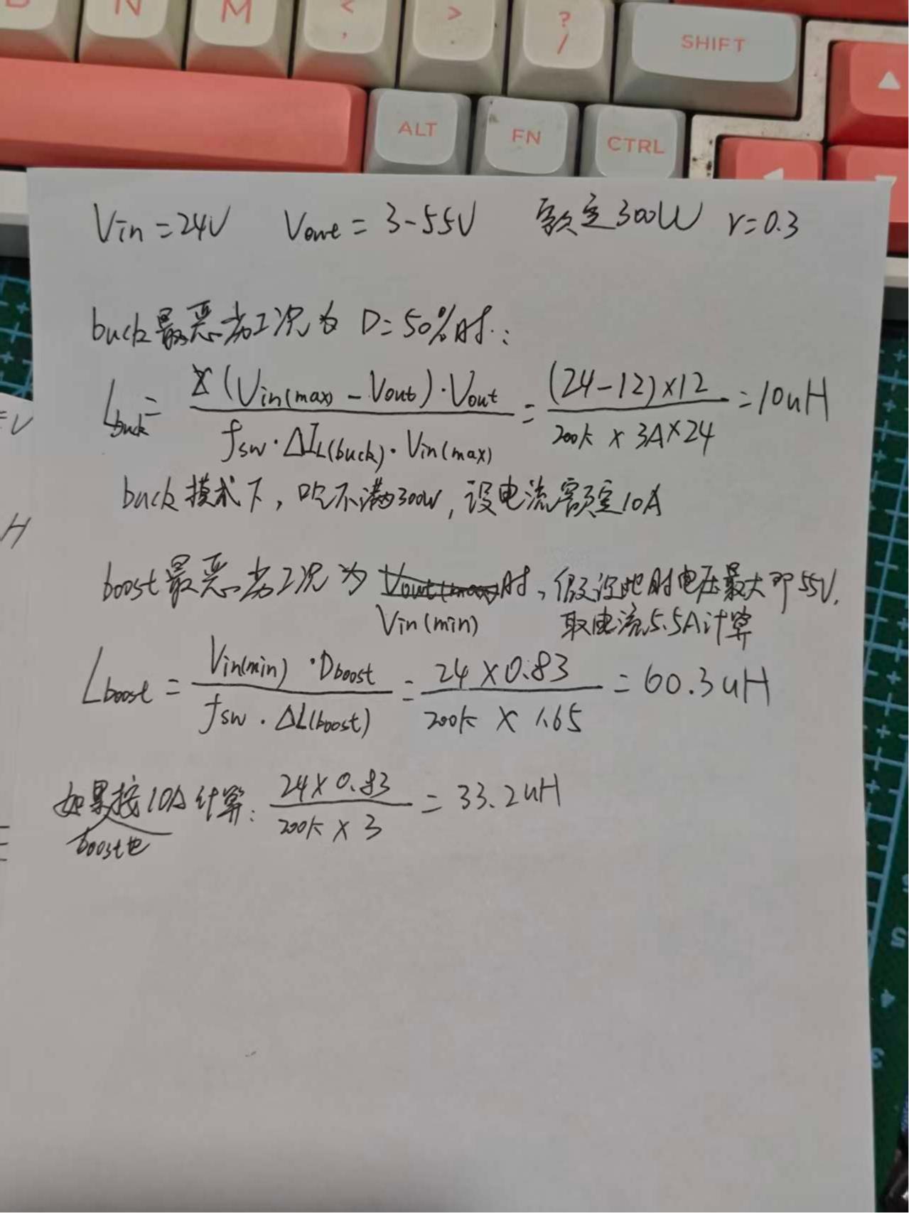
1. Buck Mode Minimum Inductance
Buck mode worst case is at Vout = Vin/2 = 12V (D=50%, maximum inductance requirement for buck). Using your target ripple ΔIL = 3A:
L_{buck(min)} = \frac{(Vin - Vout)·Vout}{fsw·ΔIL·Vin} = \frac{(24-12)·12}{200e3·3·24} = 10μH
2. Boost Mode Minimum Inductance
Boost mode worst case is at maximum Vout=55V (maximum duty cycle, highest inductance requirement). Using the same ΔIL=3A for consistency:
L_{boost(min)} = \frac{Vin·(Vout - Vin)}{fsw·ΔIL·Vout} = \frac{24·(55-24)}{200e3·3·55} ≈ 22.5μH
Step 3: Final Inductance Selection
The boost mode requirement is the limiting factor here. We add 10-20% margin for inductor tolerance, temperature derating, and saturation:
-
Recommended Value: 22μH (standard value)
- Meets the boost mode minimum requirement (~22.5μH) with negligible tolerance margin
- For buck mode, it delivers very low ripple (~1.36A at 12V), reducing output noise and core loss
- Requires an inductor with:
- Saturation current
Isat ≥ 18A(to handle peak current ~15.4A + 20% margin) - RMS current rating
Irms ≥ 14A(for continuous full-load operation) - Low DCR for high efficiency at high current, ferrite core optimized for 200kHz switching
- Saturation current
-
Alternative: 15μH (smaller size, higher ripple tradeoff)
- Acceptable only if you can tolerate higher ripple current (~4.5A in boost mode)
- Requires an inductor with
Isat ≥ 19Ato avoid saturation at peak current ~16.1A - Will have higher core loss and EMI compared to 22μH, only recommended if size is critical
-
Not Recommended: 10μH
- Results in excessive ripple current (~6.7A) in boost mode, leading to severe core loss, high EMI, and high risk of inductor saturation at full load
- Only meets the buck mode requirement, and fails to support boost mode operation at rated power
Final Recommendation
Use a 22μH power inductor with Isat ≥ 18A, Irms ≥ 14A, and low DCR. This is the most robust, standard value that satisfies all operating conditions for your 300W 4-switch buck-boost design.
Boost mode needs to calculate using input current.