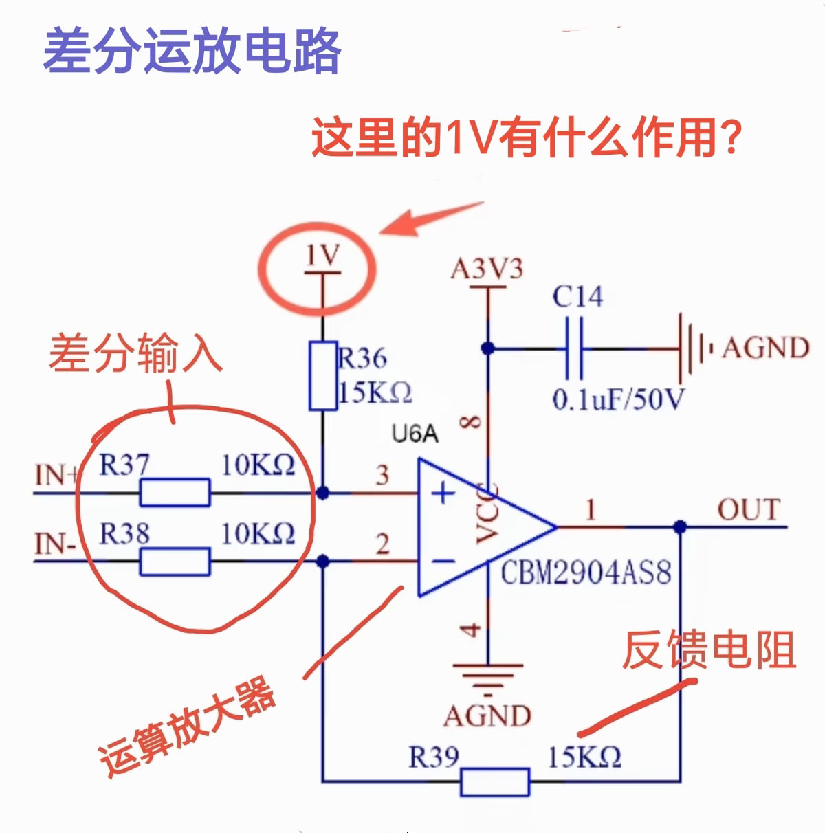
This is a differential operational amplifier circuit. Do you know what the 1V voltage does here?
The basic principle of this op-amp circuit is as follows: R37 and R38 are differential input resistors with equal resistance values of 10 kΩ each. R39 and R36 are feedback resistors, providing a gain ratio of 15 kΩ / 10 kΩ = 1.5. Note that the op-amp is powered by a single supply, so its output range is limited to 0–3.3 V.
In standard differential op-amp circuits, the point labeled “1V” is typically connected directly to AGND (analog ground), resulting in an output given by OUT = A×(IN⁺ − IN⁻). In this circuit, however, the 1V serves as a bias voltage—meaning the amplified differential signal is superimposed onto this 1V reference. Thus, the output becomes OUT = A×(IN⁺ − IN⁻) + 1V.
Those interested can derive this result themselves using the concepts of “virtual open” and “virtual short.”
The OP summarized it very well! Let me add a practical engineering consideration: In a single-supply system, adding this 1V bias is indeed intended to lift the AC signal and prevent clipping of the negative half-cycle. However, in actual PCB design, this 1V reference voltage must be extremely clean, preferably derived from a dedicated voltage reference IC or buffered through an op-amp voltage follower. Additionally, the accuracy and matching of the two resistor pairs R37/R38 and R36/R39 greatly affect the circuit’s common-mode rejection ratio (CMRR), so it’s recommended to use resistors with 1% or even 0.1% tolerance.
Thank you for the post! I’ve been working on a current sensing circuit recently, and I never quite understood why single-supply op-amps are sometimes connected to GND and sometimes to a certain voltage. This explanation cleared it up instantly—it’s to provide DC bias and ensure sufficient dynamic range. May I also ask you: if the circuit is followed by a 3.3V microcontroller’s ADC, would it be better to set this bias voltage at 1.65V (i.e., half of 3.3V)?