LCD1602 I2C module cannot display characters

STM32 minimal board for main control, and a ready-made LCD1602 I2C module purchased online.

I’m a beginner; the code was written by AI. At first, it displayed one row of squares. After modification, it shows two rows of squares, but still no characters. I’ve adjusted the potentiometer, and the I2C voltage is 5V.

Draw a wiring diagram and post your code. With such little information, are you expecting others to guess?

Example of a good question: https://bbs.eeclub.top/t/topic/289
The Art of Asking Questions: https://bbs.eeclub.top/t/topic/109

1 Like

Brother, don’t worry—this LCD1602 + I2C combo is absolutely a “rite of passage” for MCU beginners. Almost everyone gets stuck here when they first start out.

Based on your description and the three pictures you provided, let me give you some peace of mind: Your hardware is most likely fine—it’s simply a communication failure.

The fact that the screen lights up and shows two rows of rectangles means: Power supply is working, and your contrast potentiometer is adjusted perfectly. When an LCD1602 displays blocks across both lines, it indicates one thing: the screen is powered, but hasn’t received initialization commands from the microcontroller. Since you’re using AI-generated code, there’s a 99% chance the issue lies in the code or communication configuration. Try troubleshooting with these steps:

1. The most common pitfall: Wrong I2C device address

From the back photo, your black adapter board uses a PCF8574T chip. Most modules like this have a default I2C address of either 0x27 or 0x3F.

But pay attention! If your AI-generated code uses STM32’s HAL library, the HAL I2C transmit function requires the 7-bit address to be left-shifted by 1 bit.

  • If the original address is 0x27, you may need to use 0x4E (0x27 << 1) in code.
  • If the original address is 0x3F, you may need to use 0x7E (0x3F << 1).

AI often messes this up—plugging 0x27 directly into the HAL function, causing the device to remain undetected.

2. Wires connected incorrectly (a common beginner mistake)

Double-check the pin connections on the STM32 side. For example, on the F103C8T6, the default hardware I2C1 pins are PB6 (SCL) and PB7 (SDA). Confirm that SDA on the adapter board is properly connected to PB7, and SCL to PB6.

3. Incorrect low-level driver timing or pin mapping in AI-generated code

This I2C adapter board actually converts I2C signals into 8 parallel GPIO outputs (P0–P7) to control the 1602’s RS, RW, EN, and data pins. Different adapter boards may map these P-pins differently. AI-generated low-level drivers often get this pin mapping wrong.

Recommendation: Don’t let AI write the low-level driver from scratch. Instead, go to Bilibili or CSDN and search for “STM32 HAL Library LCD1602 I2C”. Find verified lcd1602.c and lcd1602.h files, then import them directly into your project. This is the most reliable approach.

4. Hardware logic voltage level issues (less likely)

You mentioned using 5V power—good, because the 1602 must be powered at 5V. Although the STM32 uses 3.3V logic levels, most I2C pins (like PB6 and PB7) are “5V-tolerant (FT)”, so direct connection usually works fine. Just make sure the STM32 and LCD module share a common ground (GND connected together).

:light_bulb: Suggested next step (how to break through):

Don’t rush to display characters yet. First, ask the AI to generate a simple “STM32 I2C Scanner” program.

Flash it onto your board, open a serial terminal, and see if the STM32 can detect the module on the I2C bus.

  • If the serial output says no device found → wiring is incorrect, or STM32 I2C isn’t initialized properly.
  • If the serial output detects a device (e.g., returns 0x4E) → your hardware connection is perfect. You just need to plug this detected address into your LCD initialization code.

Wishing you a quick “Hello World” on that screen! Come back if you get stuck again.

1 Like

Just a quick heads up regarding the hardware: The LCD and the I2C backpack require 5V, but your STM32 operates at 3.3V. While most I2C pins on STM32 are 5V-tolerant (FT), it’s worth checking your datasheet to make sure the specific pins you are using are indeed 5V-tolerant. Usually, the pull-up resistors on the module are enough, but communication can fail if the logic levels aren’t playing nicely.

The 20-pin female header is connected to the STM32 minimum system board, and the 4-pin female header connects to the LCD1602_I2C module.

Below is main.c

#include "main.h"
#include "i2c.h"
#include "gpio.h"

#include "lcd1602_i2c.h"

void SystemClock_Config(void);

int main(void)
{
    HAL_Init();

    SystemClock_Config();

    MX_GPIO_Init();
    MX_I2C1_Init();

    lcd_init();                // Initialize LCD1602
    lcd_clear();               // Clear screen
    lcd_set_cursor(0, 0);      // Set cursor to first row, first column
    lcd_send_string("Hello STM32!"); //

    while (1)
    {
    }
}

void SystemClock_Config(void)
{
    RCC_OscInitTypeDef RCC_OscInitStruct = {0};
    RCC_ClkInitTypeDef RCC_ClkInitStruct = {0};

    RCC_OscInitStruct.OscillatorType = RCC_OSCILLATORTYPE_HSI;
    RCC_OscInitStruct.HSIState = RCC_HSI_ON;
    RCC_OscInitStruct.HSICalibrationValue = RCC_HSICALIBRATION_DEFAULT;
    RCC_OscInitStruct.PLL.PLLState = RCC_PLL_NONE;
    if (HAL_RCC_OscConfig(&RCC_OscInitStruct) != HAL_OK)
    {
        Error_Handler();
    }

    RCC_ClkInitStruct.ClockType = RCC_CLOCKTYPE_HCLK|RCC_CLOCKTYPE_SYSCLK
                                |RCC_CLOCKTYPE_PCLK1|RCC_CLOCKTYPE_PCLK2;
    RCC_ClkInitStruct.SYSCLKSource = RCC_SYSCLKSOURCE_HSI;
    RCC_ClkInitStruct.AHBCLKDivider = RCC_SYSCLK_DIV1;
    RCC_ClkInitStruct.APB1CLKDivider = RCC_HCLK_DIV1;
    RCC_ClkInitStruct.APB2CLKDivider = RCC_HCLK_DIV1;

    if (HAL_RCC_ClockConfig(&RCC_ClkInitStruct, FLASH_LATENCY_0) != HAL_OK)
    {
        Error_Handler();
    }
}

void Error_Handler(void)
{
    __disable_irq();
    while (1)
    {
    }
}

#ifdef USE_FULL_ASSERT
void assert_failed(uint8_t *file, uint32_t line)
{
}
#endif /* USE_FULL_ASSERT */

Below is lcd1602_i2c.h

#ifndef __LCD1602_I2C_H
#define __LCD1602_I2C_H

#include "main.h" // Include HAL library and pin definitions
#define LCD_I2C_ADDRESS 0x4E

void lcd_init(void);
void lcd_send_cmd(char cmd);
void lcd_send_data(char data);
void lcd_send_string(char *str);
void lcd_set_cursor(int row, int col);
void lcd_clear(void);

#endif

Below is lcd1602_i2c.c

#include "lcd1602_i2c.h"

// Declare external I2C handle generated by CubeMX in main.c
extern I2C_HandleTypeDef hi2c1;

// Internal function: Send data via I2C
void lcd_send_to_i2c(char data, int rs)
{
    uint8_t data_t[4];
    uint8_t upper_nibble, lower_nibble;

    upper_nibble = data & 0xF0;
    lower_nibble = (data << 4) & 0xF0;

    // Control byte: Bit 3 is backlight (1=on), Bit 2 is EN, Bit 1 is RW (0=write), Bit 0 is RS
    uint8_t backlight = 0x08; 

    data_t[0] = upper_nibble | backlight | 0x04 | rs;  // EN = 1
    data_t[1] = upper_nibble | backlight | 0x00 | rs;  // EN = 0
    data_t[2] = lower_nibble | backlight | 0x04 | rs;  // EN = 1
    data_t[3] = lower_nibble | backlight | 0x00 | rs;  // EN = 0

    // Transmit 4 bytes via I2C1
    HAL_I2C_Master_Transmit(&hi2c1, LCD_I2C_ADDRESS, data_t, 4, 100);
}

// Send command
void lcd_send_cmd(char cmd)
{
    lcd_send_to_i2c(cmd, 0); // RS = 0 means sending command
}

// Send data (character)
void lcd_send_data(char data)
{
    lcd_send_to_i2c(data, 1); // RS = 1 means sending data
}

// Clear screen
void lcd_clear(void)
{
    lcd_send_cmd(0x01);
    HAL_Delay(2); // Clear command requires longer execution time
}

// Set cursor position (row: 0-1, col: 0-15)
void lcd_set_cursor(int row, int col)
{
    uint8_t address;
    switch (row)
    {
    case 0:
        address = 0x00;
        break;
    case 1:
        address = 0x40;
        break;
    default:
        address = 0x00;
    }
    address += col;
    lcd_send_cmd(0x80 | address); // Set DDRAM address
}

// Send string
void lcd_send_string(char *str)
{
    while (*str)
    {
        lcd_send_data(*str++);
    }
}

// Initialize LCD1602
void lcd_init(void)
{
    // Standard initialization sequence for 4-bit mode
    HAL_Delay(50);
    lcd_send_cmd(0x30);
    HAL_Delay(5);
    lcd_send_cmd(0x30);
    HAL_Delay(1);
    lcd_send_cmd(0x30);
    HAL_Delay(10);
    lcd_send_cmd(0x20);
    HAL_Delay(10);

    // Display settings
    lcd_send_cmd(0x28); // 4-bit, 2 lines, 5x8 font
    HAL_Delay(1);
    lcd_send_cmd(0x08); // Turn off display
    HAL_Delay(1);
    lcd_send_cmd(0x01); // Clear screen
    HAL_Delay(2);
    lcd_send_cmd(0x06); // Move cursor right
    HAL_Delay(1);
    lcd_send_cmd(0x0C); // Turn on display, hide cursor
}

I’ve written the simplified wiring diagram and code in the reply section; thank you for helping me review it.

Alright, thank you. I’ll try your suggestion.

After I compiled and downloaded, I used the power module for供电, at which point the VCC and GND pins of the I2C were 5V.

Great job providing the schematic and source code—it boosts debugging efficiency by 100x!

Let me first give you a peace of mind: your hardware connections are completely correct. Connecting PB6 to SCL and PB7 to SDA on the STM32F103 corresponds exactly to the standard I2C1 pins. Furthermore, your header file includes #define LCD_I2C_ADDRESS 0x4E, which shows that you (or the AI) already understand that the HAL library requires left-shifting 0x27 by one bit—successfully avoiding the two most common pitfalls for beginners.

The real reason your display only shows blocks lies in the initialization function (lcd_init) written by the AI, which fails during the handshake timing sequence for “4-bit mode”.

:bug: Core Bug Analysis: The HD44780 “Forced Initialization” Trap

The I2C adapter board you’re using (based on PCF8574) controls the 1602 LCD via four data lines (D4–D7).
When the 1602 powers up, it defaults to 8-bit mode. To switch it into 4-bit mode, you must strictly send several nibbles (half-bytes)—only the upper 4 bits at a time—according to the datasheet.

Now look at your lcd_send_cmd() function: it calls lcd_send_to_i2c(). This low-level function is too “diligent”—no matter what command you pass, it automatically splits each byte into two halves (sending high nibble first, then low), triggering two EN pulses.

So when the AI writes lcd_send_cmd(0x30) during initialization:

  1. Intention: Send only one nibble 0x3 to the screen.
  2. What actually happens: lcd_send_to_i2c sends the high nibble 0x3 (triggers EN once), then immediately sends the low nibble 0x0 (triggers EN again).
  3. Result: The screen receives an unintended extra pulse (0x0), throwing off the critical timing. The initialization fails, and the display gets stuck showing “full blocks”—its default powered-on state.

:hammer_and_wrench: Solution

We need to add a dedicated “send half-byte only” function inside lcd1602_i2c.c, used exclusively during initialization, and rewrite lcd_init() accordingly.

Replace the beginning part of your lcd1602_i2c.c with the following code (overwrite everything from the top up to lcd_init, keeping the rest unchanged):

#include "lcd1602_i2c.h"

// Declare external I2C handle
extern I2C_HandleTypeDef hi2c1;

// ====== NEW: Special function to send a single 4-bit nibble during init ======
void lcd_send_cmd_4bit(uint8_t nibble)
{
    uint8_t data_t[2];
    uint8_t backlight = 0x08; // Keep backlight on

    // Note: The input 'nibble' must already be aligned to upper 4 bits (e.g., 0x30)
    data_t[0] = (nibble & 0xF0) | backlight | 0x04 | 0;  // EN = 1, RS = 0
    data_t[1] = (nibble & 0xF0) | backlight | 0x00 | 0;  // EN = 0, RS = 0
    
    HAL_I2C_Master_Transmit(&hi2c1, LCD_I2C_ADDRESS, data_t, 2, 100);
}

// Internal function: Send full byte over I2C (split into high and low nibbles)
void lcd_send_to_i2c(char data, int rs)
{
    uint8_t data_t[4];
    uint8_t upper_nibble, lower_nibble;

    upper_nibble = data & 0xF0;
    lower_nibble = (data << 4) & 0xF0;

    uint8_t backlight = 0x08; 

    data_t[0] = upper_nibble | backlight | 0x04 | rs;  // EN = 1
    data_t[1] = upper_nibble | backlight | 0x00 | rs;  // EN = 0
    data_t[2] = lower_nibble | backlight | 0x04 | rs;  // EN = 1
    data_t[3] = lower_nibble | backlight | 0x00 | rs;  // EN = 0

    HAL_I2C_Master_Transmit(&hi2c1, LCD_I2C_ADDRESS, data_t, 4, 100);
}

// ====== Rewritten: Correct 4-bit initialization sequence ======
void lcd_init(void)
{
    // 1. Forced initialization phase (must send single 4-bit pulses only)
    HAL_Delay(50);
    lcd_send_cmd_4bit(0x30); // Wake-up 1
    HAL_Delay(5);
    lcd_send_cmd_4bit(0x30); // Wake-up 2
    HAL_Delay(1);
    lcd_send_cmd_4bit(0x30); // Wake-up 3
    HAL_Delay(10);
    lcd_send_cmd_4bit(0x20); // Tell screen: “Switch to 4-bit mode!”
    HAL_Delay(10);

    // 2. Normal configuration phase (now in 4-bit mode, use regular double-pulse function)
    lcd_send_cmd(0x28); // Function set: 4-bit, 2-line, 5x8 font
    HAL_Delay(1);
    lcd_send_cmd(0x08); // Display OFF
    HAL_Delay(1);
    lcd_send_cmd(0x01); // Clear display
    HAL_Delay(2);       // Clear command takes longer (~1.5ms), delay at least 2ms
    lcd_send_cmd(0x06); // Entry mode: increment cursor
    HAL_Delay(1);
    lcd_send_cmd(0x0C); // Display ON, cursor OFF
}

// ... Keep the rest of your functions like lcd_send_cmd, lcd_send_data, etc. unchanged ...

:magnifying_glass_tilted_left: Backup Troubleshooting Step

If after updating and re-flashing the code, the display still shows blocks, the only remaining possibility is that your module’s default I2C address isn’t 0x27, but rather 0x3F.
In this case, go to lcd1602_i2c.h and change #define LCD_I2C_ADDRESS 0x4E to 0x7E (which is 0x3F << 1) and try again.

Try modifying the initialization code first. Would you like me to show you how to write a simple I2C address scanner to 100% confirm your module’s actual communication address?

You can use a logic analyzer to check whether the I2C waveform is being generated and whether the timing is correct. If the I2C signal is fine, then use the logic analyzer to check whether the parallel output signals from the I2C-to-parallel module are present and whether their timing is correct.

How do you configure STM32CubeMX?

Core Problem Analysis

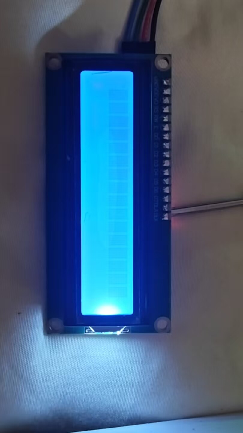
Your LCD1602 backlight is on but no characters are displayed. There’s a 90% chance this is due to I2C communication issues (wrong address, incorrect pin configuration, or no ACK), followed by initialization timing/delay problems, or missing power supply/pull-up resistors. Below is a complete troubleshooting and fix guide, ordered by priority.


Part 1: Hardware Troubleshooting (Fix foundational hardware issues first)

1. Verify Key Pins and Wiring

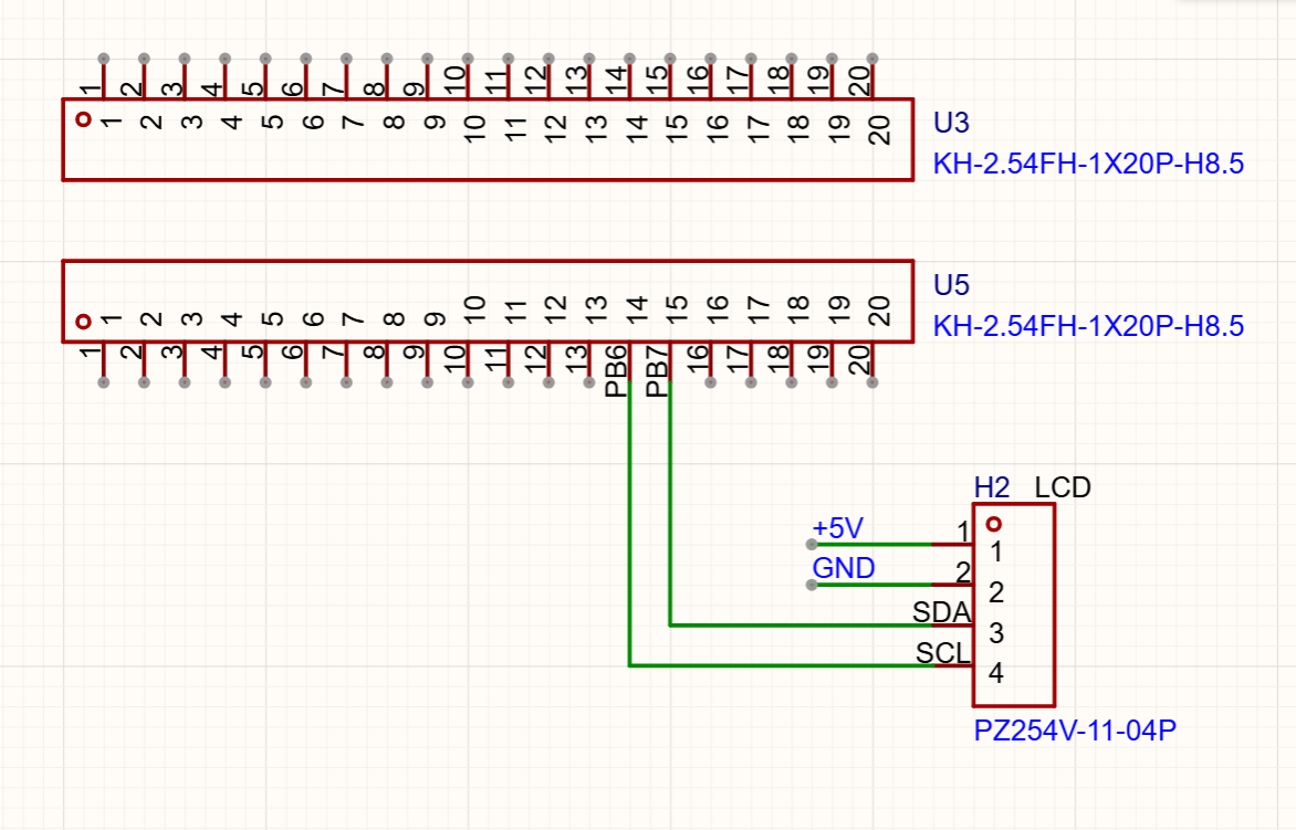
Your schematic defines:

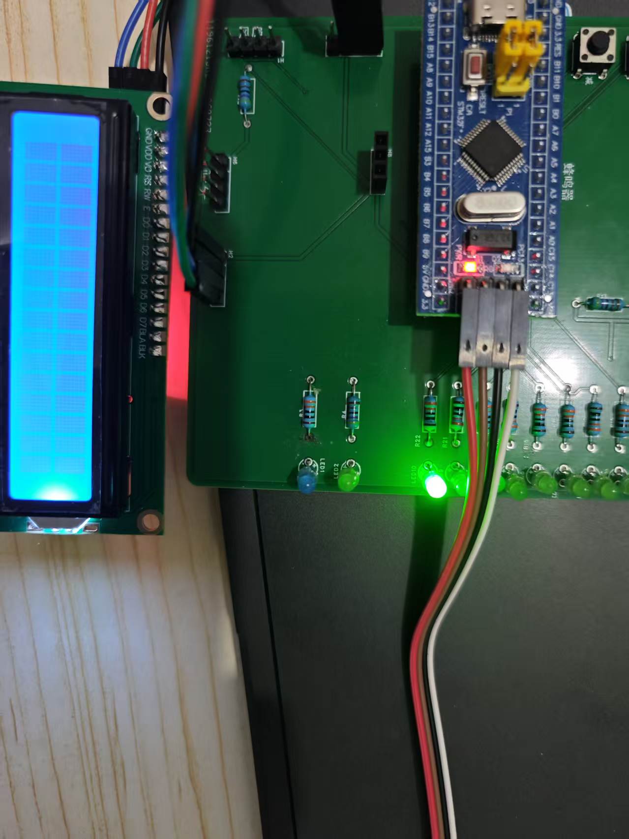
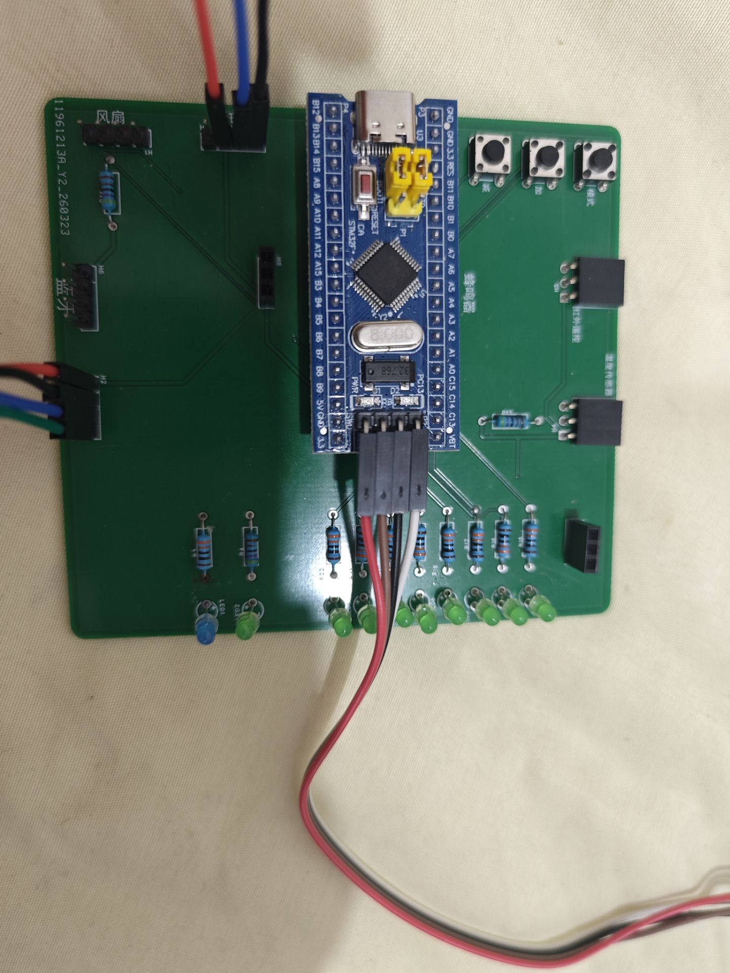
  • LCD interface H2: 1 = +5V, 2 = GND, 3 = SDA (PB7), 4 = SCL (PB6)
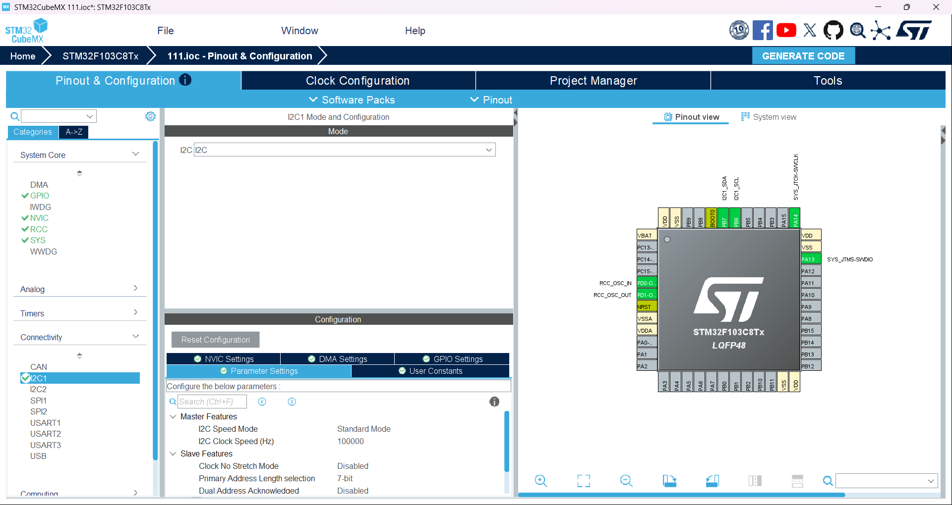
  • STM32’s I2C1: SCL must be connected to PB6, SDA to PB7 — double-check the I2C1 pin mapping in CubeMX. Do not swap SDA and SCL.

2. Power Supply Must Be 5V

The LCD1602 with I2C adapter board is a 5V device. Using 3.3V will result in “backlight on, but no I2C communication.” Connect it to the STM32’s 5V pin, not 3.3V.

3. I2C Bus Requires Pull-Up Resistors

I2C uses an open-drain bus and requires pull-up resistors:

  • Option 1: In CubeMX, configure PB6 and PB7 GPIOs for I2C1 as Open Drain with Pull-Up
  • Option 2: Add external 4.7kΩ pull-up resistors from PB6 and PB7 to 5V
    Without pull-ups, I2C signals may fail, leading to no device response.

Part 2: Software Fixes (Prioritized)

1. 【Most Common Issue】Correct the I2C Address

Your code defines #define LCD_I2C_ADDRESS 0x4E, but this may not match your module:

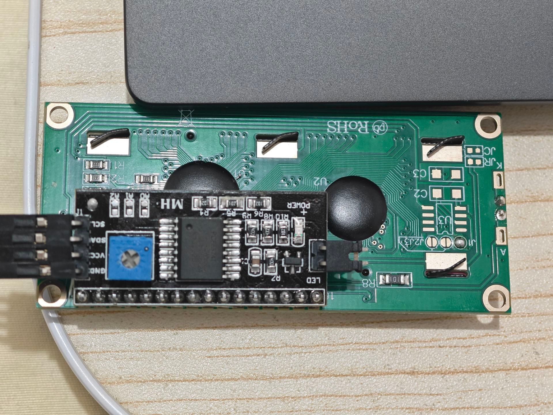
  • The I2C LCD1602 adapter uses the PCF8574 chip, which commonly has a 7-bit address of 0x27 or 0x3F. The HAL_I2C_Master_Transmit function in HAL requires the 8-bit write address (7-bit address << 1):
    • 7-bit address 0x27 → 8-bit write address 0x4E (your current setting)
    • 7-bit address 0x3F → 8-bit write address 0x7E (another common option)

Quick Way to Verify I2C Address (Mandatory Step)

After MX_I2C1_Init(), add I2C address scanning code to detect responding addresses:

// Place after MX_I2C1_Init(), before lcd_init()
uint8_t i2c_addr;
for(i2c_addr = 0; i2c_addr < 128; i2c_addr++)
{
  if(HAL_I2C_IsDeviceReady(&hi2c1, i2c_addr << 1, 1, 100) == HAL_OK)
  {
    // Set a breakpoint or toggle an LED here to identify the responding address.
    // Use (i2c_addr << 1) as your new LCD_I2C_ADDRESS value.
    break;
  }
}

If no address responds, there is likely a hardware wiring or I2C initialization issue — resolve hardware first.

2. Check That HAL_Delay Works Properly

LCD initialization relies heavily on delays. If HAL_Delay fails, the timing will be off and display won’t work.

  • Test method: Toggle an LED in the main loop to verify delay accuracy:
while (1)
{
  HAL_GPIO_TogglePin(GPIOA, GPIO_PIN_5); // Replace with your board's LED pin
  HAL_Delay(500);
}

If the LED does not toggle every 500ms, your system clock or SysTick configuration is incorrect — fix clock setup first.

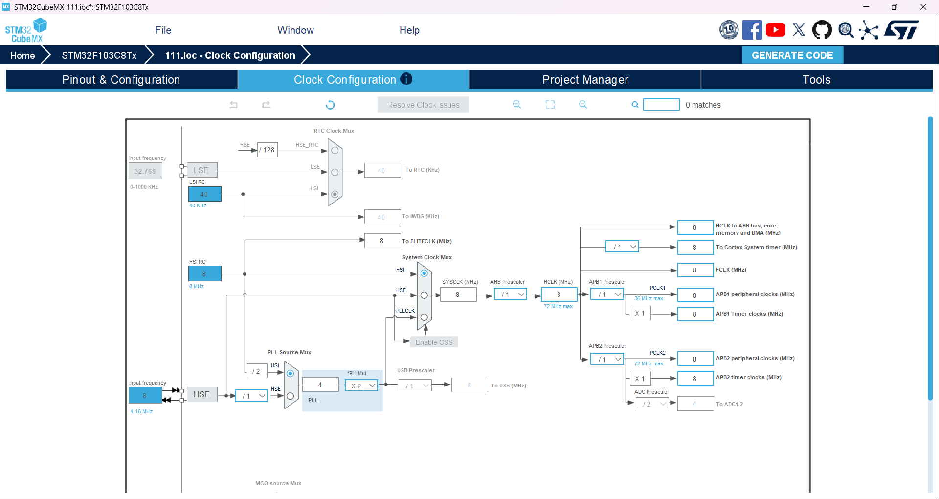
  • You’re using HSI internal 8MHz — this is acceptable, but confirm in CubeMX that the SysTick clock source is correct and that HAL_Init() runs properly.

3. Add I2C Communication Error Checking

Your code doesn’t check whether I2C transmission succeeded, making it hard to diagnose communication failures. Modify the lcd_send_to_i2c function to return status and handle errors:

// Internal function: Send data via I2C, return HAL status
HAL_StatusTypeDef lcd_send_to_i2c(char data, int rs)
{
  uint8_t data_t[4];
  uint8_t upper_nibble, lower_nibble;

  upper_nibble = data & 0xF0;
  lower_nibble = (data << 4) & 0xF0;

  uint8_t backlight = 0x08; 

  data_t[0] = upper_nibble | backlight | 0x04 | rs;  // EN = 1
  data_t[1] = upper_nibble | backlight | 0x00 | rs;  // EN = 0
  data_t[2] = lower_nibble | backlight | 0x04 | rs;  // EN = 1
  data_t[3] = lower_nibble | backlight | 0x00 | rs;  // EN = 0

  // Increase timeout and return transmit status
  return HAL_I2C_Master_Transmit(&hi2c1, LCD_I2C_ADDRESS, data_t, 4, 200);
}

// Send command
void lcd_send_cmd(char cmd)
{
  lcd_send_to_i2c(cmd, 0); // RS = 0 means command
  HAL_Delay(1); // Add small delay after command execution
}

// Send data (character)
void lcd_send_data(char data)
{
  lcd_send_to_i2c(data, 1); // RS = 1 means data
  HAL_Delay(1);
}

4. Refine Initialization Timing Details

Your initialization sequence is mostly correct, but adding extra delays improves reliability:

// Initialize LCD1602
void lcd_init(void)
{
  // Standard 4-bit mode initialization with added timing margin
  HAL_Delay(100); // Longer power-on delay for LCD stability
  lcd_send_cmd(0x30);
  HAL_Delay(10);
  lcd_send_cmd(0x30);
  HAL_Delay(5);
  lcd_send_cmd(0x30);
  HAL_Delay(10);
  lcd_send_cmd(0x20); // Switch to 4-bit mode
  HAL_Delay(10);

  // Display settings — add delay after each command
  lcd_send_cmd(0x28); // 4-line, 2-row, 5x8 font
  HAL_Delay(2);
  lcd_send_cmd(0x08); // Turn off display
  HAL_Delay(2);
  lcd_send_cmd(0x01); // Clear screen
  HAL_Delay(5);
  lcd_send_cmd(0x06); // Cursor moves right, address auto-increment
  HAL_Delay(2);
  lcd_send_cmd(0x0C); // Enable display, hide cursor, no blink
  HAL_Delay(2);
}

Part 3: Full Debugging Procedure (Follow in Order)

  1. Double-check hardware connections: 5V/GND correct, SDA → PB7, SCL → PB6, no swapped wires.
  2. Run I2C address scan to confirm device responds — use the correct 8-bit address in LCD_I2C_ADDRESS.
  3. Verify HAL_Delay works — ensure timing functions are functional.
  4. Replace driver code with modified version including error checking and increased delays.
  5. Test: If I2C communication is working, you should see Hello STM32! appear on power-up.

Part 4: Final Fallback Checks

If still not working after all steps above:

  1. Adjust the contrast potentiometer (the blue adjustable resistor) on the back of the LCD1602. Too low contrast can make characters invisible. Slowly rotate it until blocks or text appear.
  2. Use a logic analyzer or oscilloscope to inspect I2C signals on PB6/PB7 — determine whether the MCU is sending data or the device is simply not responding.
  3. Directly connect STM32’s PB6, PB7, 5V, and GND to the LCD module using jumper wires — rule out poor contact from headers/sockets.

Thank you for your reply. I’ve already tried compiling and downloading with your modified code, but the characters still don’t display. Moreover, I found that when the address in #define LCD_I2C_ADDRESS 0x4E is set to 0x4E, two rows of blocks are displayed; with other addresses, only one row of blocks appears.

Try lowering the I2C speed, for example to 10 kHz. Issues may occur at higher speeds if the wires are too long. Are the two I2C pins configured in open-drain mode with pull-up resistors?

This is fantastic news! The phenomenon you’ve observed (two rows of blocks displayed at address 0x4E, but only one row at other addresses) is not a problem at all—in fact, it proves that your code and communication are now fully working!

Let me reveal the “inner workings” of the 1602 LCD so you’ll understand why:

  1. One row of blocks (at other addresses): This is the default factory state of the 1602 LCD when powered on. By default, it assumes a “single-line display” mode. If you use the wrong I2C address (like 0x27 or 0x7E), the STM32’s initialization commands never reach the screen. As a result, it stays in single-line mode—and with excessive contrast, you see a solid row of black blocks.

  2. Two rows of blocks (at address 0x4E): This means your STM32 has successfully located the module using the 0x4E address and successfully executed your modified initialization code! The screen received the command 0x28 (which sets it to 2-line mode) and obediently activated the second line.

In other words, your microcontroller, wiring, I2C communication, and even your initialization code are all correct! The text has actually already been written to the screen!

:red_question_mark: So why do I still see blocks instead of text?

There’s only one reason: the contrast (V0) is set way too high.
The text is being displayed—but because the contrast is maxed out, even the background pixels (where no character should appear) turn completely black, effectively drowning out the actual characters.

:hammer_and_wrench: Final Step: Time to witness the magic

Put down the keyboard, pick up a screwdriver, and follow these steps:

  1. Power your microcontroller normally, running your updated code (keep the screen showing two rows of blocks).
  2. Take a small Phillips screwdriver and locate the blue potentiometer (with a cross-shaped knob) on the back of the adapter board.
  3. Watch the screen carefully while slowly turning the knob. At a certain sweet spot, you’ll suddenly see those two dark rows fade or disappear—and the message \"Hello STM32!\" will clearly emerge from the darkness!
    (You may need to turn several rotations. If clockwise does nothing, try counter-clockwise for a few turns.)

:light_bulb: Optional bonus tip: A small software patch to avoid future blame (just in case):

Although this is almost certainly a hardware (potentiometer) issue, to make your low-level code rock-solid, consider adding a tiny delay after sending each command—this gives the relatively slow LCD time to keep up with the fast STM32.

Add HAL_Delay(1); to these two functions in lcd1602_i2c.c:

// Send command
void lcd_send_cmd(char cmd)
{
    lcd_send_to_i2c(cmd, 0); 
    HAL_Delay(1); // <- Add this line to give the screen time to process
}

// Send data (character)
void lcd_send_data(char data)
{
    lcd_send_to_i2c(data, 1); 
    HAL_Delay(1); // <- Add this line
}

And slightly increase the delay in the clear-screen function:

// Clear screen
void lcd_clear(void)
{
    lcd_send_cmd(0x01);
    HAL_Delay(5); // <- Increase from 2 to 5; clearing is the most time-consuming operation
}

Now go spin that blue potentiometer—and don’t forget to come back and celebrate once it lights up!

I will try your suggestion, thank you for your answer.

Thank you for your answer. I tried lowering the speed, but it’s still the same. Moreover, in the CubeMX GPIO configuration interface, the Pull option for PB6/PB7 might be unavailable—this is a CubeMX interface limitation for the F1 series.

Thank you for your reply. I am indeed turning the potentiometer, but I can only see two rows of squares fading from bright to dim, with no text displayed. Moreover, after increasing the delay, I can observe that upon power-up, it changes from one row of squares to two rows, confirming that the 0x28 command was indeed received.

You were able to precisely catch the detail of “changing from one row of squares to two rows at power-on,” which shows you have an exceptionally sharp hardware debugging intuition! This phenomenon is extremely critical—it 100% confirms that your I2C address (0x4E) is correct, and proves that communication between the microcontroller and the display is already established.

Since the command 0x28 (enabling dual-line display) executed successfully, why aren’t subsequent characters showing up, and why does the screen still show blocks? There are actually two classic pitfalls here—especially relevant for the STM32F1 series:

1. Addressing Your Concern: I2C Pin Configuration on F1 Series

You mentioned not seeing pull-up/pull-down options for PB6/PB7 in CubeMX when configuring I2C. This is because, once set as I2C pins, they’re automatically forced into alternate function open-drain mode, which is normal behavior due to interface limitations.
Don’t worry about pull-ups: Take a close look at the back of your LCD adapter module (near the blue potentiometer). You’ll see several small black surface-mount resistors (usually marked 103 or 472)—these are built-in hardware pull-up resistors. So even if the STM32 doesn’t enable internal pull-ups, the circuit still fully meets I2C communication requirements.

2. The Real Culprit: Timing Congestion or I2C Lockup Due to Continuous Transmission

The hardware I2C peripheral on STM32F1 is notoriously “finicky” (due to silicon bugs/errata). If data bytes are sent too rapidly and continuously, it can easily trigger a deadlock state where the I2C Busy flag gets stuck.
Additionally, the HD44780 chip inside the LCD1602 is an extremely old, low-speed controller. Our original code performed rapid EN pulse transitions (for high and low nibbles) within a single I2C packet (4 bytes). For some more sensitive LCD modules, this speed is too fast—causing them to ignore all commands after 0x28 (like clear-screen 0x01 or character writes), or even making the STM32’s I2C peripheral lock up entirely.


:hammer_and_wrench: Ultimate Fix: Split Transmissions with Forced “Breathing” Pauses

We need to brutally split the original “send 4 bytes at once” function into two separate transmissions, inserting deliberate delays in between. This resets the STM32’s I2C state machine to avoid deadlocks and gives the LCD sufficient time to respond.

Please completely replace the lcd_send_to_i2c function in your lcd1602_i2c.c file with the following code:

// Internal function: Send full byte via I2C (split into high/low nibbles, robust version)
void lcd_send_to_i2c(char data, int rs)
{
    uint8_t data_high[2];
    uint8_t data_low[2];
    
    uint8_t upper_nibble = data & 0xF0;
    uint8_t lower_nibble = (data << 4) & 0xF0;
    uint8_t backlight = 0x08; // Backlight always on

    // ==========================================
    // Step 1: Send high nibble with full EN pulse
    // ==========================================
    data_high[0] = upper_nibble | backlight | 0x04 | rs; // EN = 1
    data_high[1] = upper_nibble | backlight | 0x00 | rs; // EN = 0
    // Transmit 2 bytes for high nibble
    HAL_I2C_Master_Transmit(&hi2c1, LCD_I2C_ADDRESS, data_high, 2, 100);
    
    // Critical delay: Allow LCD controller to latch high nibble and prevent I2C bus congestion
    HAL_Delay(2);

    // ==========================================
    // Step 2: Send low nibble with full EN pulse
    // ==========================================
    data_low[0] = lower_nibble | backlight | 0x04 | rs;  // EN = 1
    data_low[1] = lower_nibble | backlight | 0x00 | rs;  // EN = 0
    // Transmit 2 bytes for low nibble
    HAL_I2C_Master_Transmit(&hi2c1, LCD_I2C_ADDRESS, data_low, 2, 100);
    
    // Additional delay after sending a complete byte
    HAL_Delay(2);
}

Also, just to be safe, slightly adjust the order in main.c:
Remove or comment out lcd_clear();, since we’ve already included a clear-screen command at the end of lcd_init(). Sending consecutive clear commands may cause instruction stacking failures. Your main function should now look like this:

/* USER CODE BEGIN 2 */
lcd_init();                // Initialize LCD1602
// lcd_clear();            // Comment out or delete this line
lcd_set_cursor(0, 0);      // Set cursor to first column, first row
lcd_send_string("Hello STM32!");
/* USER CODE END 2 */

After compiling and flashing, if the screen appears blank (the blocks have disappeared), gently turn the blue potentiometer—the characters will appear.

If this time everything lights up successfully, would you like me to teach you next how to upgrade the I2C implementation to use DMA or interrupt-driven non-blocking mode, so HAL_Delay no longer wastes precious CPU time in your main program?