Hardware Environment: Raspberry Pi 4 Model B Rev 1.5 · Debian 12 Bookworm · Kernel 6.12.25
Test Date: April 2026
Author: zeruns (https://blog.zeruns.com/)
Note: This article was written by AI, for reference only (Hermes Agent + DeepSeek V4 Flash)
Table of Contents
- GPIO Basics
- Environment Setup & Tools
- GPIO Input/Output (Shell Method)
- GPIO Input/Output (Python Method)
- I2C Communication
- SPI Communication
- Integrated Examples
- Notes & Troubleshooting
1. GPIO Basics
1.1 What is GPIO
GPIO (General Purpose Input/Output) refers to a set of programmable pins on a microprocessor. Through software control, each pin can be configured as:
- Output mode: Output high (3.3V) or low (0V) logic levels to control devices like LEDs, relays, and buzzers
- Input mode: Read external signal states (high/low), useful for reading buttons or sensor outputs
- Alternate functions: Dedicated protocols such as I2C, SPI, UART, PWM, etc.
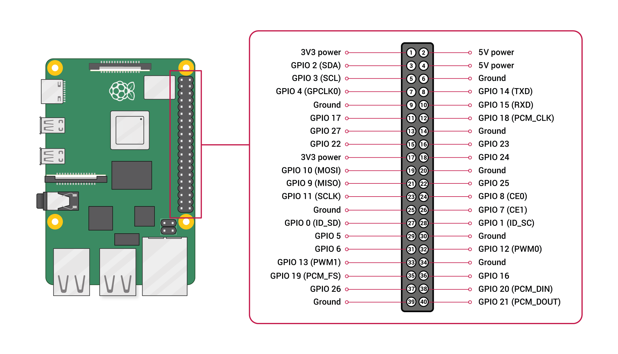
1.2 Raspberry Pi 4B Pin Layout
The Raspberry Pi 4B features a 40-pin expansion header, with three numbering schemes:
| Numbering Scheme | Description | Typical Libraries |
|---|---|---|
| Physical Pin (Board) | Numbered 1 to 40, starting from top-left as 1 | RPi.GPIO setmode(GPIO.BOARD) |
| BCM Numbering | Broadcom chip GPIO numbers, e.g., GPIO17 | RPi.GPIO setmode(GPIO.BCM), libgpiod |
| wiringPi Numbering | Custom wiringPi numbering (deprecated) | wiringPi library |
40-Pin Function Diagram
                    ┌─────────────────────────────┐
                    │  🥝 Raspberry Pi 4B 40-Pin Layout   │
  3.3V  (01) ──●  ●── (02)  5V                    │
 GPIO2  (03) ──●  ●── (04)  5V                    │
 GPIO3  (05) ──●  ●── (06)  GND                   │
 GPIO4  (07) ──●  ●── (08)  GPIO14 (UART TX)      │
   GND  (09) ──●  ●── (10)  GPIO15 (UART RX)      │
GPIO17  (11) ──●  ●── (12)  GPIO18 (PWM0)         │
GPIO27  (13) ──●  ●── (14)  GND                   │
GPIO22  (15) ──●  ●── (16)  GPIO23                │
  3.3V  (17) ──●  ●── (18)  GPIO24                │
GPIO10 (19) ──●  ●── (20)  GND  (SPI_MOSI)        │
 GPIO9 (21) ──●  ●── (22)  GPIO25 (SPI_MISO)      │
GPIO11 (23) ──●  ●── (24)  GPIO8  (SPI_SCLK)      │
   GND (25) ──●  ●── (26)  GPIO7  (SPI_CE0)       │
 GPIO0 (27) ──●  ●── (28)  GPIO1  (ID_SDA / I2C)  │
 GPIO5 (29) ──●  ●── (30)  GND                    │
 GPIO6 (31) ──●  ●── (32)  GPIO12 (PWM0)          │
GPIO13 (33) ──●  ●── (34)  GND                    │
GPIO19 (35) ──●  ●── (36)  GPIO16                 │
GPIO26 (37) ──●  ●── (38)  GPIO20                 │
   GND (39) ──●  ●── (40)  GPIO21                 │
                    └─────────────────────────────┘
Main Pin Functions of Raspberry Pi 4B
| Physical Pin | BCM Number | Function | Physical Pin | BCM Number | Function |
|---|---|---|---|---|---|
| 1 | — | 3.3V | 2 | — | 5V |
| 3 | GPIO2 | I2C1 SDA | 4 | — | 5V |
| 5 | GPIO3 | I2C1 SCL | 6 | — | GND |
| 7 | GPIO4 | — | 8 | GPIO14 | UART TX |
| 9 | — | GND | 10 | GPIO15 | UART RX |
| 11 | GPIO17 | — | 12 | GPIO18 | PCM_CLK / PWM0 |
| 13 | GPIO27 | — | 14 | — | GND |
| 15 | GPIO22 | — | 16 | GPIO23 | — |
| 17 | — | 3.3V | 18 | GPIO24 | — |
| 19 | GPIO10 | SPI0 MOSI | 20 | — | GND |
| 21 | GPIO9 | SPI0 MISO | 22 | GPIO25 | — |
| 23 | GPIO11 | SPI0 SCLK | 24 | GPIO8 | SPI0 CE0 |
| 25 | — | GND | 26 | GPIO7 | SPI0 CE1 |
| 27 | GPIO0 | ID_SDA (EEPROM) | 28 | GPIO1 | ID_SCL (EEPROM) |
| 29 | GPIO5 | — | 30 | — | GND |
| 31 | GPIO6 | — | 32 | GPIO12 | PWM0 |
| 33 | GPIO13 | PWM1 | 34 | — | GND |
| 35 | GPIO19 | PCM_FS / PWM1 | 36 | GPIO16 | — |
| 37 | GPIO26 | — | 38 | GPIO20 | PCM_DIN |
| 39 | — | GND | 40 | GPIO21 | PCM_DOUT |
1.3 Important Notes
- Logic Levels: Raspberry Pi GPIO operates at 3.3V logic and must not be directly connected to 5V signals
- Current Limits: Each GPIO pin can source about 16mA, and all GPIOs combined should not exceed 50mA
- Default State: Most GPIOs default to input mode, some with internal pull-up/down resistors
- 3.3V Pins (01/17): Maximum output current ~500mA
- 5V Pins (02/04): Powered directly from USB-C supply; current depends on power adapter
2. Environment Setup & Tools
2.1 Pre-Installed Tools and Libraries
This guide was tested on Debian 12 Bookworm. The following tools are pre-installed:
| Tool/Library | Version | Purpose |
|---|---|---|
| libgpiod / gpioset / gpioget | 1.6.3 | Shell-based GPIO control |
| python3-libgpiod | 1.6.3 | Python bindings for libgpiod |
| RPi.GPIO | 0.7.2 | Classic Python GPIO library |
| smbus2 | Installed | Python I2C communication |
| spidev | Installed | Python SPI communication |
| pigpiod | 1.79 | GPIO daemon (PWM/remote control) |
| i2c-tools | 4.3 | I2C device scanning |
2.2 Installing Required Tools
If any tools are missing, install them using:
# Basic GPIO tools
sudo apt install gpiod libgpiod-dev python3-libgpiod

# I2C tools
sudo apt install i2c-tools

# Python libraries
pip install RPi.GPIO smbus2 spidev gpiozero

# pigpio daemon (recommended for hardware PWM)
sudo apt install pigpio pigpiod
sudo systemctl enable pigpiod --now
2.3 Enabling I2C / SPI Interfaces
Use raspi-config to enable:
sudo raspi-config
Menu path:
Interface Options → I2C → Enable → Yes
Interface Options → SPI → Enable → Yes
Alternatively, manually edit /boot/firmware/config.txt (Debian 12):
# Manually add
sudo tee -a /boot/firmware/config.txt <<EOF
dtparam=i2c_arm=on
 dtparam=spi=on
 EOF

 # Restart to apply
 sudo reboot
Verify enabling success:
 # Check I2C
 ls /dev/i2c*
 # Output: /dev/i2c-20  /dev/i2c-21

 # Check SPI (after enabling)
 ls /dev/spi*
 # Output: /dev/spidev0.0  /dev/spidev0.1
2.4 View all gpiochip
 $ gpioinfo
 gpiochip0 - 58 lines:
         line   0:     "ID_SDA"       unused   input  active-high
         line   1:     "ID_SCL"       unused   input  active-high
         line   2:      "GPIO2"       unused   input  active-high
         ...
The BCM2711 chip on Raspberry Pi 4B provides one gpiochip0 with 58 GPIOs, but only GPIO0-GPIO27 are exposed via the 40-pin header.
3. GPIO Input/Output (Shell Method)
3.1 libgpiod Toolkit
It is recommended to use the libgpiod tools, which do not depend on wiringPi and represent the current mainstream solution.
Main Commands:
| Command | Function | Example |
|---|---|---|
gpioinfo |
View all GPIO states | gpioinfo |
gpioset |
Set GPIO output level | gpioset 0 17=1 |
gpioget |
Read GPIO input level | gpioget 0 17 |
gpiomon |
Monitor GPIO events | gpiomon 0 17 |
Format Description:
gpioset <chip> <pin>=<va>chipis usually 0 (gpiochip0), andpin` refers to the BCM numbering
3.2 Output: Blinking an LED
Connect the positive lead (longer leg) of an LED through a 330Ω resistor to GPIO17 (physical pin 11), and the negative lead (shorter leg) to GND (physical pin 9).
# Set GPIO17 to high → LED on
gpioset 0 17=1

# Set GPIO17 to low → LED off
gpioset 0 17=0
3.3 Input: Reading Button State
Connect one end of a push button to GPIO18 (physical pin 12), and the other end to GND (physical pin 14).
# Read GPIO18 level (requires external pull-up or internal pull-up enabled)
gpioget 0 18
# Output: 1 (button not pressed, high level)
# Output: 0 (button pressed, low level)
3.4 View All Pin States
# View all pins
gpioinfo

# View specific pin (BCM number 17)
gpioinfo | grep "GPIO17"
# Output: line  17:      "GPIO17"       "myapp"   output  active-high
3.5 gpioset: Setting Pull-up/Pull-down
libgpiod 1.6 supports setting bias when requesting:
# Set GPIO17 as output, initial high, with pull-up
gpioset --bias=enable 0 17=1
4. GPIO Input/Output (Python Methods)
4.1 Using RPi.GPIO (Classic Library)
RPi.GPIO is the most commonly used Python GPIO library—simple and intuitive.
4.1.1 Output: Blinking LED
import RPi.GPIO as GPIO
import time

# Use BCM pin numbering
GPIO.setmode(GPIO.BCM)

# Set GPIO17 as output
GPIO.setup(17, GPIO.OUT)

# Blink LED 5 times
for _ in range(5):
    GPIO.output(17, GPIO.HIGH)  # Turn on
    time.sleep(0.5)
    GPIO.output(17, GPIO.LOW)   # Turn off
    time.sleep(0.5)

# Clean up
GPIO.cleanup()
4.1.2 Input: Reading a Button
import RPi.GPIO as GPIO
import time

GPIO.setmode(GPIO.BCM)

# Set GPIO18 as input with internal pull-up resistor
GPIO.setup(18, GPIO.IN, pull_up_down=GPIO.PUD_UP)

try:
    while True:
        if GPIO.input(18) == GPIO.LOW:
            print("Button pressed")
        else:
            print("Button released")
        time.sleep(0.1)
except KeyboardInterrupt:
    GPIO.cleanup()
GPIO.PUD_UP= Internal pull-up (default high, goes low when pressed)
GPIO.PUD_DOWN= Internal pull-down (default low, goes high when pressed)
4.1.3 PWM Output: Breathing LED
import RPi.GPIO as GPIO
import time

GPIO.setmode(GPIO.BCM)
GPIO.setup(18, GPIO.OUT)  # GPIO18 supports hardware PWM

pwm = GPIO.PWM(18, 1000)  # Frequency 1kHz
pwm.start(0)  # Initial duty cycle 0%

try:
    while True:
        # Fade in
        for duty in range(0, 101, 5):
            pwm.ChangeDutyCycle(duty)
            time.sleep(0.05)
        # Fade out
        for duty in range(100, -1, -5):
            pwm.ChangeDutyCycle(duty)
            time.sleep(0.05)
except KeyboardInterrupt:
    pwm.stop()
    GPIO.cleanup()
4.1.4 Event Detection: Interrupt-based Button Reading
import RPi.GPIO as GPIO
import time

GPIO.setmode(GPIO.BCM)
GPIO.setup(18, GPIO.IN, pull_up_down=GPIO.PUD_UP)

def button_callback(channel):
    print(f"Button pressed! (Pin {channel})")

# Trigger interrupt on falling edge
GPIO.add_event_detect(18, GPIO.FALLING,
                      callback=button_callback,
                      bouncetime=200)

try:
    print("Waiting for button press...")
    time.sleep(60)
except KeyboardInterrupt:
    GPIO.cleanup()
4.2 Using gpiozero (Higher-Level Abstraction)
gpiozero provides a higher-level object-oriented interface, ideal for rapid prototyping:
# Install
tpip install gpiozero
from gpiozero import LED, Button, Buzzer
from signal import pause

# LED: Automatic blinking
led = LED(17)
led.blink()

# Button: LED turns on when pressed
btn = Button(18, pull_up=True)

# Method 1: Direct assignment
btn.when_pressed = led.on
btn.when_released = led.off

# Method 2: Custom callback
btn.when_pressed = lambda: print("Pressed!")

# Keep running
pause()
Built-in components in gpiozero:
| Component | Class Name | Description |
|---|---|---|
| LED | LED(pin) |
Control on/off, blink, breathing |
| Button | Button(pin, pull_up=True) |
Read button, detect long press |
| Buzzer | Buzzer(pin) |
Control active buzzer |
| Distance Sensor | DistanceSensor(echo, trigger) |
HC-SR04 ultrasonic sensor |
| Servo | Servo(pin) |
Control servo angle |
| Motor | Motor(forward, backward) |
Control DC motor |
4.3 Using libgpiod Python Bindings (Low-Level)
import gpiod
import time

# Open gpiochip0
chip = gpiod.Chip('gpiochip0')

# Get GPIO17 and request as output
line = chip.get_line(17)
line.request(consumer='myapp', type=gpiod.LINE_REQ_DIR_OUT)

# Set high
line.set_value(1)
time.sleep(1)

# Set low
line.set_value(0)

# Release
line.release()
Input mode:
import gpiod

chip = gpiod.Chip('gpiochip0')
line = chip.get_line(18)

# Request as input with internal pull-up
line.request(consumer='myapp',
             type=gpiod.LINE_REQ_DIR_IN,
             flags=gpiod.LINE_REQ_FLAG_BIAS_PULL_UP)

value = line.get_value()  # 0 or 1
print(f"GPIO18 = {value}")

line.release()
5. I2C Communication
5.1 I2C Basics
I2C (Inter-Integrated Circuit) is a serial communication bus using two wires:
| Signal | Pin | Function |
|---|---|---|
| SCL | GPIO3 (Pin 5) | Clock line |
| SDA | GPIO2 (Pin 3) | Data line |
Features:
- Master-slave architecture: Raspberry Pi acts as master, sensors as slaves
- 7-bit address: Each slave has a unique address (e.g., 0x44)
- Shared bus: Multiple devices can be connected to one I2C bus
- Speed: Standard 100kHz, Fast 400kHz
5.2 Listing I2C Buses
# List I2C buses
$ i2cdetect -l
i2c-20  i2c        bcm2711_i2c1                   I2C adapter
i2c-21  i2c        bcm2711_i2c0                   I2C adapter
i2c-20: Maps to physical pins 3(SDA)/5(SCL) — main I2C busi2c-21: Maps to ID_EEPROM (pins 27/28), usually not used for external devices
5.3 Scanning I2C Devices
# Scan devices on i2c-20
$ i2cdetect -y 20
     0  1  2  3  4  5  6  7  8  9  a  b  c  d  e  f
00:                         -- -- -- -- -- -- -- --
10: -- -- -- -- -- -- -- -- -- -- -- -- -- -- -- --
20: -- -- -- -- -- -- -- -- -- -- -- -- -- -- -- --
30: -- -- -- -- -- -- -- -- -- -- -- -- -- -- -- --
40: -- 44 -- -- -- -- -- -- -- -- -- -- -- -- -- --
50: -- -- -- -- -- -- -- -- -- -- -- -- -- -- -- --
60: -- -- -- -- -- -- -- -- -- -- -- -- -- -- -- --
70: -- -- -- -- -- -- -- --
Device found at address
0x44— this is the SHT30 temperature & humidity sensor (I2C address 0x44).
If no devices appear (all --), no device is connected.
5.4 Using smbus2 to Read/Write I2C
smbus2 is the most widely used Python I2C library.
5.4.1 Reading SHT30 Sensor Data
import smbus2
import time

# SHT30 I2C address
SHT30_ADDR = 0x44

# Open I2C bus 20
bus = smbus2.SMBus(20)

# Send measurement command: high repeatability mode
bus.write_i2c_block_data(SHT30_ADDR, 0x2C, [0x06])

time.sleep(0.015)  # Wait for measurement (15ms)

# Read 6 bytes
data = bus.read_i2c_block_data(SHT30_ADDR, 0x00, 6)

# Calculate temperature and humidity
temp_raw = ((data[0] << 8) | data[1])
temp = -45 + 175 * temp_raw / 65535.0

hum_raw = ((data[3] << 8) | data[4])
hum = 100 * hum_raw / 65535.0

print(f"Temperature: {temp:.2f}°C")
print(f"Humidity: {hum:.2f}%")
5.4.2 Encapsulate into a Class
import smbus2
import time

class SHT30:
    def __init__(self, bus_id=20, addr=0x44):
        self.bus = smbus2.SMBus(bus_id)
        self.addr = addr

    def read(self):
        """Read temperature and humidity, return (temp°C, humidity%)"""
        self.bus.write_i2c_block_data(self.addr, 0x2C, [0x06])
        time.sleep(0.015)
        data = self.bus.read_i2c_block_data(self.addr, 0x00, 6)

        temp_raw = (data[0] << 8) | data[1]
        temp = -45 + 175 * temp_raw / 65535.0

        hum_raw = (data[3] << 8) | data[4]
        hum = 100 * hum_raw / 65535.0

        return round(temp, 2), round(hum, 2)

# Usage
sensor = SHT30()
t, h = sensor.read()
print(f"{t}°C, {h}%RH")
5.4.3 Generic I2C Read/Write Operations
import smbus2

bus = smbus2.SMBus(20)
addr = 0x44  # Device I2C address

# Write single byte to register
bus.write_byte_data(addr, 0x2C, 0x06)

# Read single byte
value = bus.read_byte_data(addr, 0x00)

# Read multiple bytes
data = bus.read_i2c_block_data(addr, 0x00, 6)

# Write multiple bytes
bus.write_i2c_block_data(addr, 0x2C, [0x06])

# Write one byte (no register address)
bus.write_byte(addr, 0x06)

# Read one byte (no register address)
value = bus.read_byte(addr)

bus.close()
5.5 Using i2cget / i2cset Commands
# Read status register of SHT30 (1 byte)
$ i2cget -y 20 0x44 0x00
0x65

# Read 6 bytes of raw data
$ i2cget -y 20 0x44 0x00 b 6
6. SPI Communication
6.1 SPI Basics
SPI (Serial Peripheral Interface) is a full-duplex synchronous serial bus using four lines:
| Signal | Raspberry Pi Pin | Function |
|---|---|---|
| MOSI | GPIO10 (Pin 19) | Master Out, Slave In |
| MISO | GPIO9 (Pin 21) | Master In, Slave Out |
| SCLK | GPIO11 (Pin 23) | Clock |
| CE0 | GPIO8 (Pin 24) | Chip Select 0 |
| CE1 | GPIO7 (Pin 26) | Chip Select 1 |
Features:
- Full-duplex: Simultaneous send and receive
- Master-slave: One master (Raspberry Pi), multiple slaves (each with own chip select)
- High speed: Can reach tens of MHz
- No addressing: Slave selected via chip select line
6.2 Enable and Verify SPI
# After enabling SPI
$ ls /dev/spi*
/dev/spidev0.0  /dev/spidev0.1
/dev/spidev0.0: SPI0 bus, CE0/dev/spidev0.1: SPI0 bus, CE1
6.3 Using spidev for SPI Communication
pip install spidev
6.3.1 Reading MCP3008 ADC (8-Channel ADC)
import spidev

# Open SPI
spi = spidev.SpiDev()
spi.open(0, 0)  # Bus 0, CE0

# Configure
spi.max_speed_hz = 1350000  # 1.35MHz
spi.mode = 0  # SPI mode

def read_adc(channel):
    """Read MCP3008 channel (0–7)"""
    # Send 3 bytes: start bit + single-ended mode + channel
    r = spi.xfer2([1, (8 + channel) << 4, 0])
    value = ((r[1] & 3) << 8) + r[2]
    return value

# Read channel 0
adc_value = read_adc(0)
voltage = adc_value * 3.3 / 1023
print(f"ADC value: {adc_value}, Voltage: {voltage:.3f}V")

spi.close()
6.3.2 Generic SPI Data Transmission and Reception
import spidev

spi = spidev.SpiDev()
spi.open(0, 0)
spi.max_speed_hz = 500000
spi.mode = 0

# Send and receive simultaneously (full-duplex: send 0xFF while reading)
data_out = [0xFF, 0x00, 0x55]
data_in = spi.xfer2(data_out)  # Send 3 bytes, receive 3 bytes
print(f"Sent: {[hex(x) for x in data_out]}")
print(f"Received: {[hex(x) for x in data_in]}")

# Send only (ignore received data)
spi.writebytes([0x01, 0x02, 0x03])

spi.close()
7. Comprehensive Examples
7.1 Example 1: LED Breathing Light + Button Control
import RPi.GPIO as GPIO
import time

GPIO.setmode(GPIO.BCM)

LED_PIN = 17      # BCM 17
BTN_PIN = 18      # BCM 18

GPIO.setup(LED_PIN, GPIO.OUT)
GPIO.setup(BTN_PIN, GPIO.IN, pull_up_down=GPIO.PUD_UP)

pwm = GPIO.PWM(LED_PIN, 500)
pwm.start(0)

running = True  # LED status

try:
    while True:
        if GPIO.input(BTN_PIN) == GPIO.LOW:
            running = not running
            time.sleep(0.3)  # Debounce

        if running:
            # Breathing effect
            for duty in range(0, 101, 2):
                pwm.ChangeDutyCycle(duty)
                time.sleep(0.01)
            for duty in range(100, -1, -2):
                pwm.ChangeDutyCycle(duty)
                time.sleep(0.01)
        else:
            pwm.ChangeDutyCycle(0)

except KeyboardInterrupt:
    pwm.stop()
    GPIO.cleanup()
7.2 Example 2: Reading SHT30 Temperature and Humidity + Auto Logging
import smbus2
import time
import csv
from datetime import datetime

class SHT30:
    def __init__(self, bus_id=20, addr=0x44):
        self.bus = smbus2.SMBus(bus_id)
        self.addr = addr

    def read(self):
        self.bus.write_i2c_block_data(self.addr, 0x2C, [0x06])
        time.sleep(0.015)
        data = self.bus.read_i2c_block_data(self.addr, 0x00, 6)
        t = -45 + 175 * ((data[0] << 8) | data[1]) / 65535.0
        h = 100 * ((data[3] << 8) | data[4]) / 65535.0
        return round(t, 2), round(h, 2)

sensor = SHT30()

# Test reading
t, h = sensor.read()
print(f"[{datetime.now()}] Temperature: {t}°C, Humidity: {h}%")

# Continuously log to CSV (once per minute)
with open('sensor_log.csv', 'w', newline='') as f:
    writer = csv.writer(f)
    writer.writerow(['Time', 'Temperature (°C)', 'Humidity (%)'])
    for i in range(10):  # Record 10 times
        t, h = sensor.read()
        now = datetime.now().strftime('%H:%M:%S')
        writer.writerow([now, t, h])
        print(f"[{now}] {t}°C, {h}%")
        time.sleep(60)
7.3 Example 3: One-Liner GPIO Control Using gpiozero
from gpiozero import LED, Button
from signal import pause
import time

led = LED(17)
btn = Button(18, pull_up=True)

# Turn on when pressed, off when released
btn.when_pressed = led.on
btn.when_released = led.off

# Double-click toggles blink mode
press_count = 0

def double_click():
    global press_count
    press_count += 1
    time.sleep(0.3)
    if press_count == 2:
        led.blink()
        print("Double-click! LED blinking mode")
        press_count = 0

btn.when_pressed = double_click

pause()
8. Important Notes and Troubleshooting
8.1 Voltage Level Conversion (3.3V vs 5V)
Raspberry Pi GPIO uses 3.3V logic. Do NOT connect directly to 5V devices!
| Scenario | Solution |
|---|---|
| 5V sensor output → Raspberry Pi input | Use a level shifter module (e.g., TXS0108E) or voltage divider |
| Raspberry Pi output → 5V device input | Some 5V devices accept 3.3V as high (e.g., WS2812B) |
| 3.3V sensor → Raspberry Pi | Can be connected directly |
Voltage Divider (5V → 3.3V):
    5V ──┬── R1 (1.8kΩ) ──┬── Raspberry Pi GPIO
         │                │
        GND ── R2 (3.3kΩ) ─┘
8.2 Pull-Up / Pull-Down Resistors
- Internal pull-up: RPi.GPIO uses
pull_up_down=GPIO.PUD_UP - Internal pull-down: RPi.GPIO uses
pull_up_down=GPIO.PUD_DOWN - libgpiod: use
gpiod.LINE_REQ_FLAG_BIAS_PULL_UP - External pull-up: 4.7kΩ ~ 10kΩ resistor to 3.3V
8.3 Current Limitations
| Parameter | Limit |
|---|---|
| Max output per GPIO | 16mA |
| Total across all GPIOs | 50mA |
| Total current on 3.3V pin | ~500mA |
| Total current on 5V pin | Depends on power supply |
Always use a 220Ω ~ 330Ω current-limiting resistor in series when driving an LED directly!
8.4 Common Errors
| Error | Cause | Solution |
|---|---|---|
RuntimeError: No access to /dev/mem |
Insufficient permissions | Run with sudo python3 script.py |
RuntimeError: Pin already in use |
Pin occupied by another program | Check /sys/class/gpio/, release or reboot |
[Errno 13] Permission denied + I2C |
I2C not enabled or insufficient permissions | Add user to i2c group |
Could not open /dev/spidev0.0 |
SPI not enabled | Check /boot/config.txt |
| LED does not light | Polarity reversed | Connect LED long leg to GPIO, short leg to GND |
| Button triggers falsely | Missing debounce | Add bouncetime or delay in code |
8.5 Permission Setup
# Add current user to i2c and gpio groups
sudo usermod -aG i2c,gpio $USER

# Reload session to apply changes
exec su - $USER
8.6 Quick Online References
- Official Raspberry Pi GPIO Documentation
- RPi.GPIO Documentation
- gpiozero Documentation
- libgpiod Documentation
Author: zeruns
This guide is tested and written based on Raspberry Pi 4B + Debian 12 Bookworm