Review and teardown analysis of the Weijian (WITRN) W96Pro portable mini fan, with circuit analysis.
I recently bought a small fan. It can be controlled over Bluetooth, supports speed adjustment by percentage, 18 W fast charging, a 4800 mAh battery (21700), and a USB-C port that supports both input and output, so it can also be used as a power bank. In this article, I’ll take it apart and analyze the circuit.
Teardown and circuit analysis of the Gongtian F95D mini fan: https://blog.zeruns.com/archives/953.html
Other teardown articles: https://blog.zeruns.com/tag/拆解/
Teardown video: https://www.bilibili.com/video/BV1Gft56TEYr/
Product Specifications
- Product name: SDF software-defined smart fan
- Product model: W96Pro
- Motor type: sine-wave brushless DC motor
- Motor drive power: 10 W (12 W peak output)
- Battery specification: 21700 lithium battery
- Supported battery type: 3.6 V lithium battery (about 4.2 V when fully charged)
- Input power: 18 W max
- Input voltage: DC 5–12 V
- Input current: 1.5 A @ 12 V, 2 A @ 9 V, 3 A @ 5 V
- Supported fast-charging protocols: PD, QC, FCP, AFC, DCP
- Main unit size: 150 × 110 × 40 mm
Purchase link: https://s.click.taobao.com/RYC0Mkj
Fan Exterior Photos
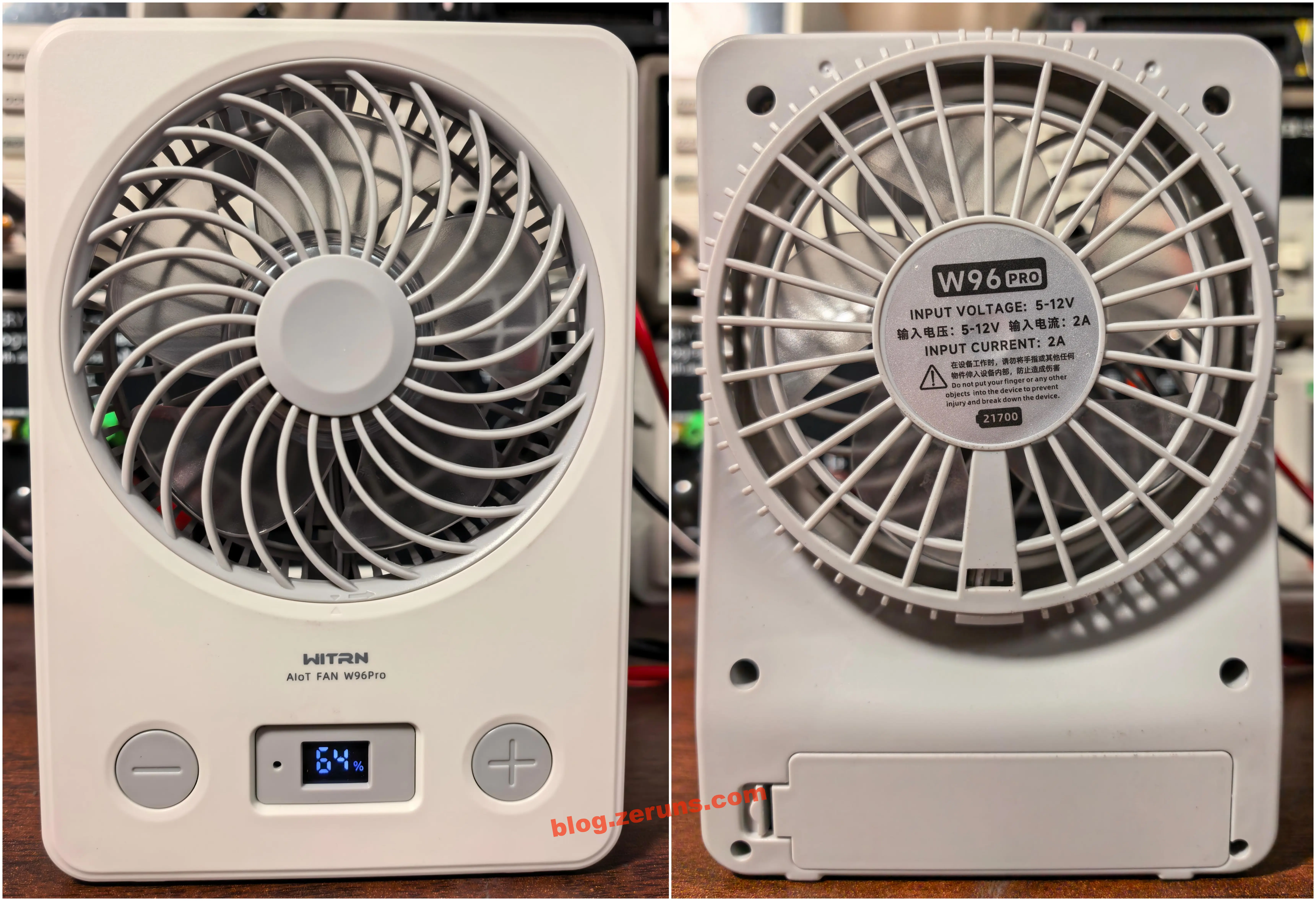
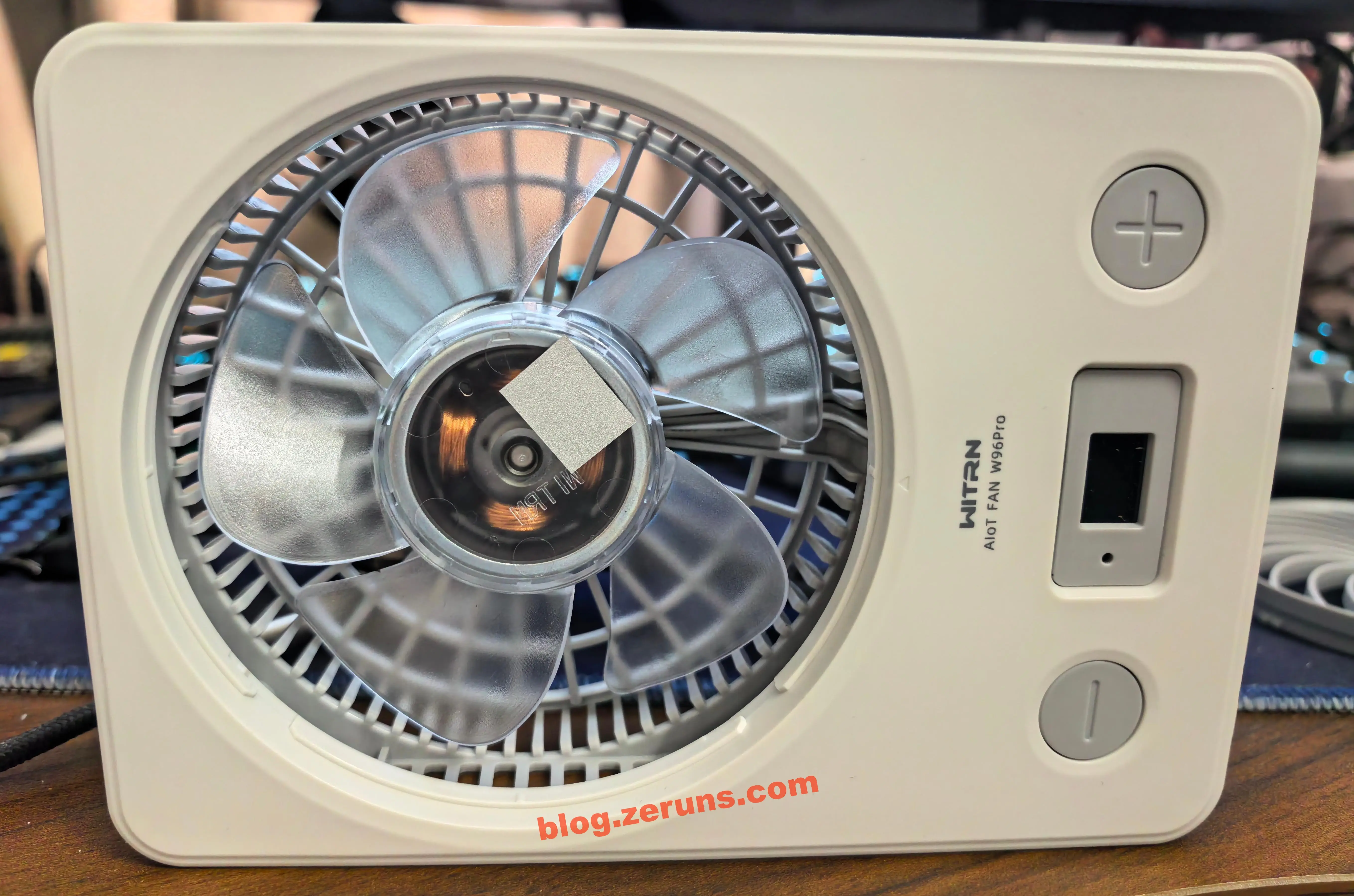
Front and rear views of the fan. There are two buttons on the front:
- The left button is the - key: when the screen is off, a short press displays the battery percentage, then displays gear 0; when the fan is running, a short press lowers the gear; a long press decreases the gear in 1% increments; when the fan is running, a double press sets the auto-off timer, and double-pressing again switches the timer duration.
- The right button is the + key: when the screen is off, a short press turns the fan on and enters gear 1 (10%); the next press raises the gear (the default gears are 10%, 35%, 70%, and 100%, and the percentages for these four gears can be modified with the companion software); a long press increases the gear in 1% increments; a double press enables natural wind mode.
In the middle, there is a Bluetooth connection indicator light (blue) and a digital tube display (white). The digital tube display has three digits; the leftmost digit can only display the number 1. On the far right of the digital tube display, there is also a lightning bolt icon (green when charging) and a % symbol.
Rear view of the fan. There is a label in the middle with parameters printed in Chinese and English:
- W96 Pro
- INPUT VOLTAGE: 5–12 V
- 输入电压: 5–12 V 输入电流: 2 A
- INPUT CURRENT: 2 A
- 在设备工作时,请勿将手指或其他任何物件伸入设备内部,防止造成伤害
- Do not put your finger or any other objects into the device to prevent injury and break down the device.
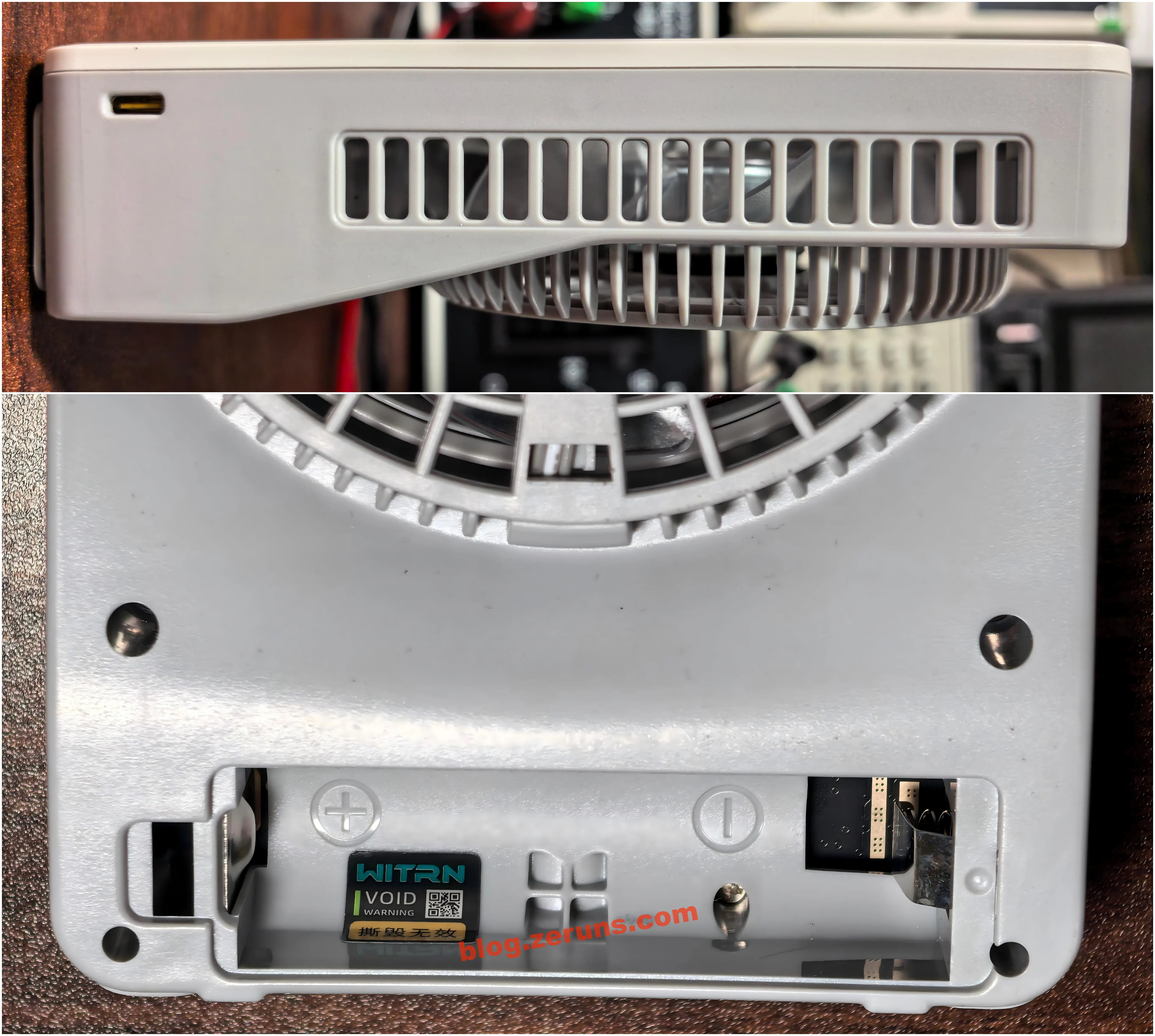
The bottom of the rear is the battery compartment, which supports ternary lithium batteries in the 21700 form factor.

There is a Type-C charging port on the right side of the fan. This USB-C port is bidirectional, so the fan can also be used as a power bank. There is an anti-tamper label over the screw hole in the battery compartment, with the words “void if torn.”

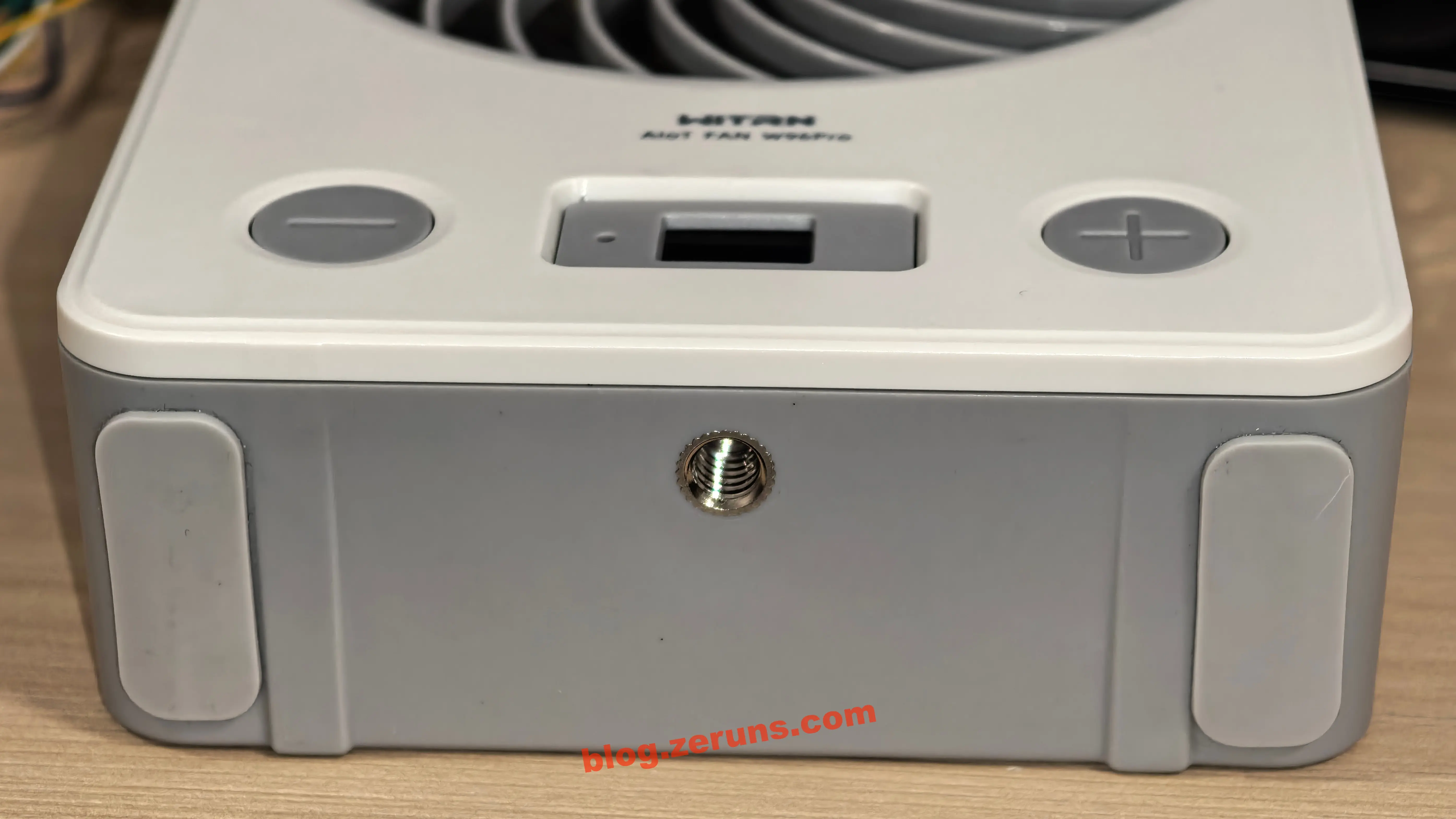
The bottom of the fan also has a 1/4-inch threaded interface, which allows the fan to be fixed to a tripod. The fan also comes with two anti-slip pads (the seller includes two anti-slip pads with the fan; you attach them yourself. I attached them to the bottom).
When running at full speed, the fan is unstable when standing upright and will tip over. If you do not use a tripod, it is recommended to attach the anti-slip pads to the side of the fan and place it on its side.

Charging Power and Heat Test
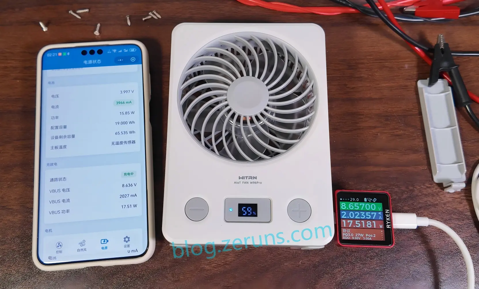
The charger is a 65 W fast charger that supports the PD fast-charging protocol. The fan battery was at 59%, and the measured charging power was about 17.5 W, requesting 9 V.

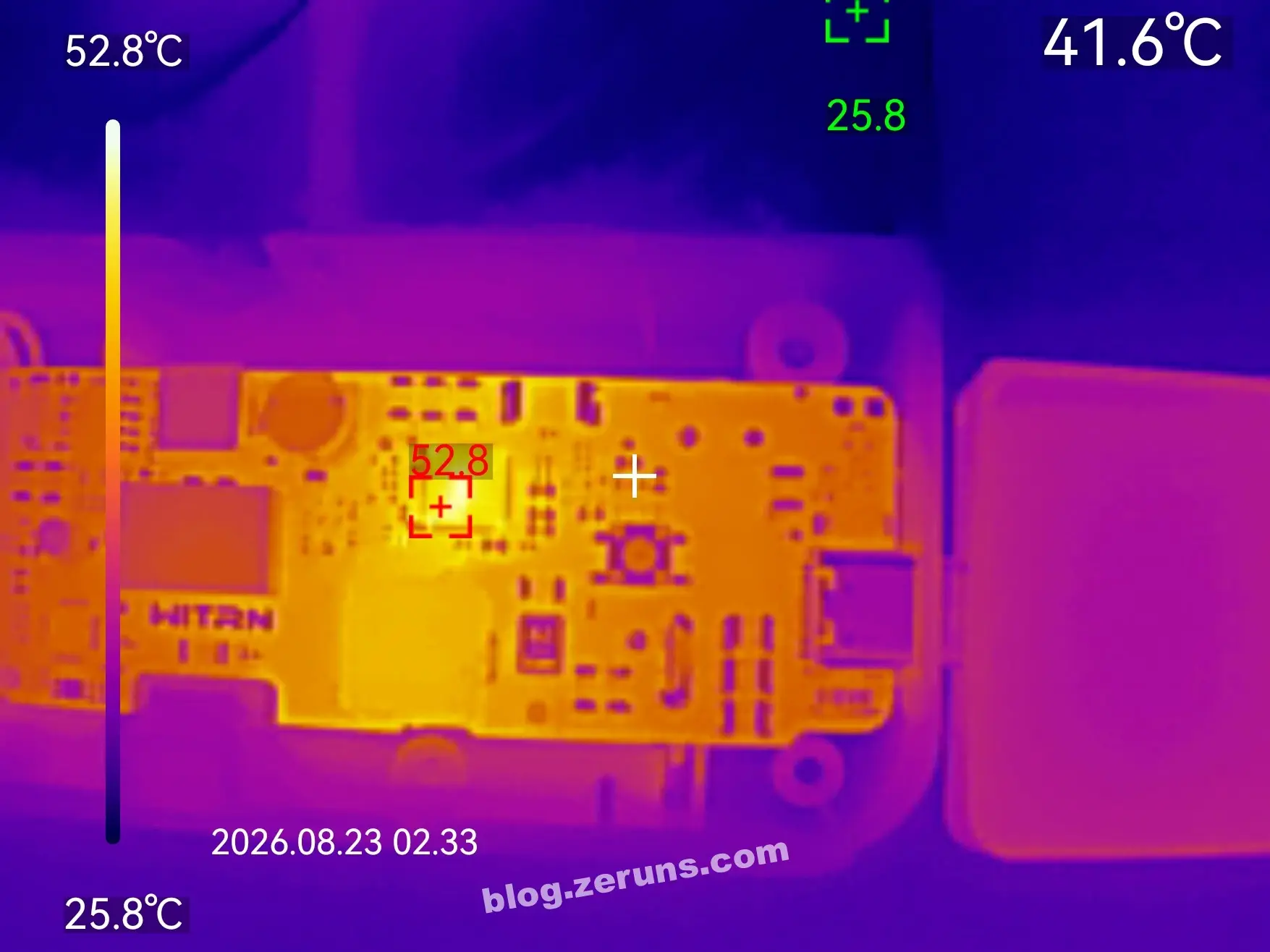
The thermal image below shows the front of the circuit board after ten minutes of charging. The ambient temperature was about 26 °C, and the charging chip temperature was about 52.8 °C.

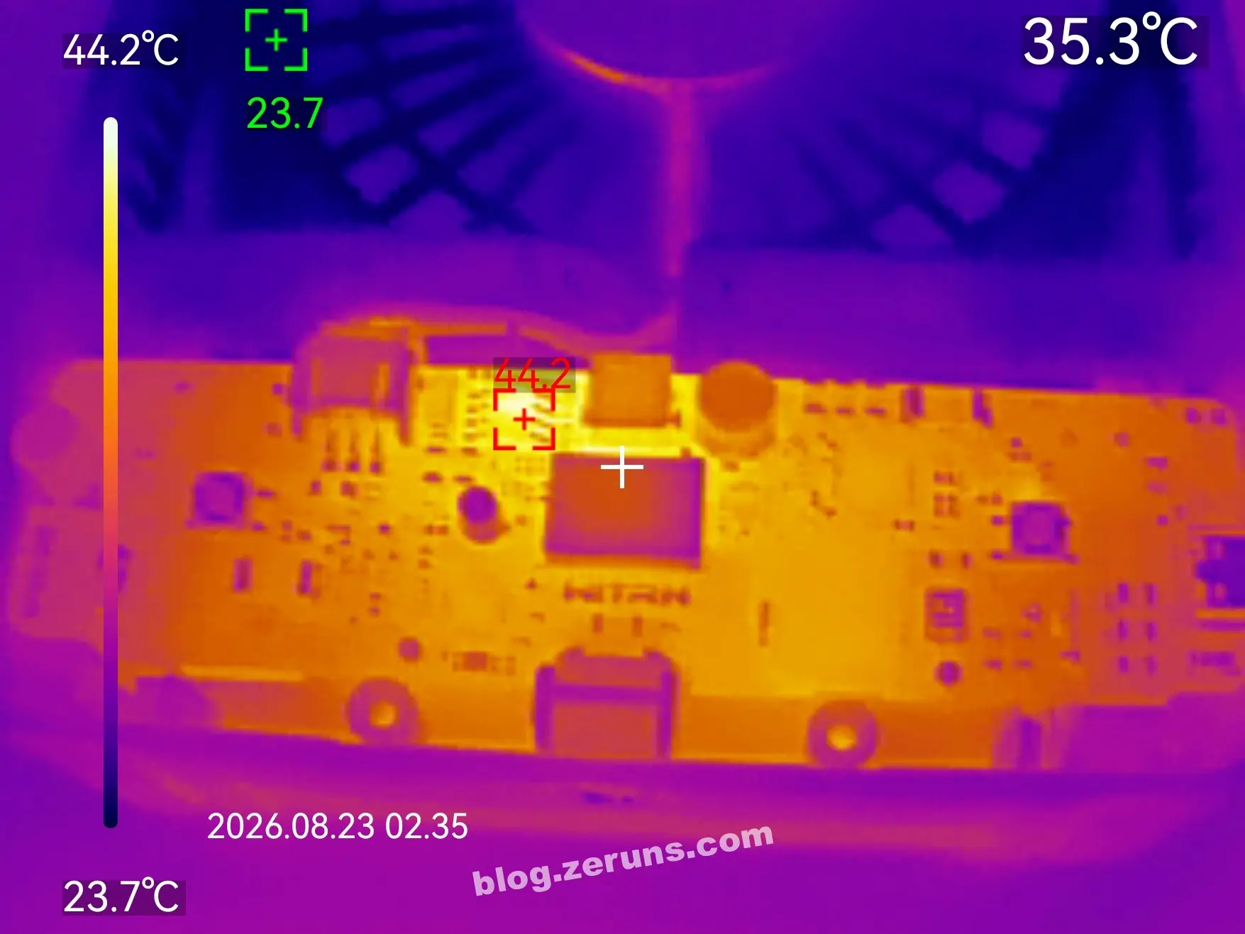
The thermal image below shows the front of the circuit board after the fan ran at the 100% gear for ten minutes. The ambient temperature was about 26 °C, and the boost chip supplying power to the motor was about 44.2 °C.

Speed Test
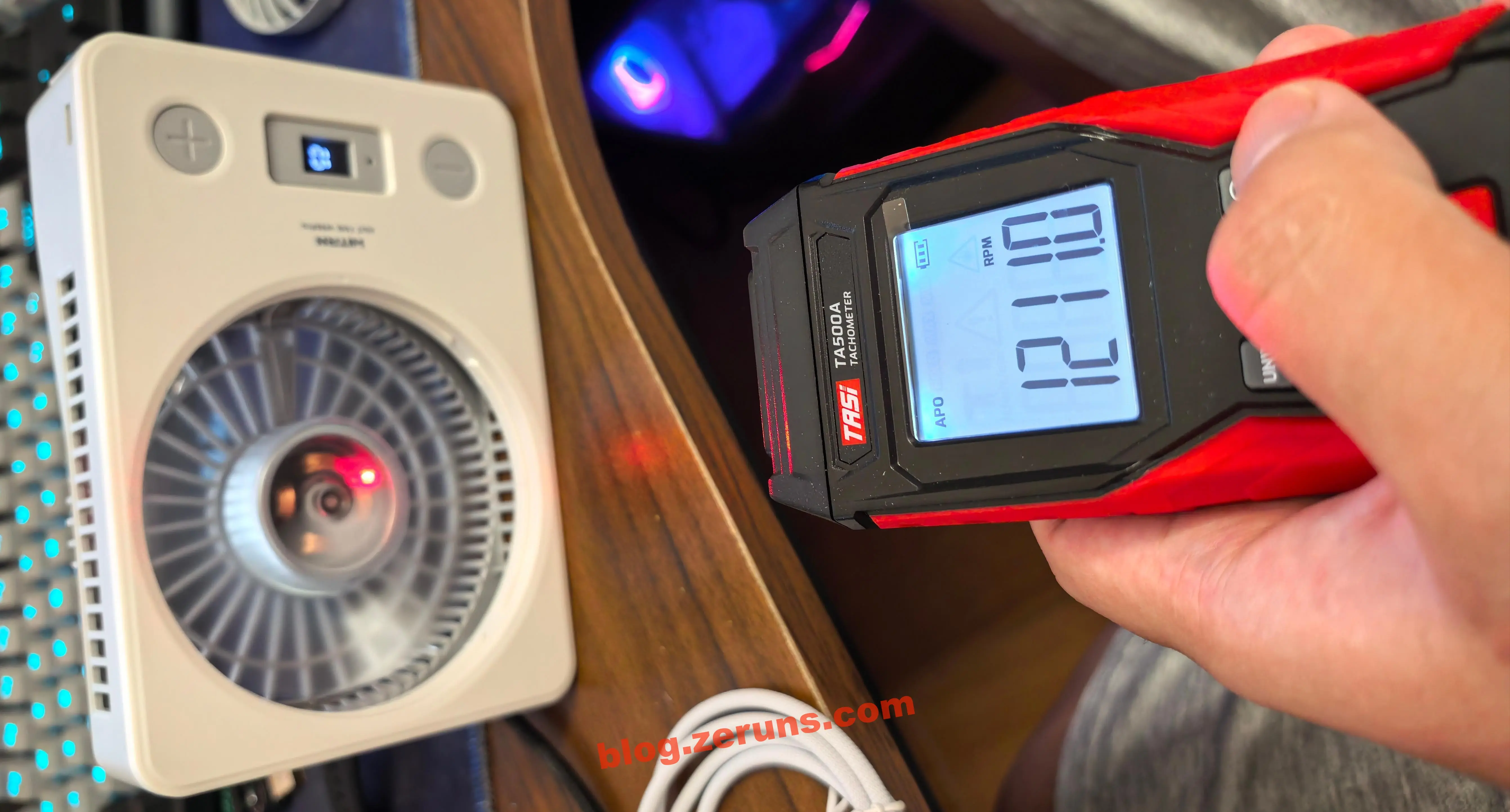
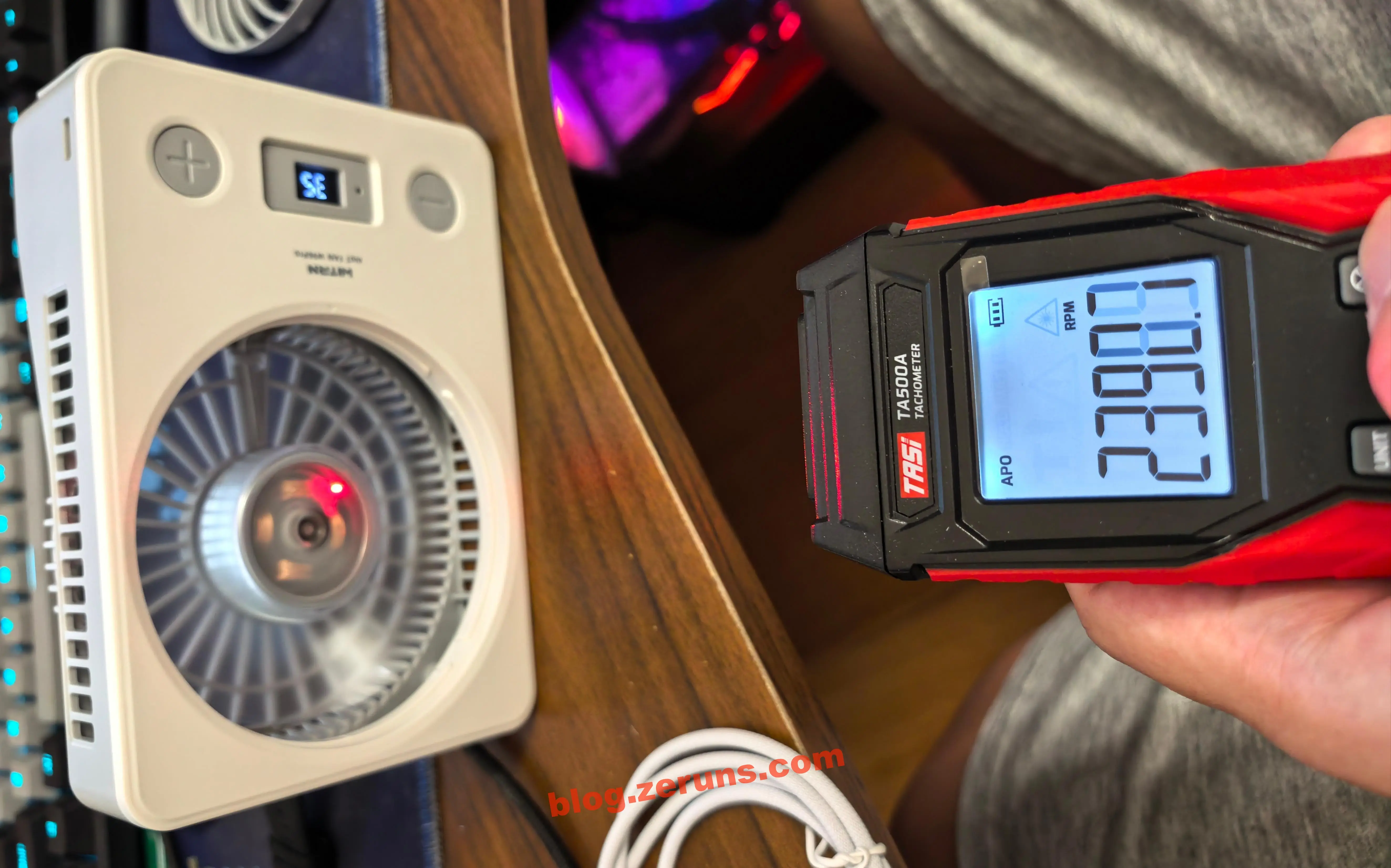
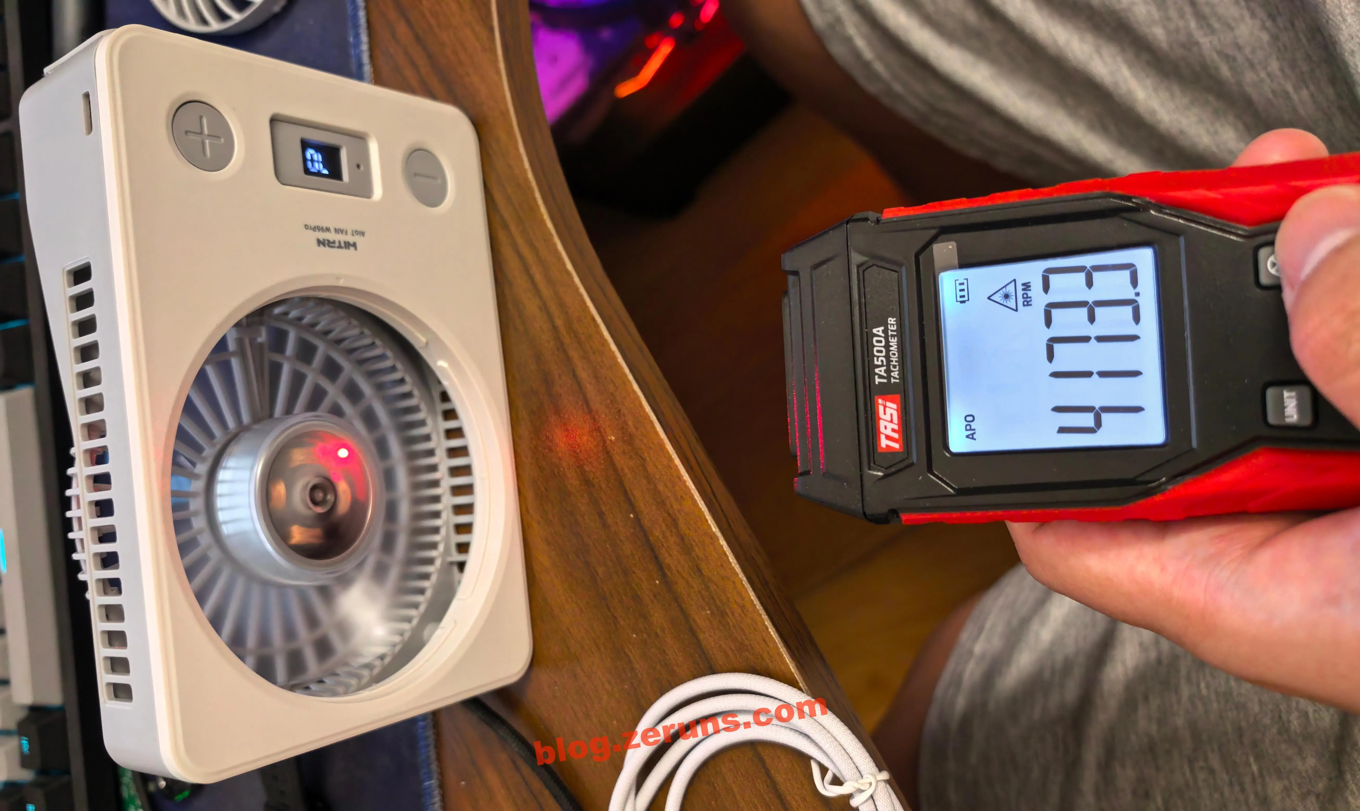
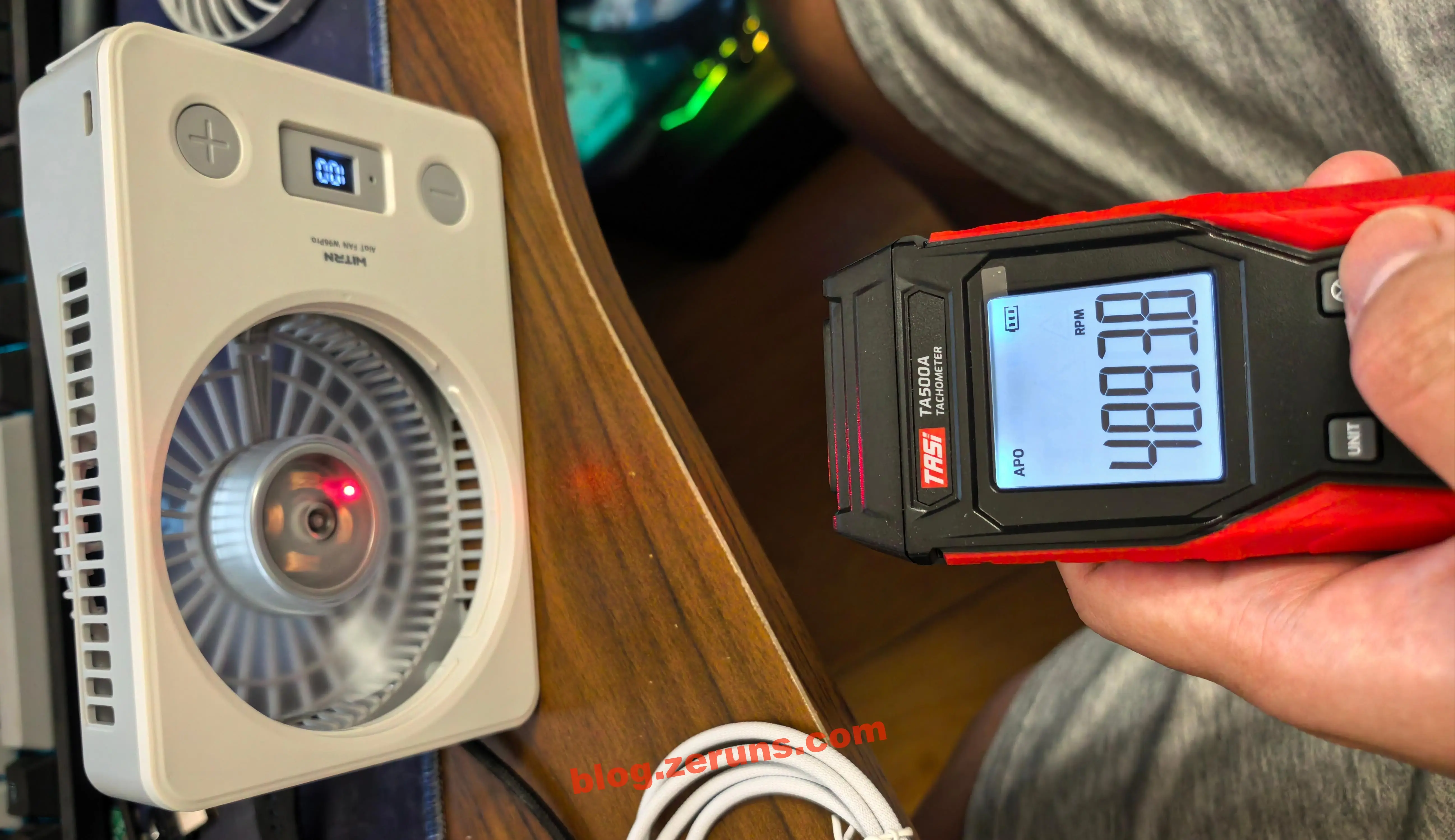
Use the Tians TA500A laser tachometer to test the fan speed. First, attach reflective tape to the fan blades.

Gear 1, 10% speed: 1211 RPM. (RPM: revolutions per minute)

Gear 2, 35% speed: 2390 rpm.

Gear 3, 70% speed: 4173 rpm.

Gear 4, 100% speed: 4893 rpm.

Motor Power Test
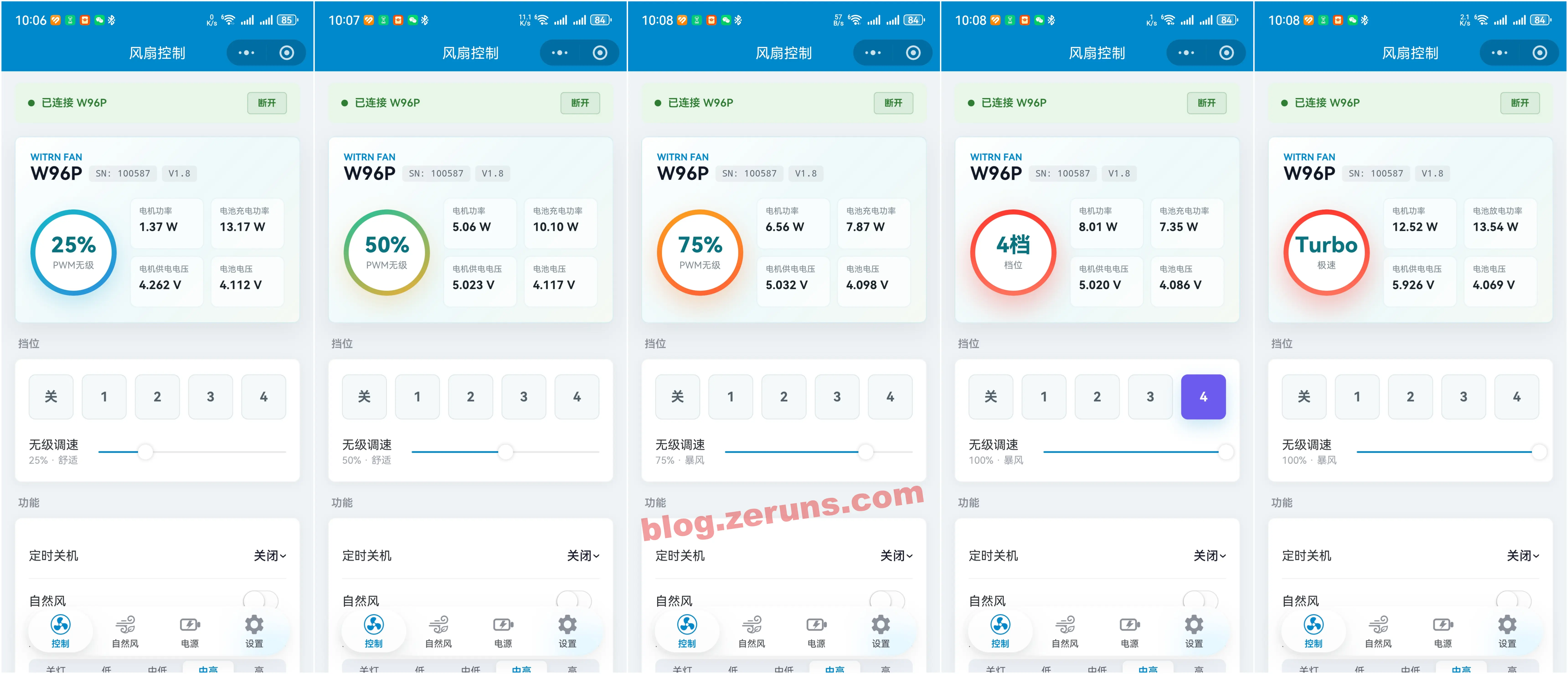
The data in the table below comes from the companion mini program, which connects to the fan via Bluetooth. (I measured the voltage across the fan motor current-sense resistor using a multimeter on the millivolt range, then divided by the resistance value to calculate the current. The result was close to the value obtained from the mini program. The motor voltage was also measured with a multimeter and was close to the value shown in the mini program, so I directly used the values from the mini program.)
| Gear | Motor Power | Motor Voltage |
|---|---|---|
| 25% | 1.37 W | 4.26 V |
| 50% | 5.06 W | 5.00 V |
| 75% | 6.56 W | 5.00 V |
| 100% | 8.01 W | 5.00 V |
| Turbo | 12.52 W | 5.90 V |
The motor is powered by a boost DC/DC converter. Below the 50% gear, the motor supply is 4.2 V; at 50% and above, the motor supply is 5 V; in Turbo mode, it is 5.9 V.

Fast-Charging Output Test
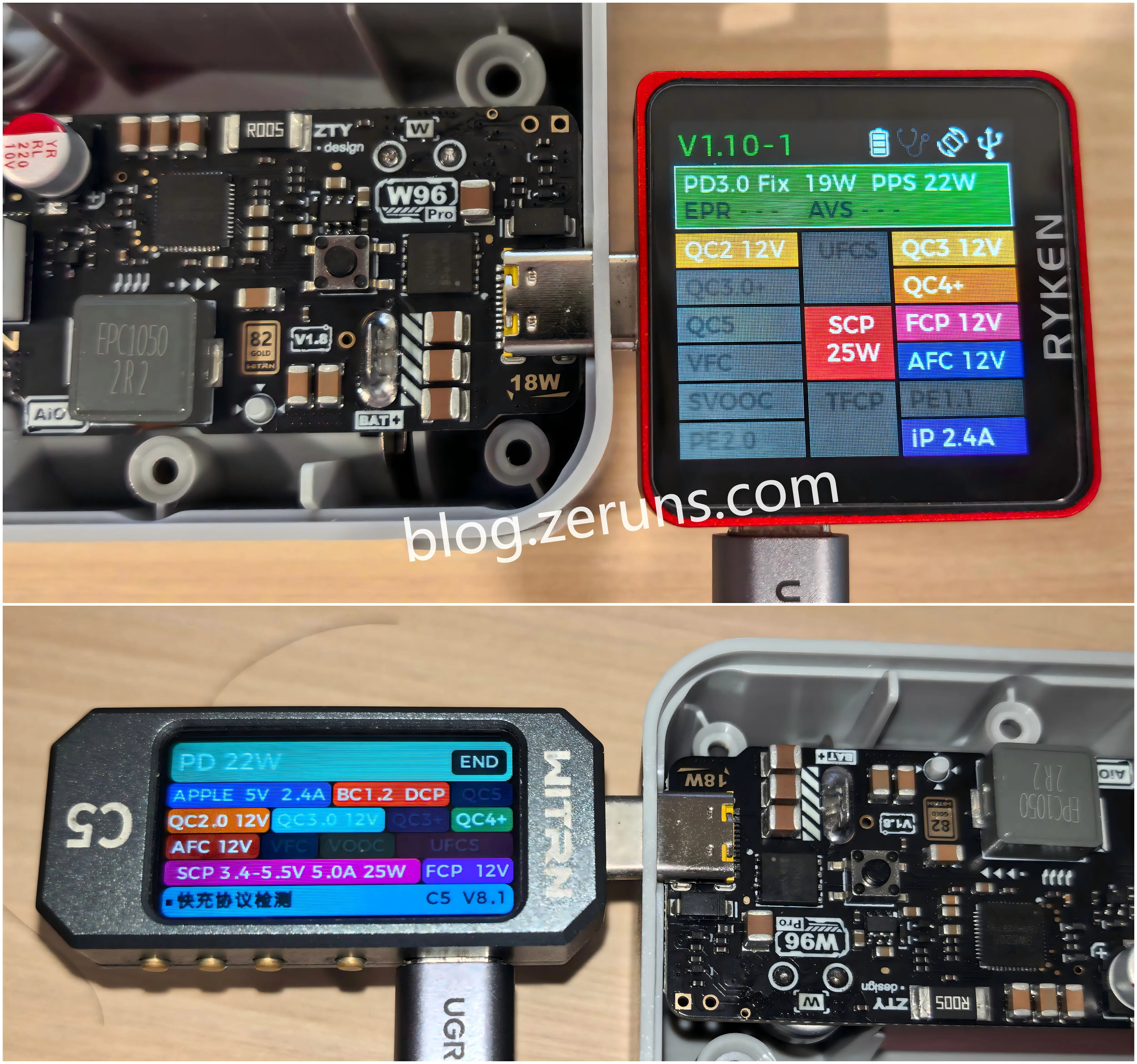
Below, I used the RK-X3 Pro fast-charging tester and the WITRN C5 detector to test which fast-charging protocols the fan’s USB-C port supports for output. It supports PD 22 W, SCP 25 W, QC, FCP, AFC, and other protocols.

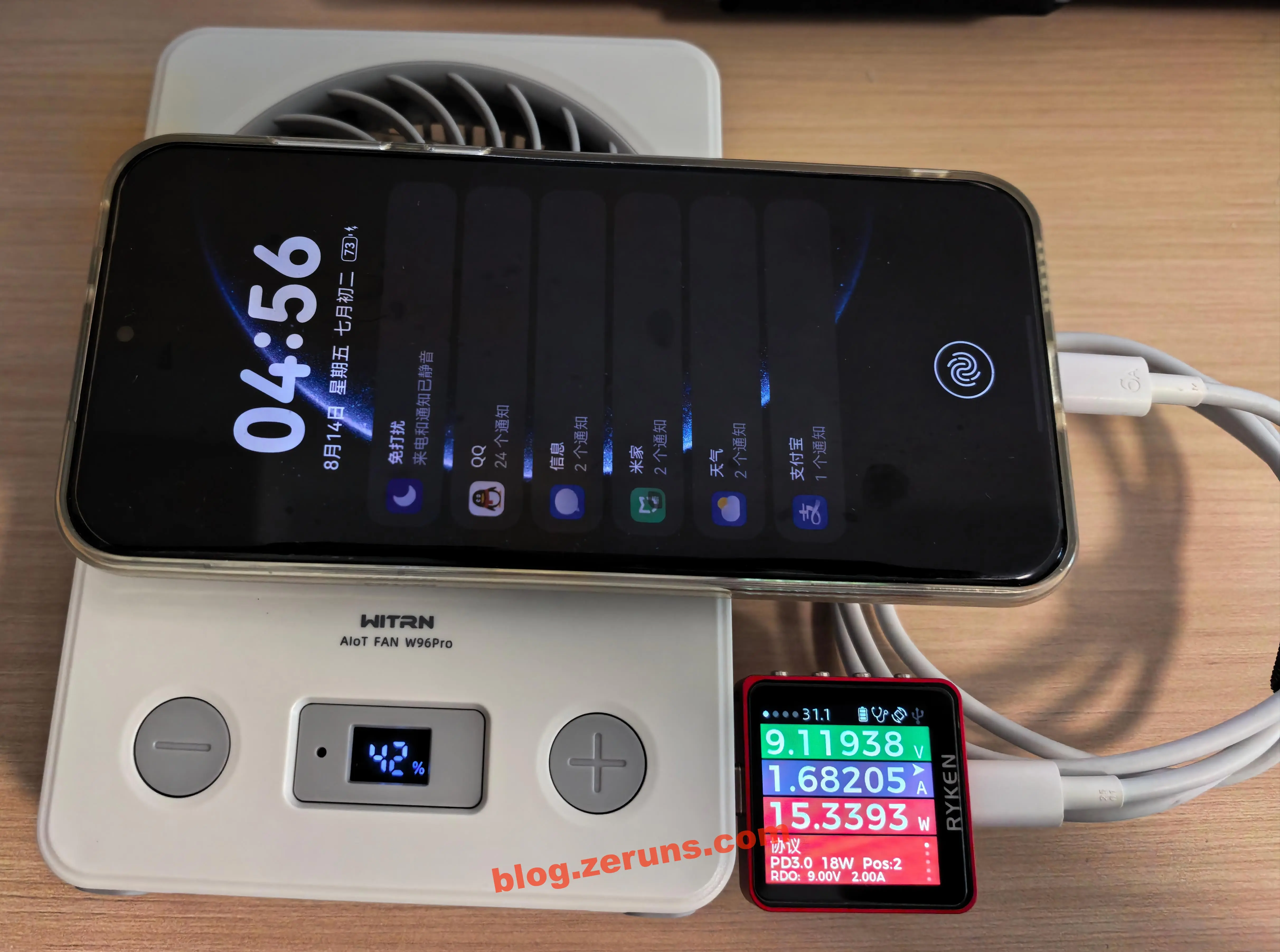
The fan’s USB-C port was used to charge a Huawei Pura 70 Pro+. The charging power was about 15 W, requesting PD 3.0 18 W at 9 V.

Companion Mini Program
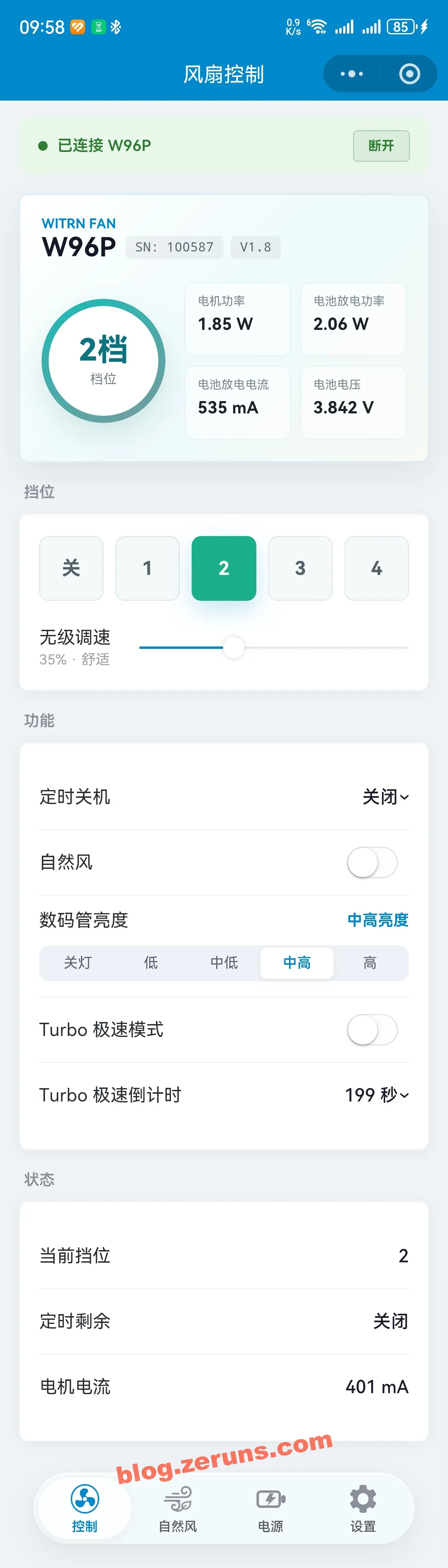
The companion mini program has four pages: Control, Natural Wind, Power, and Settings.
The card at the top of the Control page lets you set four display parameters. The data that can be selected for display includes PWM, auto-off timer, battery percentage, battery voltage, battery current, battery power, configured battery capacity, motherboard temperature (this model does not seem to support it; the temperature data shows 0), charge/discharge status, VBUS voltage, VBUS current, VBUS power, charging chip temperature, motor current, motor supply voltage, motor power, motor status, and so on.
You can control the fan gear or adjust the fan gear by percentage. You can also set the auto-off timer, digital tube display brightness, and more.

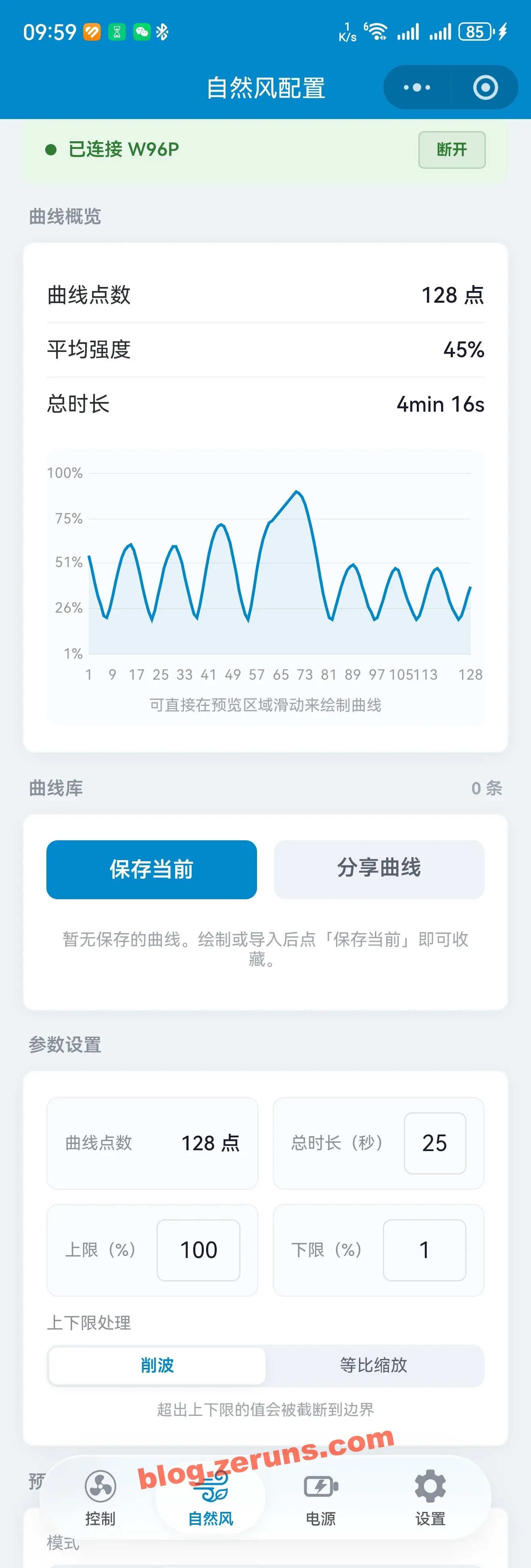
The Natural Wind configuration page lets you set the curve for natural wind mode.

The Power Status page displays various power-related information, such as voltage, current, and power. You can configure the battery capacity (used by the coulomb counter to calculate the remaining battery percentage), and set fast-charging-related options (some fast-charging protocols can be enabled or disabled, and the requested or output voltage for fast-charging protocols can be set).
Note: There seems to be a bug in the firmware or companion mini program. When the new device first arrived, the fast-charging output had a compatibility issue. In my tests, the only devices I had on hand that could trigger fast charging were the Huawei Mate70Pro+ and Pura70Pro+. The vivo X100 and many other devices could not trigger this fan’s charging output, and using a Weijian CC meter to probe fast-charging protocol support yielded no results. Even after going to the fast-charging configuration section on the mini program’s power page and enabling all compatibility modes, the issue remained. However, after switching to Expert Mode, finding Type-C Role, and changing Only Sink to DRP, everything returned to normal, and the fast-charging protocols could be detected properly again.

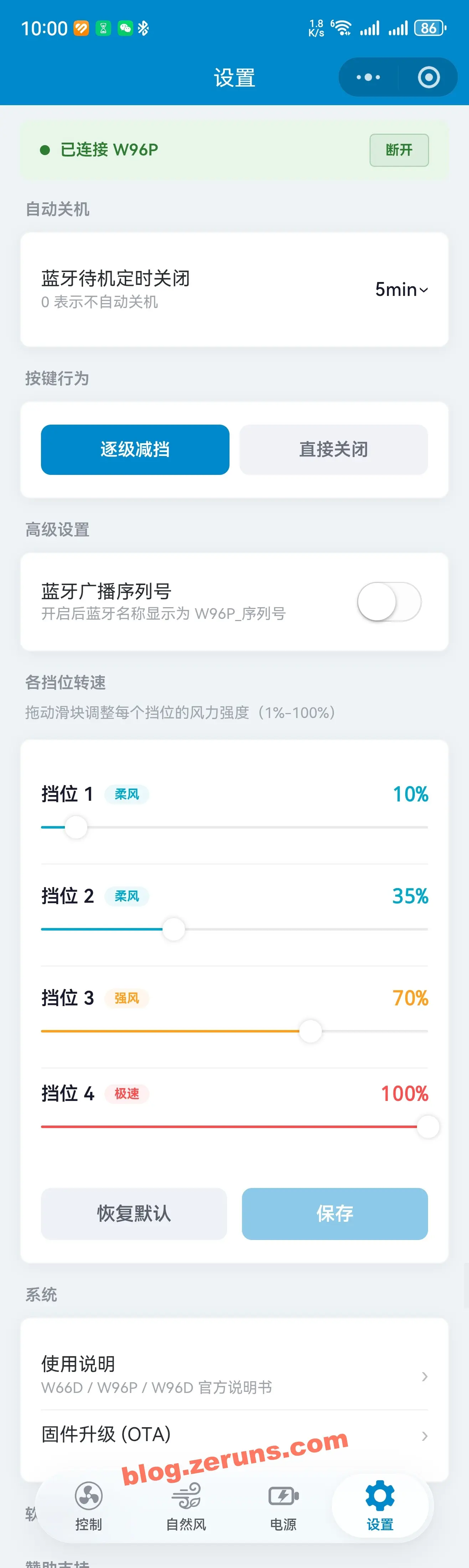
Settings page, where you can set the speed percentage for each gear and upgrade the firmware.

Teardown
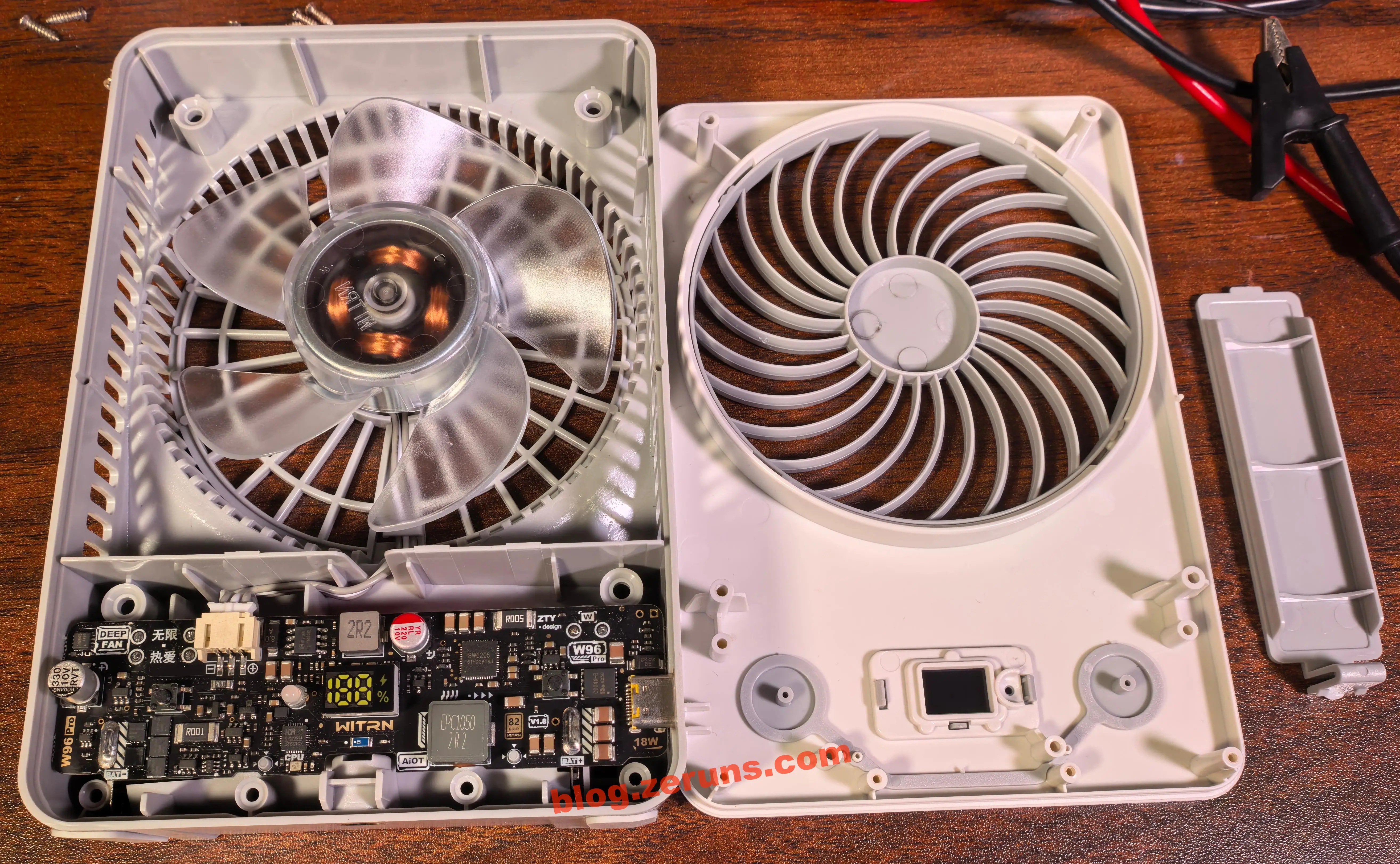
Unscrew the 6 Phillips screws on the back of the fan, 4 on the outside and 2 in the battery compartment, one of the screw holes in the battery compartment has an anti-tamper label, and then remove the front panel of the fan. The motor has 4 sets of stator coils and is probably a two-phase BLDC (brushless DC motor). It could also be a single-phase BLDC; to know for sure, the rotor would need to be removed and the motor driver board and coil winding traces checked. The wires from the main board to the motor are 3P.

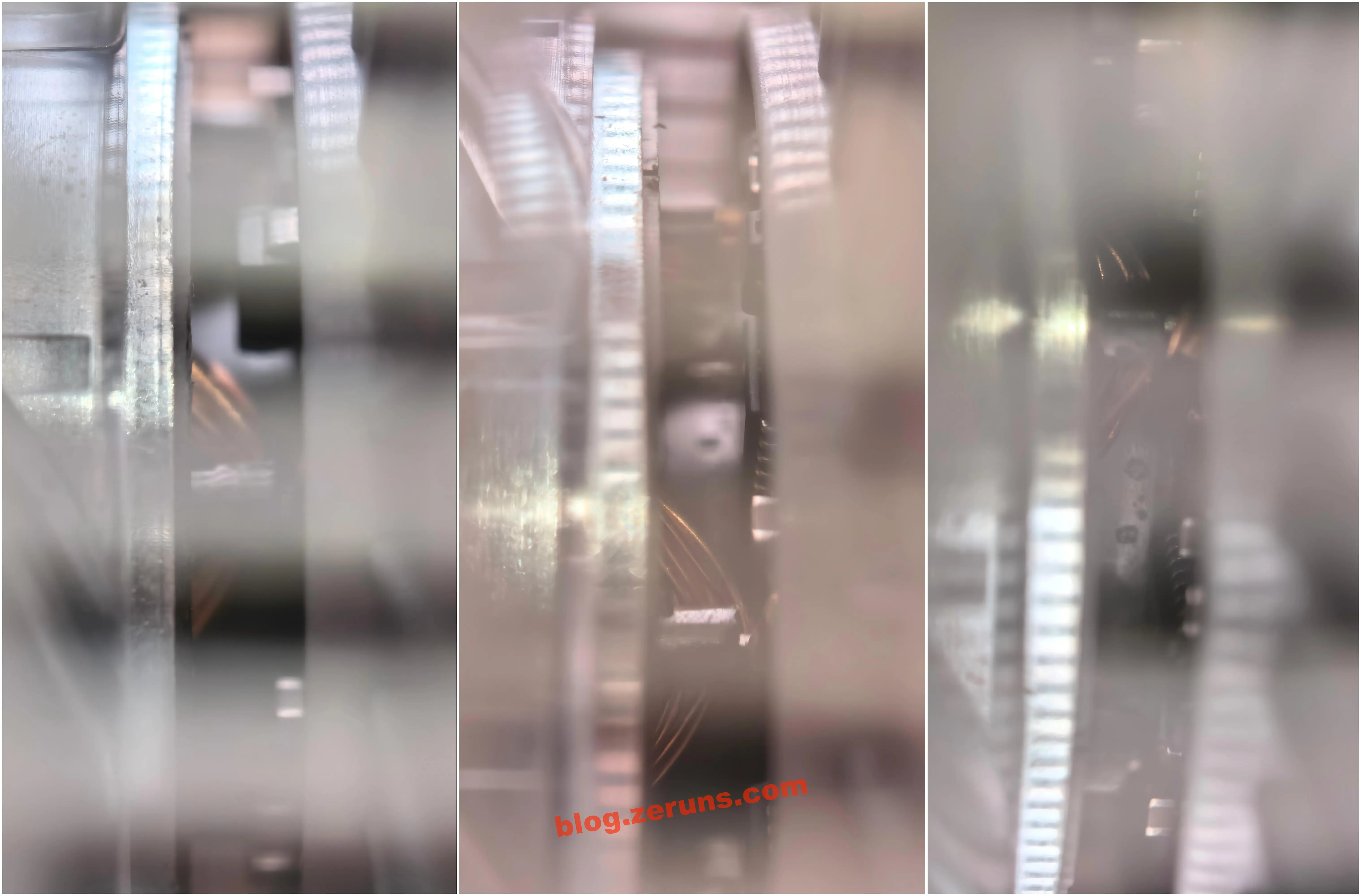
From the side of the motor, it can be seen that the underside of this motor includes drive circuitry. This motor, like the brushless motors in cooling fans, has its own drive circuit, but strictly speaking, the drive method is different: most ordinary cooling fans use square-wave/trapezoidal-wave six-step commutation, while this one is advertised as using sinusoidal drive, which is a higher tier. This unit has 4 sets of coils. The official marketing describes it as a “sinusoidal DC brushless motor,” meaning the drive waveform uses a sine wave, i.e. SPWM modulation. To verify this, the motor would have to be removed and the phase current waveform measured with an oscilloscope.
(There is a contradiction here: sinusoidal drive is generally used in three-phase motors, and the coil count in three-phase motors is always a multiple of 3. This one has only 4 coils, which is closer to a two-phase or single-phase four-pole motor. However, a two-phase motor can also be driven by two sine waves 90° apart and achieve smooth torque in the same way, so “4 coils + sinusoidal drive” is not impossible. What phase it actually is and whether it is truly sinusoidal both need to be confirmed by measuring the waveform with an oscilloscope. But since I still need to keep using this fan, I will not continue disassembling the motor.)
Advantages of sinusoidal DC brushless motors compared with other ordinary brushless motors:
- Smoother torque and less vibration: sinusoidal current is in phase with the back EMF, so torque is continuous without steps and operation is more stable
- Lower noise: there are no high-frequency current jumps or harmonics from square-wave commutation, so electromagnetic noise is significantly reduced — the most important point for portable fans
- Higher efficiency and less heat: harmonic losses are reduced, so temperature rise is lower at the same output power
- Better low-speed performance: low gears run stably without jitter, making them suitable for quiet operation
- Finer speed control: combined with PWM + boost voltage regulation, it can achieve near-stepless speed adjustment
- Tradeoff: the drive algorithm is more complex and the driver board costs more

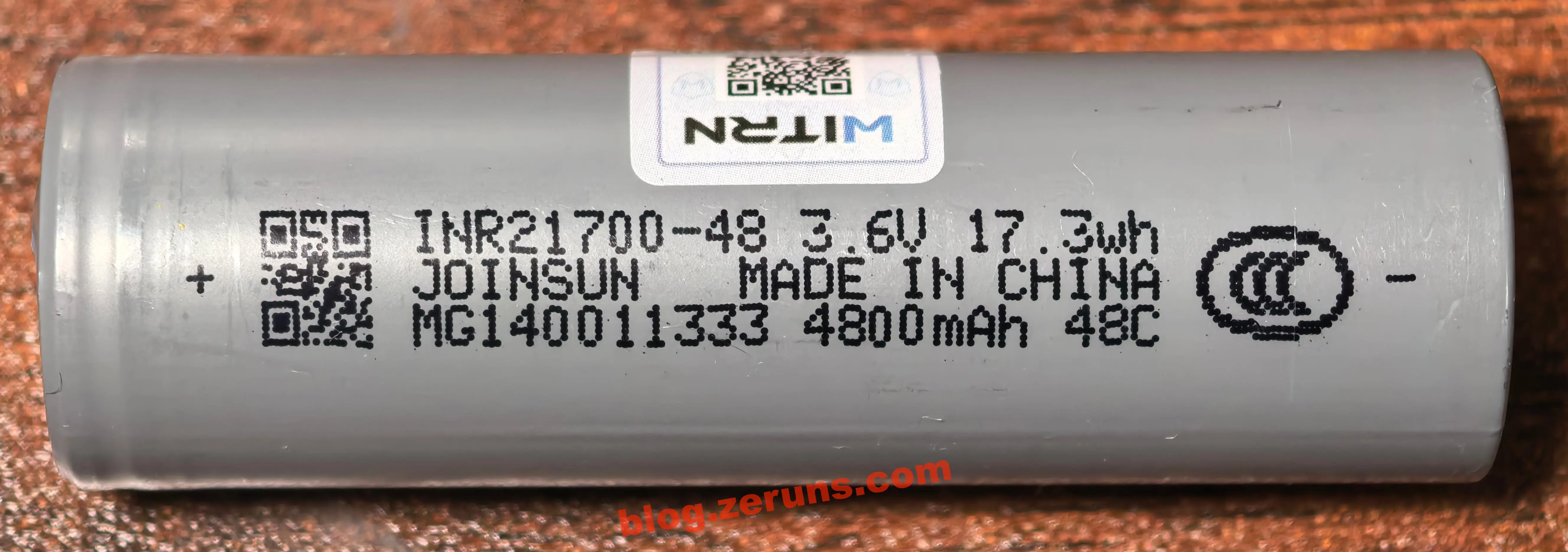
The matching battery is a JOINSUN INR21700-48 cylindrical ternary lithium-ion cell from Jixin Technology, model 48C (digital/energy-storage type). Its nominal capacity is 4800mAh, nominal voltage is 3.6V, energy is 17.3Wh, and its size is 21700 specification, about 21mm in diameter and 70mm high, measured at 21.7×70.8mm. The casing is printed with the China Compulsory Certification (CCC/3C) mark.
Core specifications for JOINSUN INR21700-48C (checked against datasheet/official website):
- Cathode material: pure ternary NCM 811 (NMC) — ternary lithium
- Capacity: nominal 4800mAh, minimum 4700mAh; nominal voltage 3.6V, energy 17.28Wh (≈17.3Wh)
- Charging specification: maximum charging voltage 4.2V, charging current 0.5C (2.4A), maximum 1C; discharge cutoff 2.5V
- Discharge rate (48C digital type): continuous 2C (9.6A), maximum pulse 4C (about 19.2A)
- Internal resistance: ≤22mΩ; weight: about 69~71g
- Cycle life: at 80% DoD and 25℃, ≥400 cycles at 2C discharge and ≥500 cycles at 1C discharge
- Certifications: UL / FCC / CE / RoHS / IEC / CB / CCC (3C) / PSE / UN38.3 / MSDS
- Application positioning: the official website explicitly lists it for portable fans, power banks, small appliances, electric toothbrushes/fascia guns, and other 3C digital products

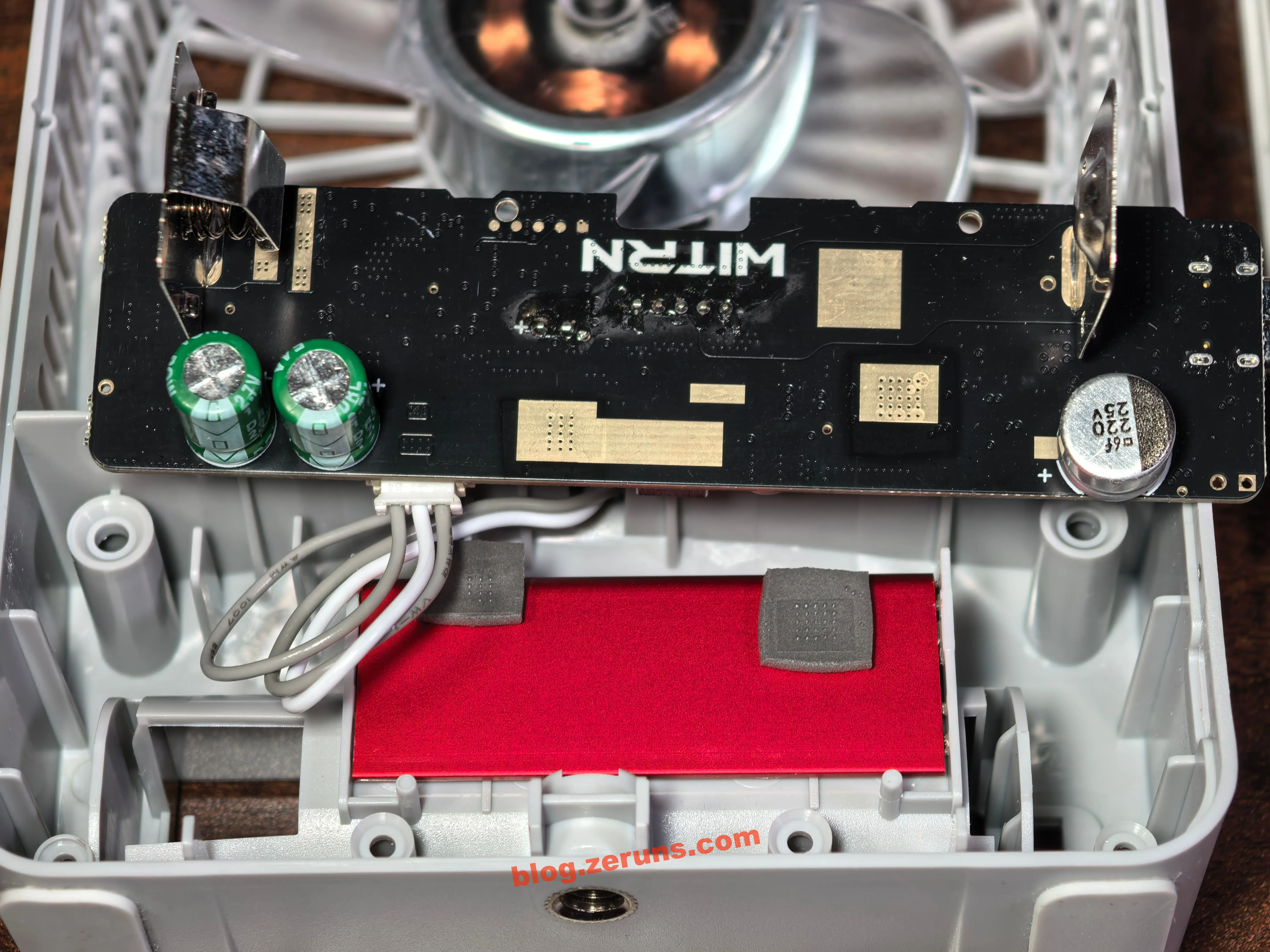
After removing the main board, you can see through-hole battery holder contact tabs soldered to the back of the board. The middle of the PCB has the silkscreen marking WITRN, and there are several solder-mask opening areas on the PCB for heat dissipation from the fast-charging chip and boost chip.
The board uses ENIG plating, which costs more than HASL. Its advantages are good surface flatness, oxidation resistance, corrosion resistance, and chemically stable gold plating, so it is less likely than HASL to oxidize during storage and affect solderability. It also has a longer shelf life, higher soldering yield, and better contact reliability.
There is also a 220μF/25V solid-state capacitor on the lower-right side of the board, connected in parallel on the C-port input side, used for energy storage and filtering.
Under the battery compartment area, there is an aluminum plate used for heat dissipation. Two thermal pads are attached to the aluminum plate, corresponding to the fast-charging chip and boost chip areas on the circuit board, spreading the chips’ heat across the entire plate.
There is flux residue around the through-hole pads for the seven-segment display and LEDs. The through-hole components on this board were likely manually soldered afterward, and the flux residue was not cleaned.
Residual flux can potentially cause: after absorbing moisture in humid environments, surface insulation resistance decreases, causing leakage current between adjacent pads; if the flux contains active ingredients such as halogens/organic acids, long-term residue may also corrode solder joints and copper foil; in extreme cases, under the combined effects of bias voltage and moisture, electrochemical migration (ECM) can occur, where metal dendrites grow between pads and eventually cause short circuits. In addition, sticky residues can easily attract dust, further increasing the risk of leakage.
However, two points should be noted objectively. First, mass-produced boards generally use no-clean flux, whose residue is inert and basically non-conductive, so not cleaning after soldering is a standard industry practice and not a process defect. Second, these two residues are located near the seven-segment display and LED driver pads, where signal voltages are low and driver impedance is low, so even slight leakage current would not affect operation. Therefore, this residue is mostly a cosmetic issue with very little practical risk; it is a small detail that can be cleaned up if convenient, using PCB cleaner or anhydrous alcohol, but there is no need to be overly critical of it.

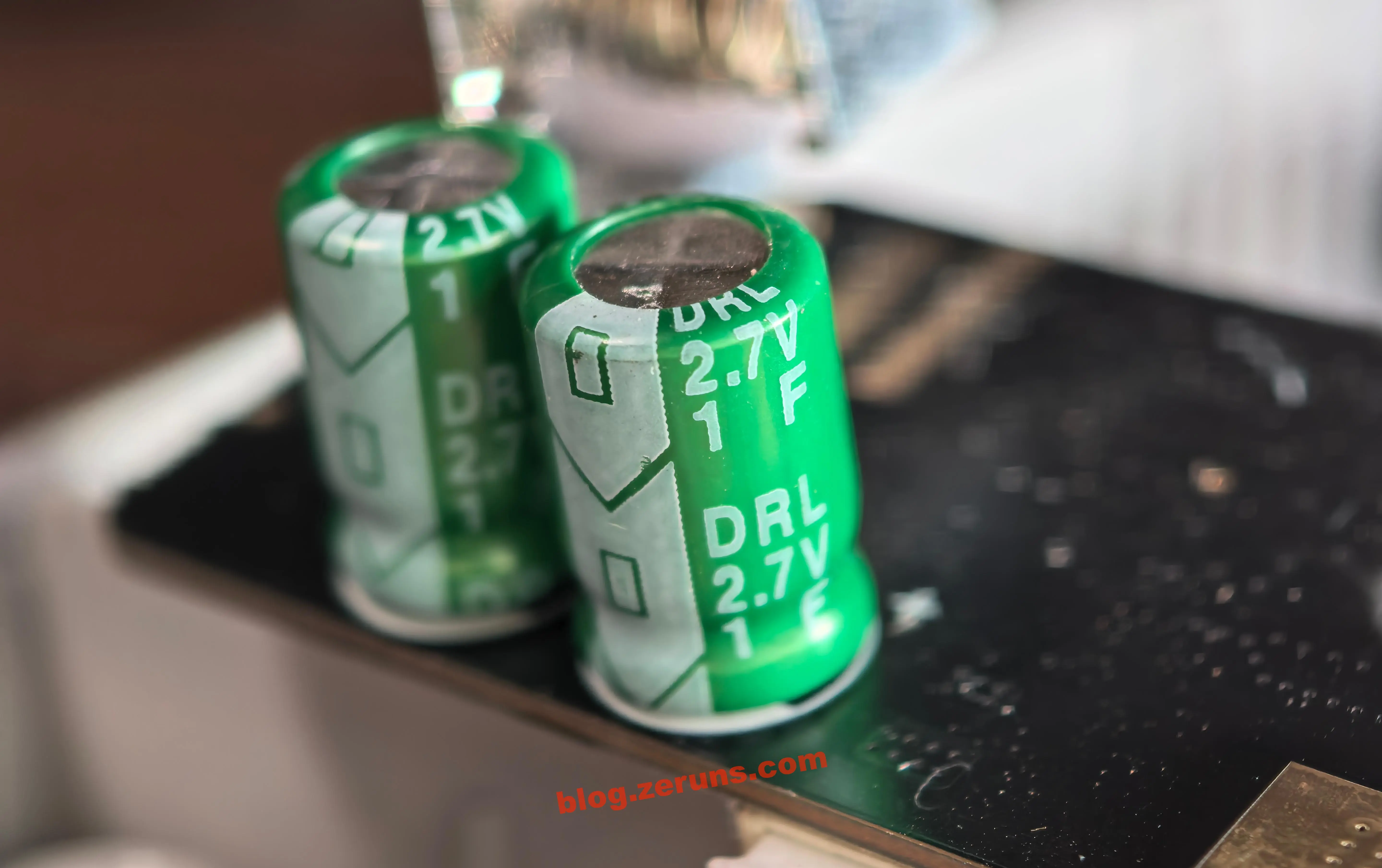
On the left side of the back of the main board, there are two 1F/2.7V supercapacitors connected in series and then in parallel across the battery.

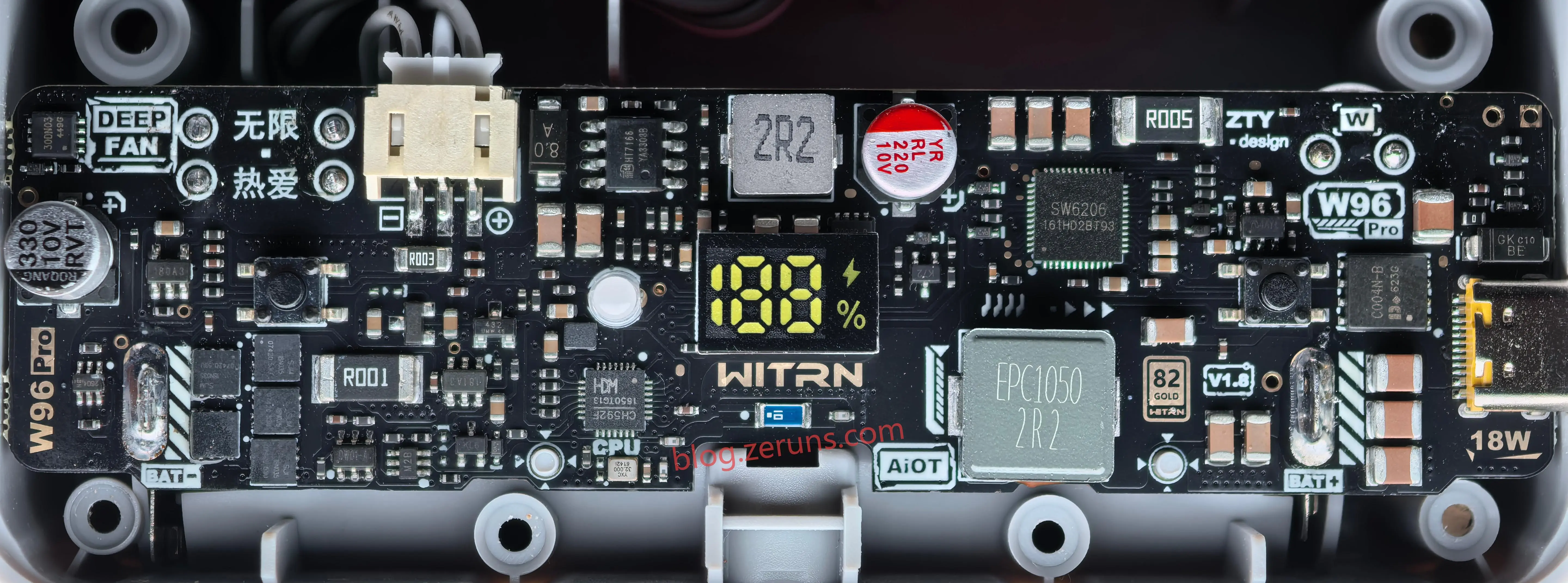
On the front of the main board, the model W96 Pro is printed in the upper-right corner, and the version number V1.8 is printed in the lower-right. Below the Type-C connector, 18W is marked in a solder-mask opening. In the middle of the board is the seven-segment display, and WITRN is marked below it in a solder-mask opening. The blue component further below is likely a chip ceramic antenna, used as the Bluetooth antenna for the main controller.
The fan motor connector is probably PH2.0-3P. From left to right in the image, the wire order is PWM control line, motor power negative, and power positive.

First, let’s look at the charging circuit. The charge power-management chip is SW6206, a multi-protocol bidirectional fast-charging power-bank SoC from Zhuhai ISmartWare. It is not the more common Injoinic IP5353 solution — the SW6206 has a larger package, QFN48 6×6mm, and a higher level of integration. A single chip handles USB-C fast-charging input, high-current lithium-battery charging, and fuel gauging.
Core specifications for SW6206, AI-generated:
- Core functions: multi-protocol bidirectional fast-charging power-bank SoC, integrating 5A high-efficiency switching charge with 96% efficiency, 22.5W synchronous boost output with 95% efficiency, fuel gauge, built-in coulomb counter + 12-bit ADC, LED driver, and Type-C logic, try.SRC
- Charge/discharge: maximum charging current 5A, supports 4.2/4.35/4.4/4.5V batteries, includes NTC/JEITA temperature control, low-temperature current reduction, high-temperature voltage reduction, over-temperature shutdown; actual circuit does not appear to include an NTC resistor; 400kHz switching frequency, only requires a 2.2µH inductor
- Fast-charging protocols: input PD3.0/2.0, AFC, FCP, SCP, PE; output PPS/PD/QC4+/QC3/QC2/AFC/FCP/SCP/PE2/SFCP
- Interface: I2C; external power-MOS gate drivers GATEA/B/C/L
Below the SW6206 is the matching inductor, which together with the MOSFETs built into the charging chip forms a buck-boost circuit. During charging, it operates in Buck step-down mode, and when outputting from the C port, it operates in Boost step-up mode. The inductor model is EPC1050-2R2, an EPC series integrated inductor from Sntengwei in Shenzhen.
Core specifications for EPC1050-2R2:
- Model: STWEPC1050-2R2MT
- Inductance: 2.2μH ±20%
- DC resistance, DCR: 5mΩ
- Rated current, Idc: 22A
- Saturation current, Isat: 30A
The maximum current of this charging circuit is only about 5A, and the inductor used has a rated current of 22A, more than 4 times higher, so the margin is quite generous. The component choice is good.
The 5–12V from USB-C passes through a C004N-B N-channel MOSFET, with its gate connected to the GATEC pin of the SW6206, as a power-path switch, and then enters the charging circuit.
Above the SW6206 there is also a resistor marked R005. This is a 5mΩ current-sense resistor, probably in a 2512 package, used to sample charge/discharge current.
The main controller connects to the SW6206 through an I2C interface, allowing it to read charge/discharge data and configure this power-management chip.

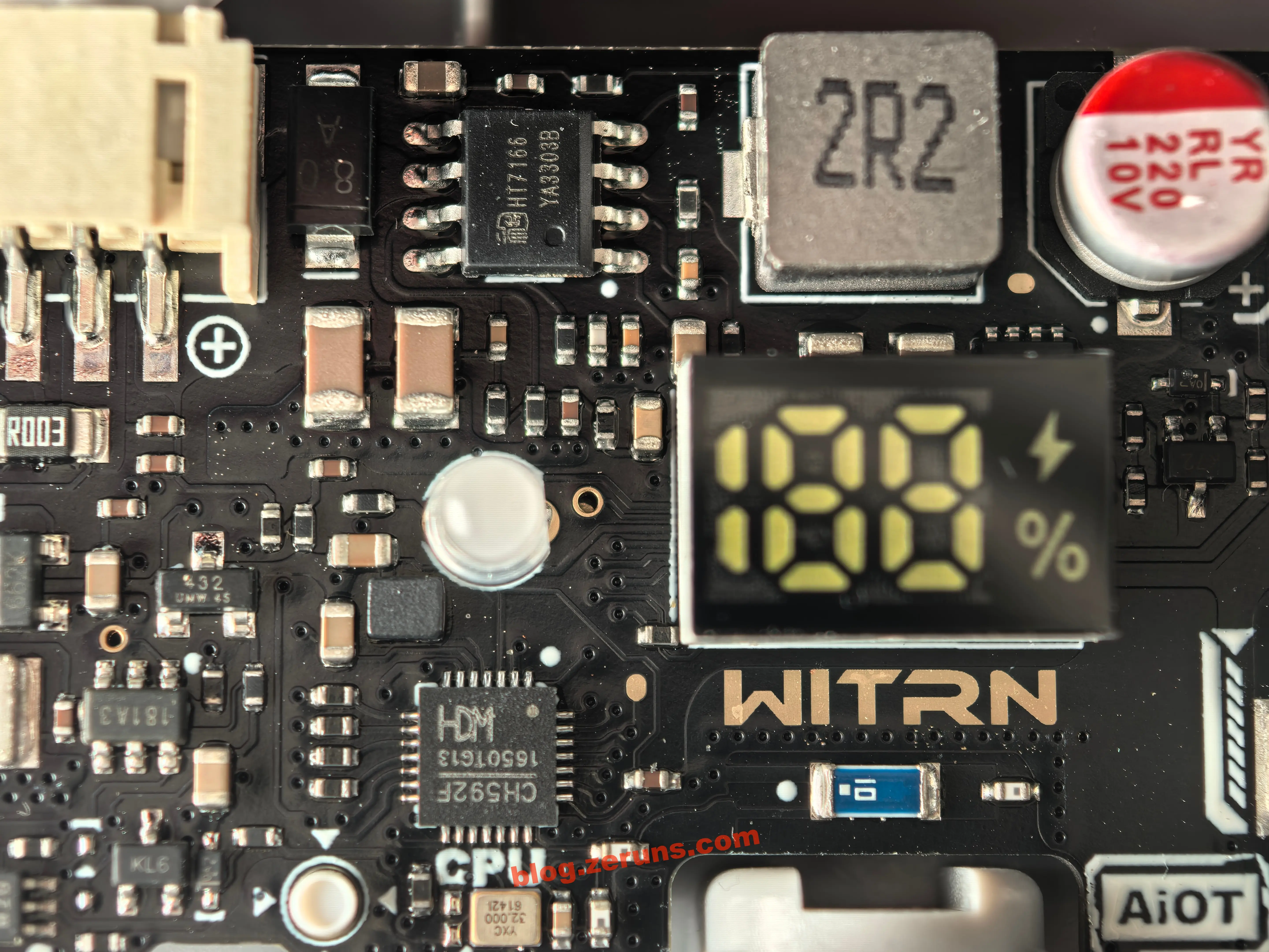
The chip at the lower-left of the seven-segment display is the main-control MCU, model CH592F, a RISC-V-core BLE 5.4 wireless MCU from Nanjing WCH Microelectronics.
Core specifications for CH592F, AI-generated:
- Qingke 32-bit RISC-V4C core, maximum main frequency 80MHz, 512KB Flash, supports OTA wireless upgrades, 26KB SRAM, 20 GPIO
- Integrated 2.4GHz transceiver, BLE 5.4, receive sensitivity −95dBm, programmable +4.5dBm transmit power
- Segmented LCD driver, the digital screen is driven directly by the MCU IO; multiple PWM channels, 12 ADC channels, RTC, USB 2.0
- Built-in DC-DC; sleep current as low as 0.3~2.5µA, corresponding to the official “Bluetooth standby 10 days”
- QFN28 package
What the main controller handles: Bluetooth connection, digital display, gear 0–100/battery %, buttons, natural-wind/timer/Turbo logic, outputting PWM to the motor driver board, reading battery level, and two channels of current/voltage sampling, and so on.
Below the main controller chip is the controller’s clock crystal, a 32MHz passive crystal from YXC.
Above the seven-segment display is the motor power-supply circuit, a Boost step-up circuit. The boost chip model is HT7166. The chip’s output voltage and enable signal are controlled by the main-control MCU. The boost output is supplied directly to the motor. The boost converter is enabled only when the fan is turned on. When the wind speed is set below 50%, the boost output voltage is 4.2V; above 50%, it is 5V; and in Turbo mode, it is 5.9V.
Core specifications for HT7166, AI-generated:
- Heroic 13V/10A fully integrated synchronous boost converter, ESOP-8-PP, built-in 16mΩ power MOSFET + 23mΩ synchronous rectifier, no external power MOS required
- VIN 2.7~13V, switching frequency about 600kHz, soft start 4ms, peak current limit 10A
- EN enable pin: off below 0.4V, operating above 1.5V, shutdown current about 1µA
- Protection: 14.2V output overvoltage, UVLO, VIN 2.4V, thermal shutdown; light-load PFM for efficiency

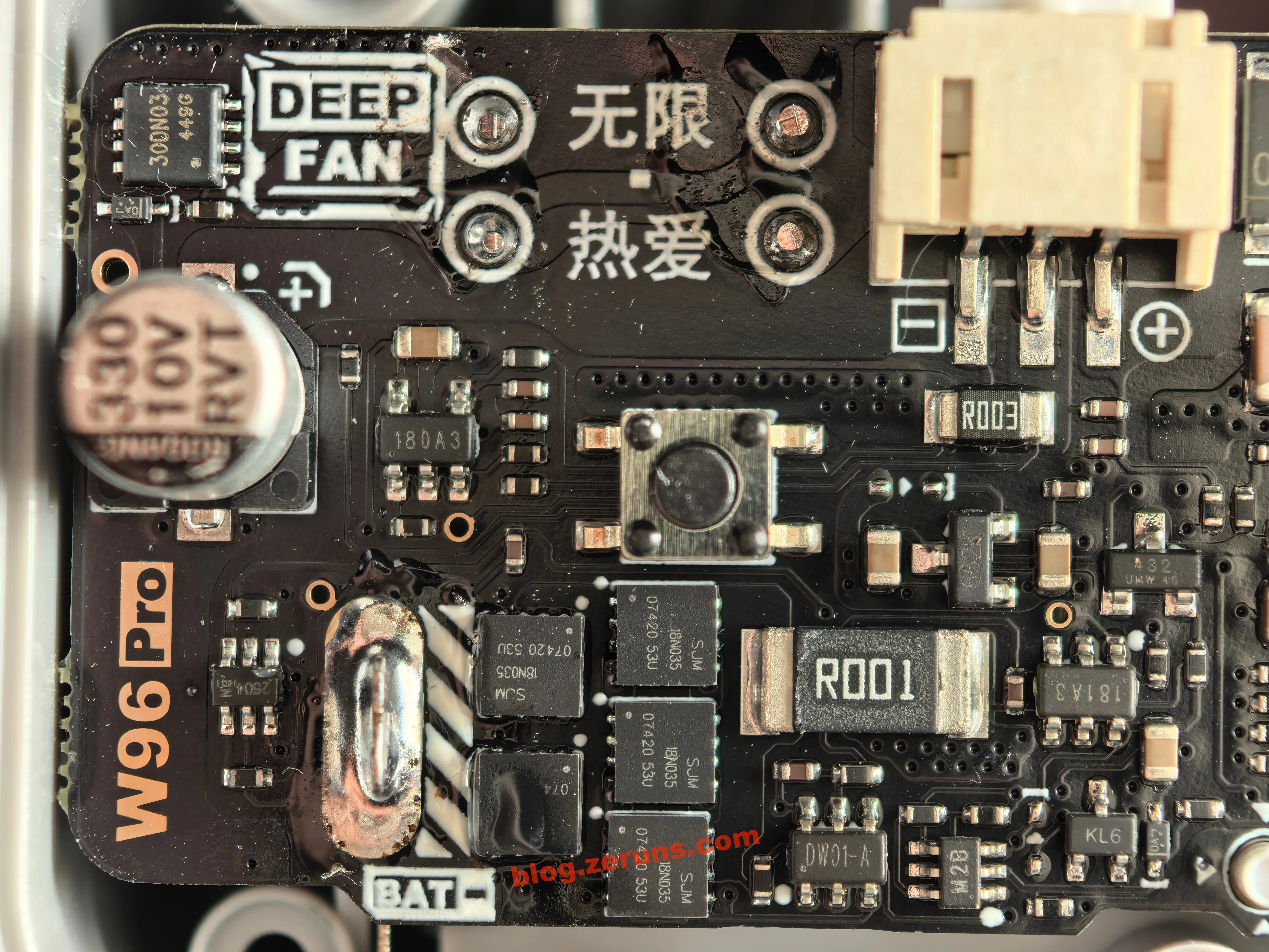
The circuit at the motor interface and battery negative terminal is shown below.
A R003 current-sense resistor, 3mΩ, is connected in series with the motor interface negative terminal. After being amplified by an operational amplifier marked 180A3, it is sent to the ADC of the main-control MCU.
The battery negative terminal passes through the protection circuit and then through a R001 current-sense resistor, 1mΩ. After being amplified by an operational amplifier marked 181A3, it is sent to the ADC of the main-control MCU. The coulomb counter is probably implemented using the current measured through this sense resistor, with the coulomb counting done in software inside the main-control MCU.
INA180A3 is a 26V unidirectional current-sense amplifier from Texas Instruments, in a SOT-23-5 package, with fixed gain of 100V/V.
- Common-mode input range: −0.2V ~ +26V, can sample on the high side or low side and is not limited by the supply
- Bandwidth about 150kHz, offset voltage ≤±150µV, offset drift ≤1µV/℃, gain error ≤±1%
- Supply 2.7~5.5V, quiescent current ≤260µA, operating temperature −40~+125℃
INA181A3 is a 26V bidirectional current-sense amplifier from Texas Instruments, in a SOT-23-6 package, with fixed gain of 100V/V and a REF reference pin for distinguishing charge/discharge direction.
- Common-mode input range: −0.2V ~ +26V; bandwidth about 150kHz, offset voltage ≤±150µV, gain error ≤±1%
- Supply 2.7~5.5V, quiescent current ≤260µA, operating temperature −40~+125℃
- After the REF pin is connected to a reference potential, output above/below the reference corresponds to discharge/charge current, respectively
Note: TI’s official marking for this chip does not appear to be the model number directly, so these two op amps on this board may be domestic replacement chips.
To the upper right of the 181A3 chip, there is also a TL432 voltage-reference chip. It provides a voltage reference for the 181A3, giving the bidirectional battery-current measurement a stable “zero point” at the REF pin potential, so that charge and discharge directions can be distinguished relative to the reference.
TL432 specifications, AI-generated:
- Core function: three-terminal adjustable precision shunt reference, programmable Zener diode, with internal bandgap reference + error amplifier. Output voltage is set by an external two-resistor divider and can be continuously adjusted from 2.5V to 36V
- Accuracy: graded, commonly ±0.5%, B grade, ±1%, A grade, ±2%, standard grade
- Output current: 1mA to 100mA when used as a shunt regulator/reference
- Temperature coefficient: about 30ppm/℃, some manufacturers specify 50ppm/℃; low drift ensures stable reference voltage
- Dynamic impedance: typically about 0.2Ω
- Package: SOT-23-3 / SOT-23-5 / TO-92, etc.; compatible models include KA432, LM431, AS431, and others
- Function: TL432 outputs a stable voltage, for example using two resistors to divide 3.3V into a 1.65V midpoint, and connects it to the REF pin of the INA181A3. This makes the amplifier output sit at the midpoint when there is “zero current” — during charging, the output is above the reference; during discharging, it is below the reference, so the main controller can distinguish the current direction by reading the ADC
In the upper-left corner of the circuit board, there is an NMOS marked 300N03. Its specs are probably 30V 30A, and I assume it is used to control the charging and discharging of the Farad capacitor, preventing the capacitor from being charged directly when the battery is installed, which could otherwise cause a large inrush current and a big spark.
The lithium battery protection circuit is to the right of the battery negative terminal and uses a “DW01A protection IC + multiple high-current MOSFETs” solution.
DW01A specifications (AI-generated):
- Core function: Single-cell lithium-ion/polymer battery protection IC. It monitors the battery voltage and the current at the CS pin, then drives an external dual N-MOS to disconnect the charge/discharge circuit.
- Overcharge protection: 4.3V ±50mV (some manufacturers mark it as 4.28V), release voltage 4.1V, delay about 100ms.
- Over-discharge protection: 2.4V ±75mV, release voltage 3.0V, delay about 50ms.
- Overcurrent protection: CS pin detection threshold 0.15V (the sampling point is generally placed directly on the MOSFET, using the voltage drop generated by the MOSFET’s internal resistance). Charging overcurrent threshold is −0.15V, with a delay of about 7~10ms.
- Short-circuit protection: Threshold about 1.0~1.35V, delay only 300~600µs.
- 0V battery charging: Supported (can be activated after deep discharge).
- Quiescent current: About 3~6µA; low-power mode about 0.7µA.
- Package: SOT-23-6 (also available in SOP-8 and other variants). There are many domestic compatible models (Fuman, Changxin, etc.).
SJM 18N035 specifications (AI-generated):
- Type: N-channel enhancement-mode power MOSFET.
- Voltage rating: VDS ≈ 30V.
- Current rating: ID ≈ 18A.
To the left of the battery negative terminal, there is also a 6-pin chip marked 2604. I couldn’t find any datasheet for it, so I don’t know what it does, but it should also be related to battery protection. The Gongtian F95D mini fan I took apart last time also had this chip.
To the right of the DW01A, there is also a 6-pin chip marked M2B, and I couldn’t find any information on it either, so I don’t know what it does.

Motor control waveforms at different speed levels
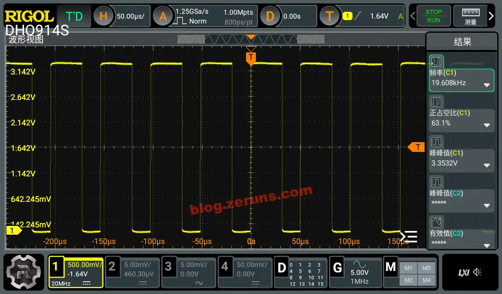
Using a DHO914S oscilloscope, I measured the waveform at the motor PWM control pin. At 25% fan speed, the PWM frequency was 19.6kHz, with a duty cycle of 63.1%.

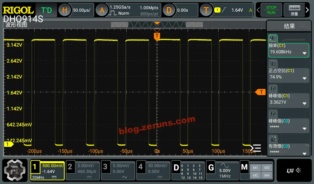
At 50% fan speed, the PWM frequency was 19.6kHz, with a duty cycle of 74.9%.

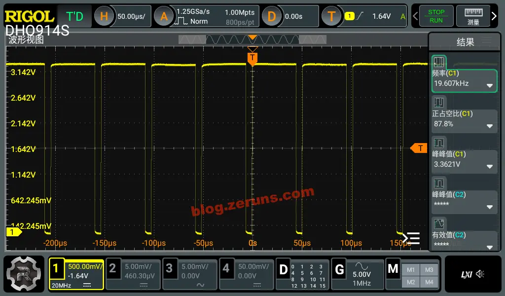
At 75% fan speed, the PWM frequency was 19.6kHz, with a duty cycle of 87.8%.

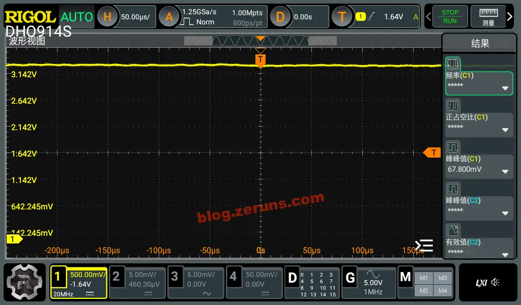
At 100% fan speed, the duty cycle is 100%, meaning it stays continuously on.

Summary
- The circuit uses decent components and has plenty of design margin.
- The companion mini program is fully featured and provides quite a lot of data.
- The 18W charging power is pretty good, and it can also be used as a charger for other devices.
- The wind speed and airflow are good. The highest setting is quite noisy, while the second setting at 35% offers a good balance between wind speed and noise.
- The wind speed at the highest setting is strong enough that the fan may tip over if it can’t stand firmly.
- At the second setting of 35%, the runtime is about 8 hours, which is decent.
Recommended Reading
- Recommended cost-effective and affordable VPS/cloud servers: https://blog.zeruns.com/archives/383.html
- Recommended AI large model API platforms and introductions: https://blog.zeruns.com/archives/947.html
- Minecraft server setup tutorial: https://blog.zeruns.com/tag/mc/
- Complete guide to deploying Hermes Agent, with step-by-step instructions for building your first AI assistant: https://blog.zeruns.com/archives/939.html
- Unboxing, review, and teardown of the Ugreen DXP4800Pro NAS: https://blog.zeruns.com/archives/949.html
- Understand MQTT in one article: how the “post office” of the IoT world works: https://blog.zeruns.com/archives/951.html
English Version of the Article: https://blog.zeruns.top/archives/99.html