ESP8266 是一款由乐鑫 Espressif 公司制作的低成本的 Wi-Fi 芯片,具有完整的 TCP / IP 协议栈和微控制器功能。它专为移动设备、可穿戴电子产品和物联网应用设计,功耗很低且价格非常低廉。
ESP8266有多种开发环境可以选择,本文讲Arduino IDE的开发环境搭建。
本文所用到的开发板及其他模块,以及连接线购买地址在最下面。
我这里使用的 NodeMcu 开发板即搭载了这款芯片。
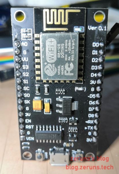
请根据自己的开发板所用的USB转TTL电平芯片下载安装对应的驱动,我的开发板用的是CH340
安装Arduino IDE
Arduino IDE 是由 Arduino 官方提供的支持 C 语言的集成开发环境,主要是针对 Arduino 系列的开发板进行编程。
通过简单的配置,可以在原本的编程环境里添加上对 ESP8266 开发板的支持。对于熟悉 Arduino 函数库和开发流程的用户,基本上没有任何使用上的区别。
Arduino IDE下载地址:
Arduino官网:https://www.arduino.cc/en/Main/Software
腾讯微云:http://go.zeruns.com/E
百度网盘:http://go.zeruns.com/F 提取码: h6cy
添加 ESP8266 支持
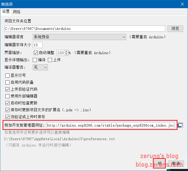
打开Arduino IDE,点击左上角的文件,进入首选项(Preferences),找到附加开发板管理器地址(Additional Board Manager URLs),并在其后输入如下链接: http://arduino.esp8266.com/stable/package_esp8266com_index.json
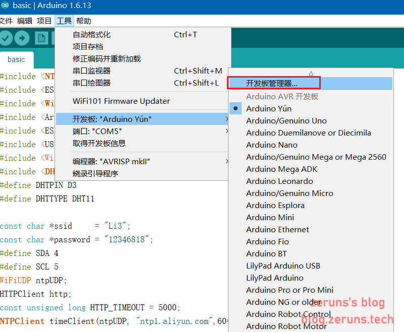
然后点击工具 → 开发板 → 开发板管理器,进入开发板管理器界面:
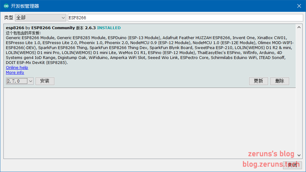
搜索 esp8266 并安装:
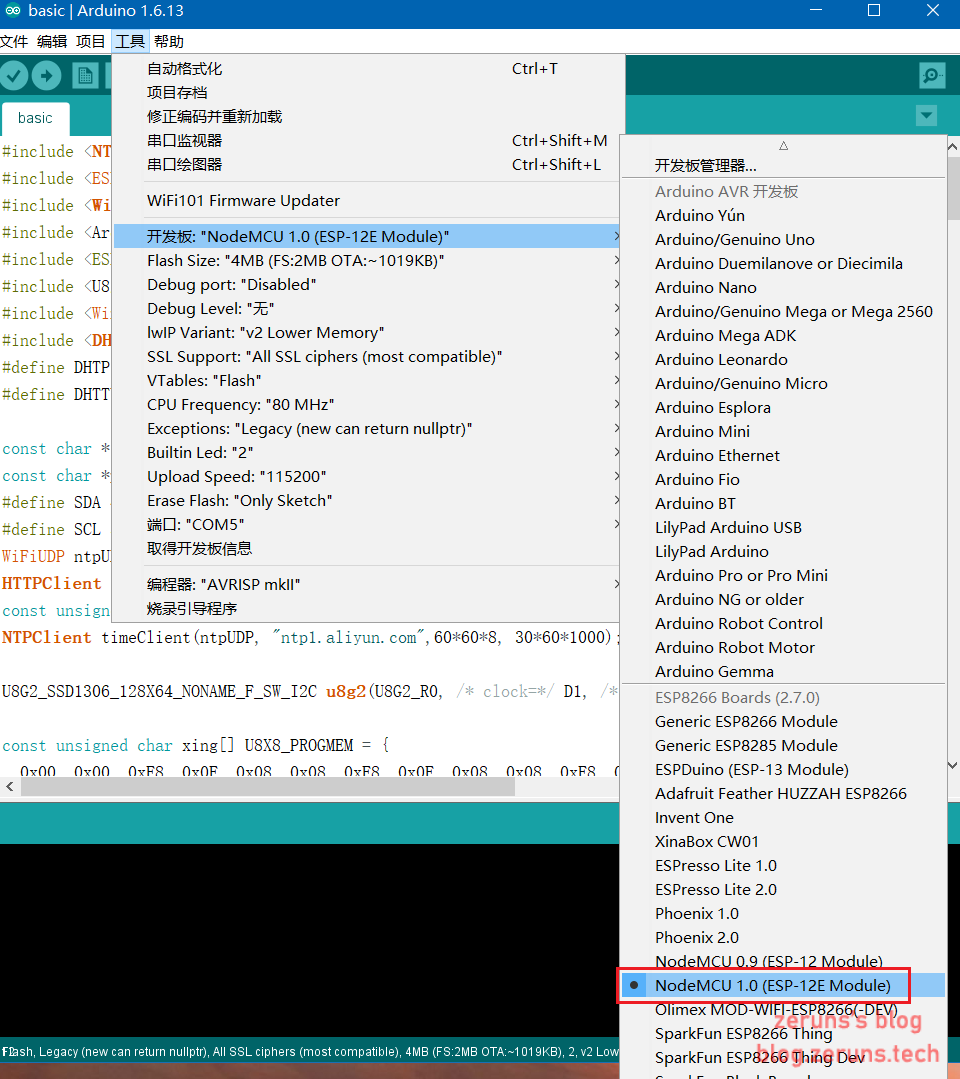
安装完成后,重启 Arduino IDE 软件。在工具 → 开发板选项中即会看到 ESP8266 开发板的选项:
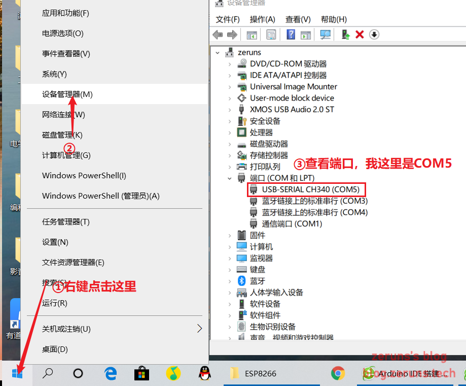
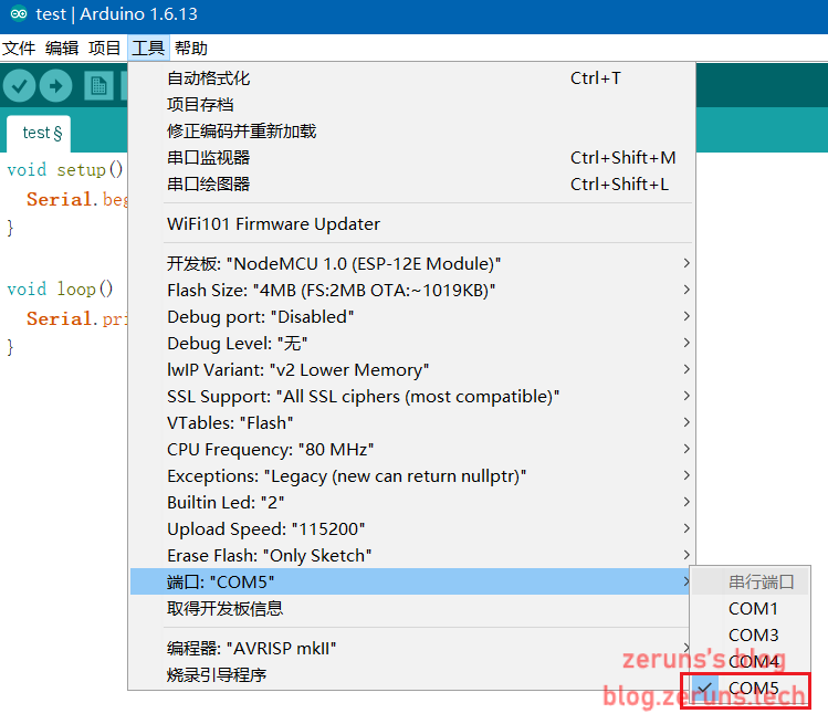
选择端口,先在设备管理器中查看端口,然后在arduino ide中选择对应端口。
项目演示
向串口发送Hello World
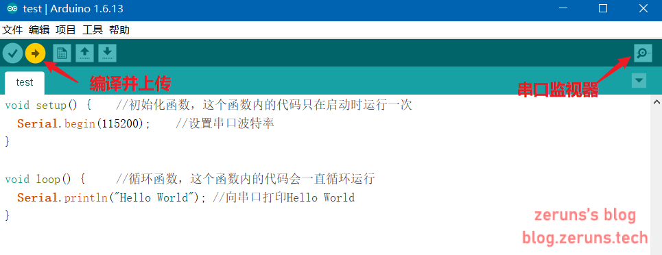
在 Arduino IDE 中新建项目并写入如下代码:
void setup() {    //初始化函数,这个函数内的代码只在启动时运行一次
  Serial.begin(115200);    //设置串口波特率
}
/*
https://blog.zeruns.com
*/
void loop() {     //循环函数,这个函数内的代码会一直循环运行
  Serial.println("Hello World"); //向串口打印Hello World
}
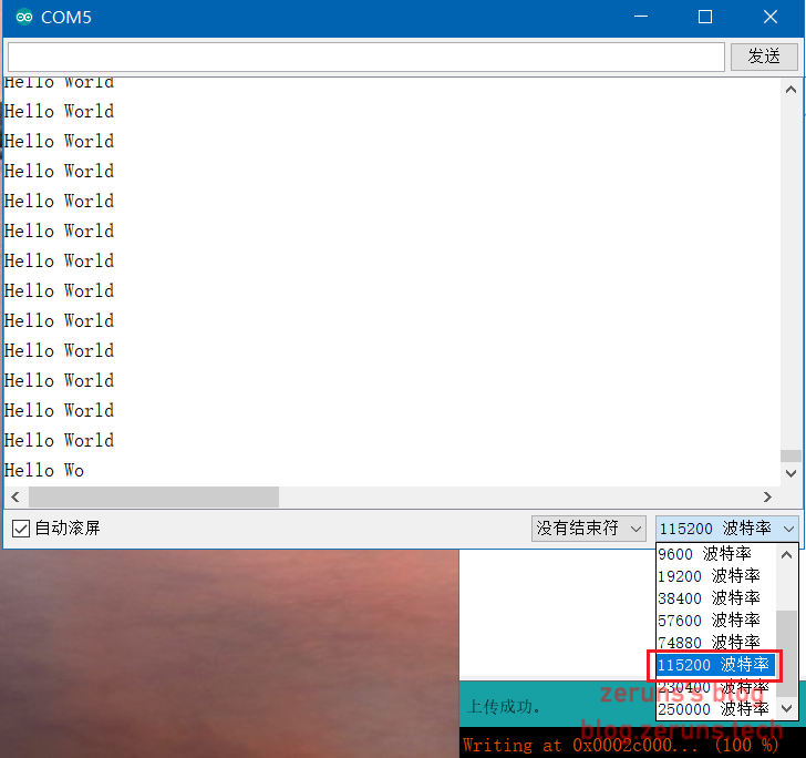
输入后点击 上传键进行编译上传到开发板,然后打开 串口监视器,选择波特率115200即可看到输出的Hello World。
LED闪烁
ESP8266模块上自带一个LED,这个LED接的是D4口。
注意:ESP8266有多种开发板,不同的开发板的GPIO口不一样。
void setup() {          //初始化函数,这个函数内的代码只在启动时运行一次
  pinMode(D4,OUTPUT);  //设置GPIO口D4状态为输出模式
}

void loop() {             //循环函数,这个函数内的代码会一直循环运行
  digitalWrite(D4,HIGH);  //设置GPIO口D4输出高电平,HIGH可以用1代替
  delay(1000);            //延时1000毫秒
  digitalWrite(D4,LOW);   //设置GPIO口D4输出低电平,LOW可以用0代替
  delay(1000);			  //https://blog.zeruns.com
}
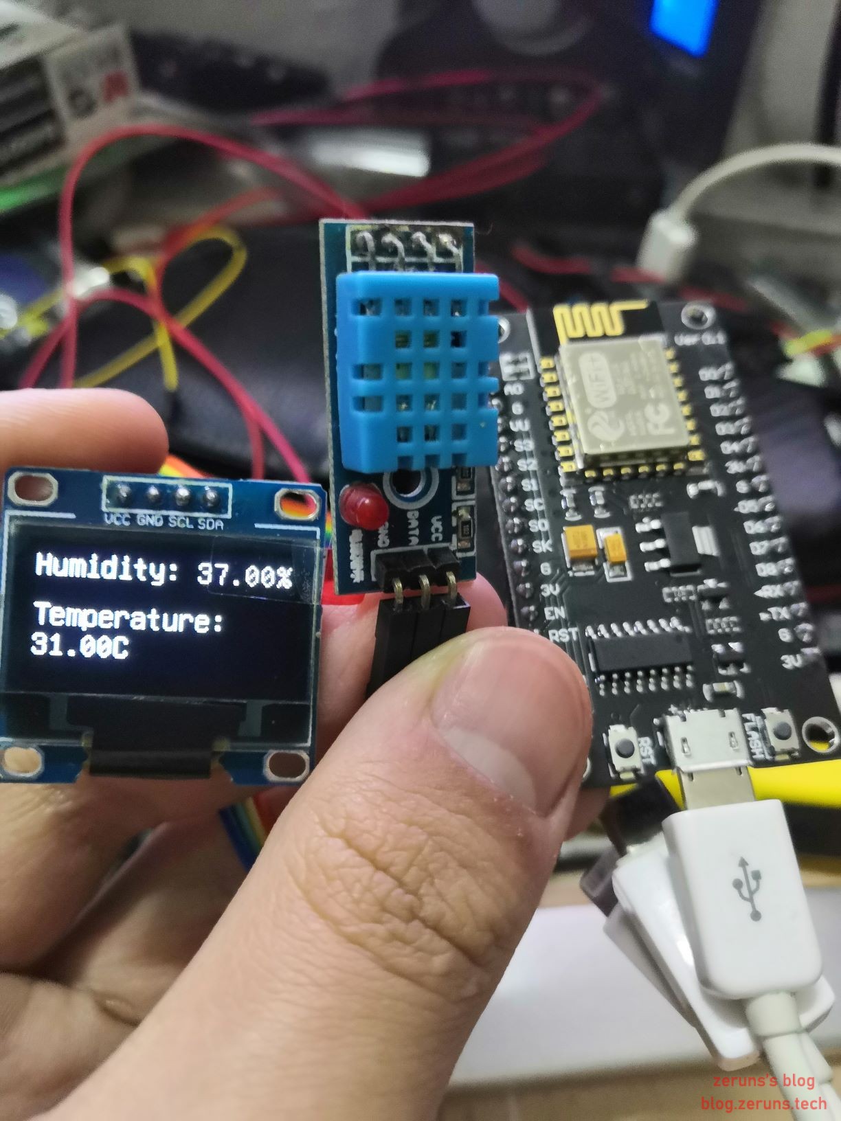
读取DHT11数据并显示出来
本例中使用 DHT11 温湿度传感器 测量温度和湿度,再把测量所得的结果输出至 0.96寸的OLED屏幕 中。
项目源码:
#include <Arduino.h>
#include <NTPClient.h>
#include <U8g2lib.h>
#include <DHT.h>

#ifdef U8X8_HAVE_HW_SPI
#include <SPI.h>
#endif
#ifdef U8X8_HAVE_HW_I2C
#include <Wire.h>
#endif

DHT dht(D3,DHT11, 15);
U8G2_SSD1306_128X64_NONAME_F_SW_I2C u8g2(U8G2_R0, /* clock=*/ D1, /* data=*/ D2, /* reset=*/ U8X8_PIN_NONE);

void setup(){
  u8g2.begin();
  u8g2.enableUTF8Print();
  dht.begin();
}

void loop() {
  float h = dht.readHumidity();
  float t = dht.readTemperature();
  u8g2.clearBuffer();
  u8g2.setFont(u8g2_font_unifont_t_chinese2);
  u8g2.setFontDirection(0);
  u8g2.setCursor(0, 15);
  u8g2.print("Humidity:");
  u8g2.setCursor(80, 15);
  u8g2.print(h);	//https://blog.zeruns.com
  u8g2.setCursor(120, 15);
  u8g2.print("%");
  u8g2.setCursor(0, 40);
  u8g2.print("Temperature:");
  u8g2.setCursor(0, 55);
  u8g2.print(t);
  u8g2.setCursor(40, 55);
  u8g2.print("C");
  u8g2.sendBuffer();
  delay(1000);
}
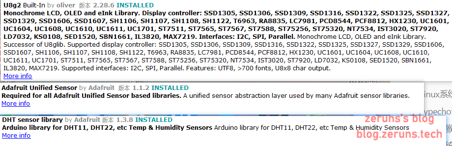
由于源代码中首行引入的 DHT库 和 U8g2库 并不是 Arduino IDE 内置的库文件,需要先点击项目 → 加载库 → 管理库进入库管理器,搜索安装如下三个依赖库(Adafruit Unified Sensor 和 DHT sensor library 和 U8g2):
线路连接
| NodeMcu | DHT11 |
|---|---|
| 3V3 | VCC |
| GND | GND |
| D3 | DATA |
| NodeMcu | 0.96寸OLED |
|---|---|
| 3V3 | VCC |
| GND | GND |
| D1 | SCL |
| D2 | SDA |
WiFi连接
ESP8266 最大的特性就是其超低成本的 Wi-Fi 实现。
这里简单贴出其连接 Wi-Fi 的示例代码:
#include<ESP8266WiFi.h>
const char* ssid = "blog.zeruns.com"; //wifi名
const char* passwd = "blog.zeruns.com"; //wifi密码
void setup() {
Serial.begin(115200); //设置串口波特率
WiFi.begin(ssid,passwd); //连接wifi
while (WiFi.status() != WL_CONNECTED) //判断wifi连接状态
{
delay(500);
Serial.print("."); //串口打印 .
}
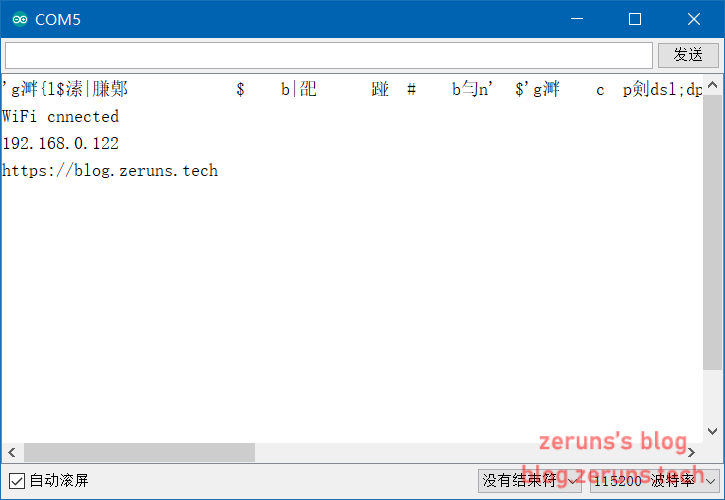
Serial.println(""); //换行
Serial.println("WiFi cnnected");
Serial.println(WiFi.localIP()); //打印获取到的IP地址
Serial.println("https://blog.zeruns.com");
}
void loop() {
}
购买地址
NodeMcu开发板(ESP8266):https://s.click.taobao.com/mWfgiTu
DHT11温湿度传感器模块:https://s.click.taobao.com/gAduxTu
杜邦线:https://s.click.taobao.com/yxUfiTu
0.96寸OLED屏:https://s.click.taobao.com/6IFfiTu
推荐文章
- 高性价比和便宜的VPS/云服务器推荐:https://blog.zeruns.com/archives/383.html
- 搭建内网穿透服务器,带Web面板:https://blog.zeruns.com/archives/397.html
- Arduino读取DHT11,DHT22,SHTC3温湿度数据:https://blog.zeruns.com/archives/527.html
- 怎样搭建个人博客:https://blog.zeruns.com/archives/218.html
- 学生优惠权益大全:https://blog.zeruns.com/archives/321.html