1、EMI 共模电流的产生机理
a.差分电流产生差模电磁场,使得差分回路面积内的走线产生共模电流;
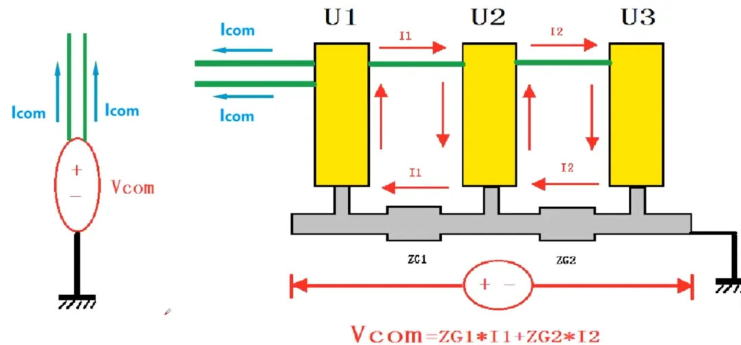
b. (共模电流/辐射主要源头)工作电流经过单板地,由于地阻抗的存在,形成地上共模电压(地电位差),共模电压驱动端口信号,在线束上形成共模电流;
c. 电缆与大地形成的寄生回路,通过磁耦合的方式,感应共模电流;
d.开关电源通过分布参数,如散热器、变压器分布电容,形成共模电流;
e.高速信号/电源平面有高频干扰,相邻层走线会耦合,形成共模干扰。
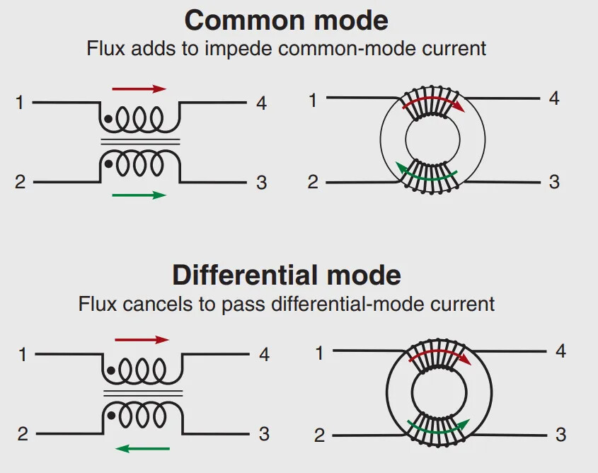
2、共模电感的工作原理
根据右手螺旋定理,当差模电流 流过共模电感线圈时,产生2个相互抵消 的磁场;当共模电流 流过共模线圈时,产生2个相互增强 的磁场,使整个线圈阻抗变高,衰减共模电流。
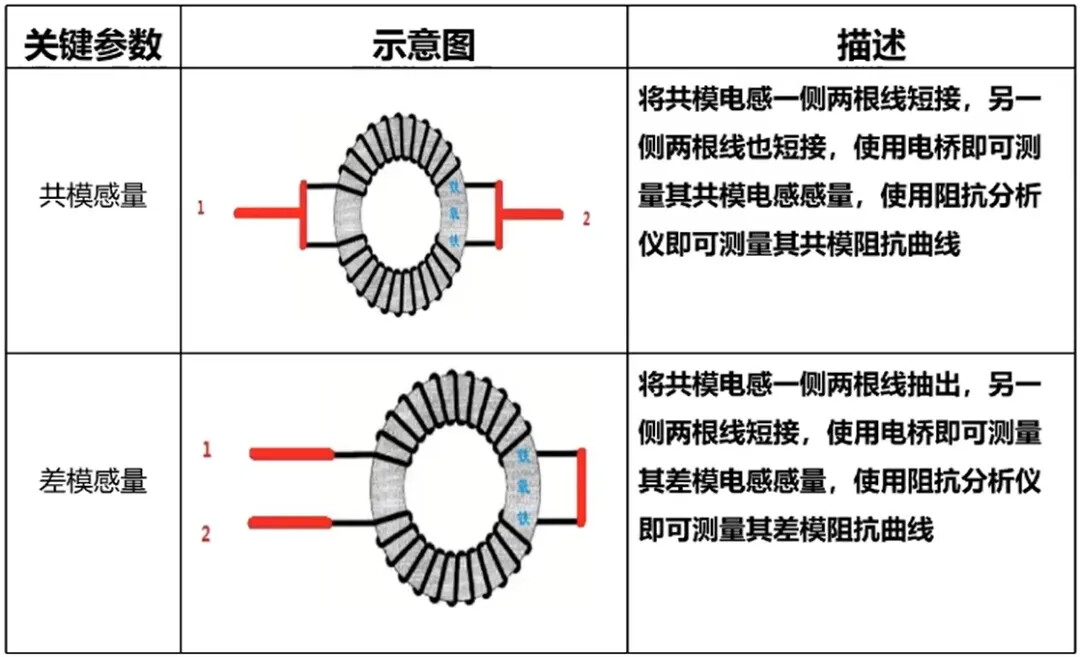
3、共模感量测量
4、共模电感的绕法
a. 双芯并绕(Bifilar)–对称性高,差模阻抗相对较小

b. 2组线圈分别绕(Sectional)–对称性低,差模阻抗相对较大

5、共模电感参数选型
a. AC/DC电源类应用
共模感量 – 电源滤波,大的电感值可以获得更好的滤波效果
差模漏感 – 绕制不平衡产生的感量偏差
额定电流 – 工作电流小于额定电路,需考虑温升和降额设计
额定电压 – 正常工作的额定电压值
直流电阻 – DCR 带来热量损耗,越小越好
耐压值 – 同名绕组线与线之间施加一定的高压,在一段时间内承受的电压值
绝缘电阻 – 绕组与绕组之间的电阻值
b. 差分信号类应用
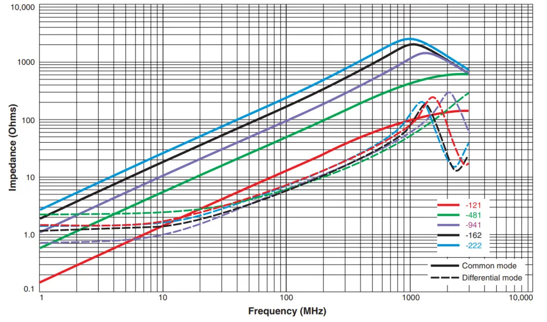
共模阻抗 – 对应相应频率的共模信号,大的阻抗可以获得更好的滤波效果
差模阻抗 – 影响信号传输质量,尽可能接近传输线阻抗;高速数字电路应用时,差模阻抗尽量小,必要时测试眼图/插损
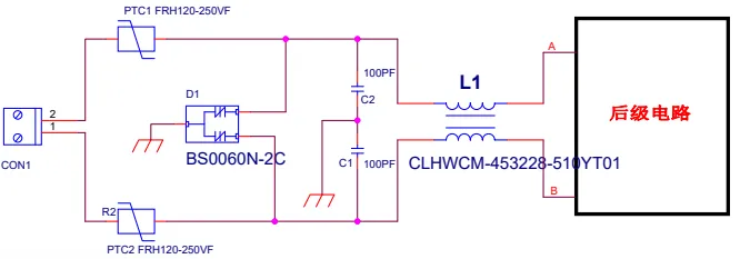
6、共模电感应用
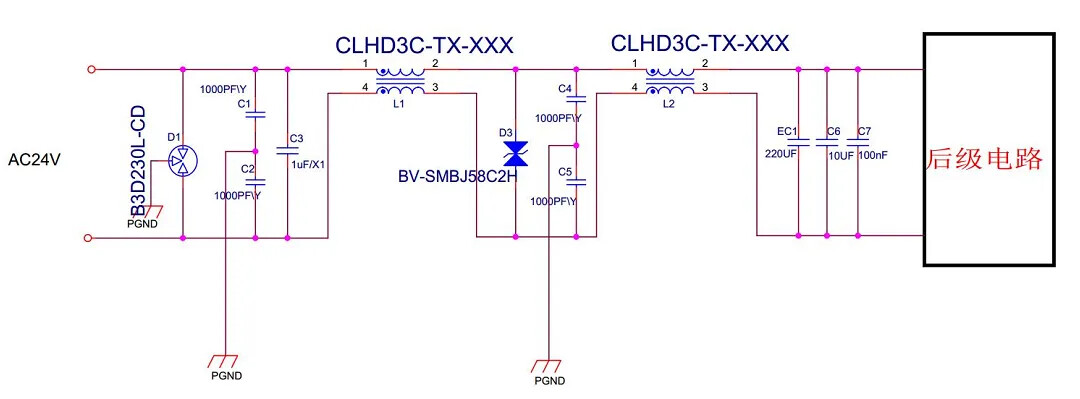
a. AC110-220V输入EMC参考电路
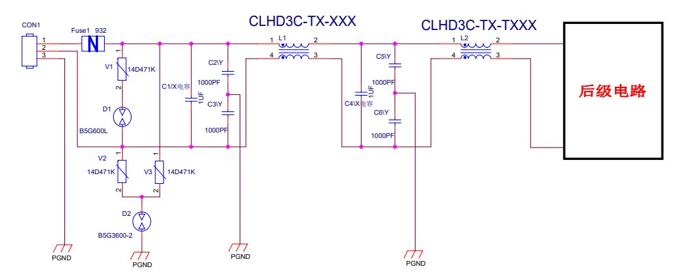
b. AC24V输入EMC参考电路
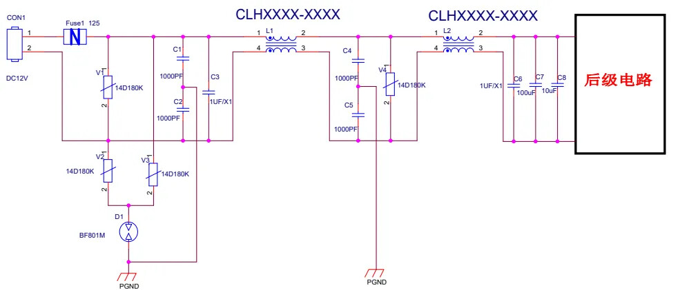
c. DC12V输入EMC参考电路
d. CAN接口EMC参考电路

e. 485接口EMC参考电路