模块现在上电后,芯片VDD引脚串联的led是正常点亮的,但是插上手机或者其他电子设备,不能识别,也不能充电。芯片的sw引脚用示波器量也没有频率
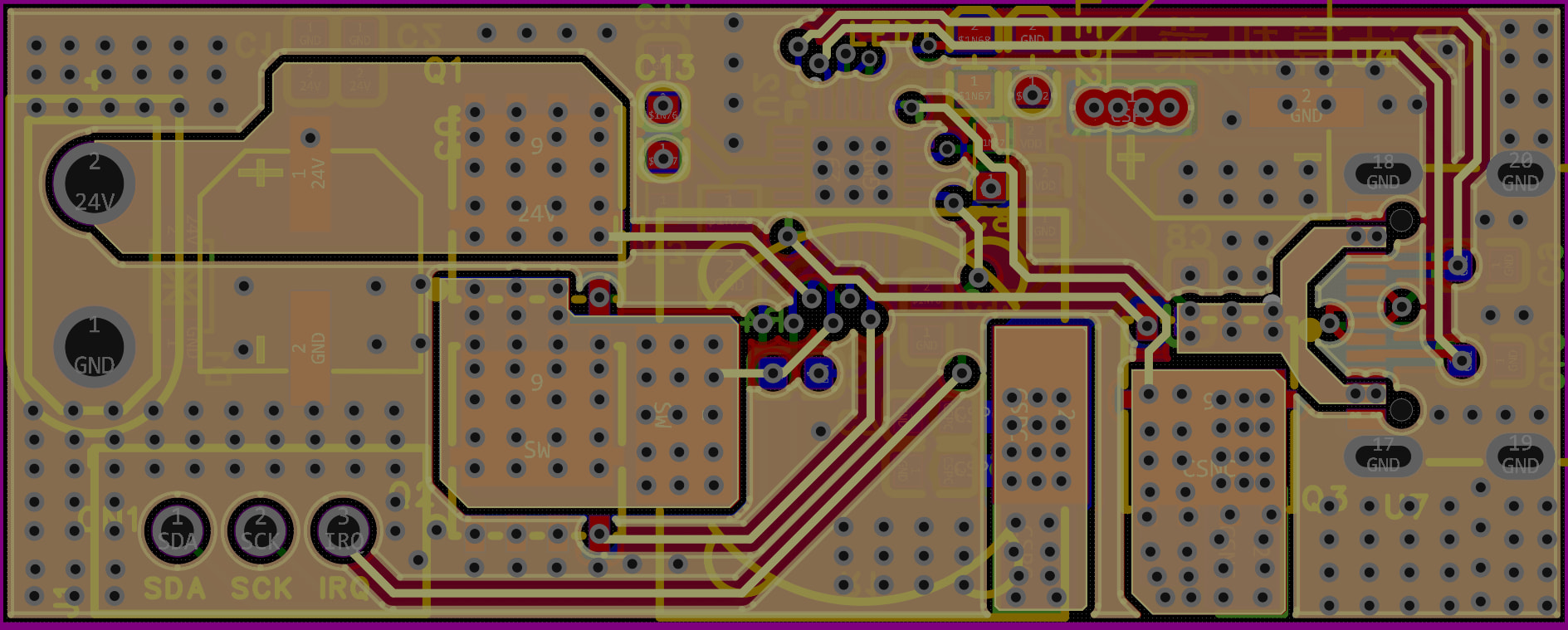
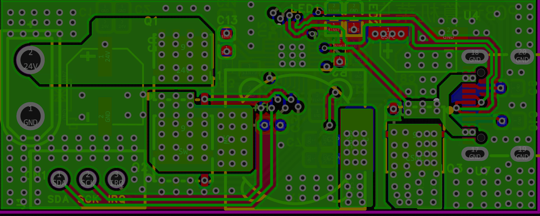
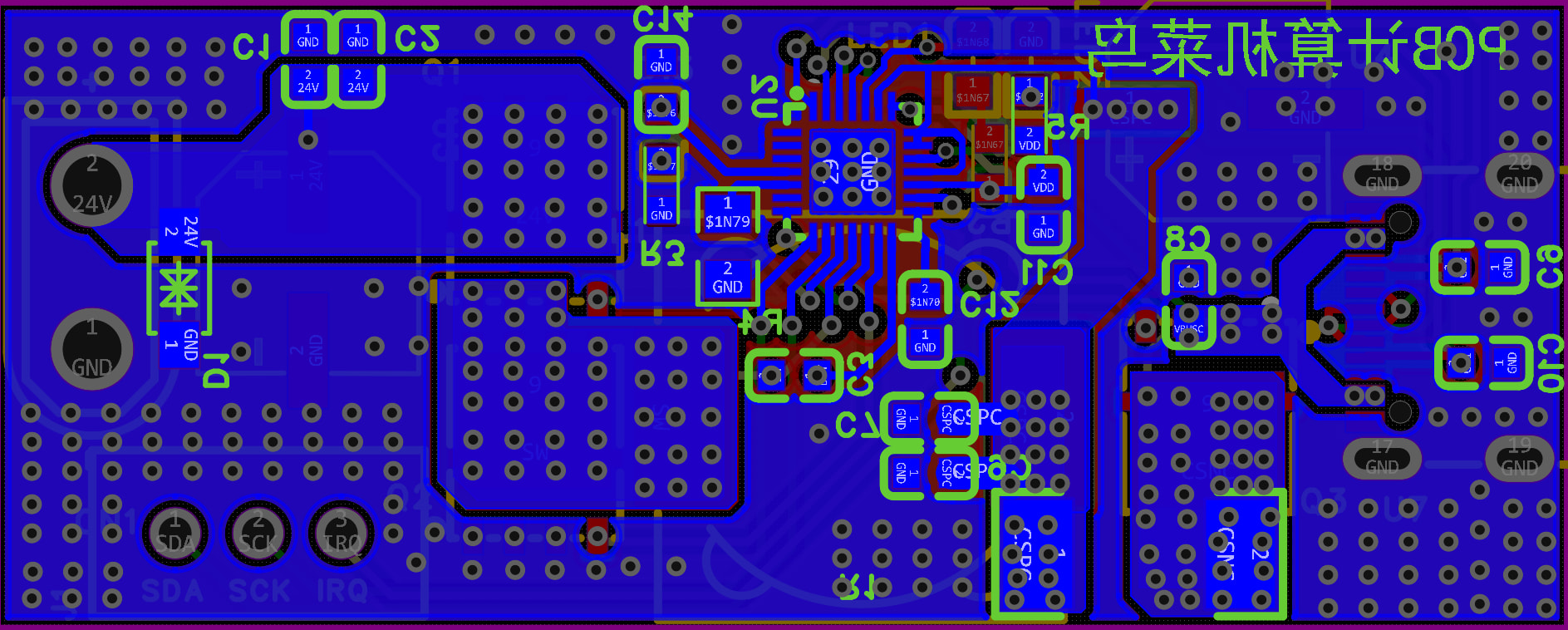
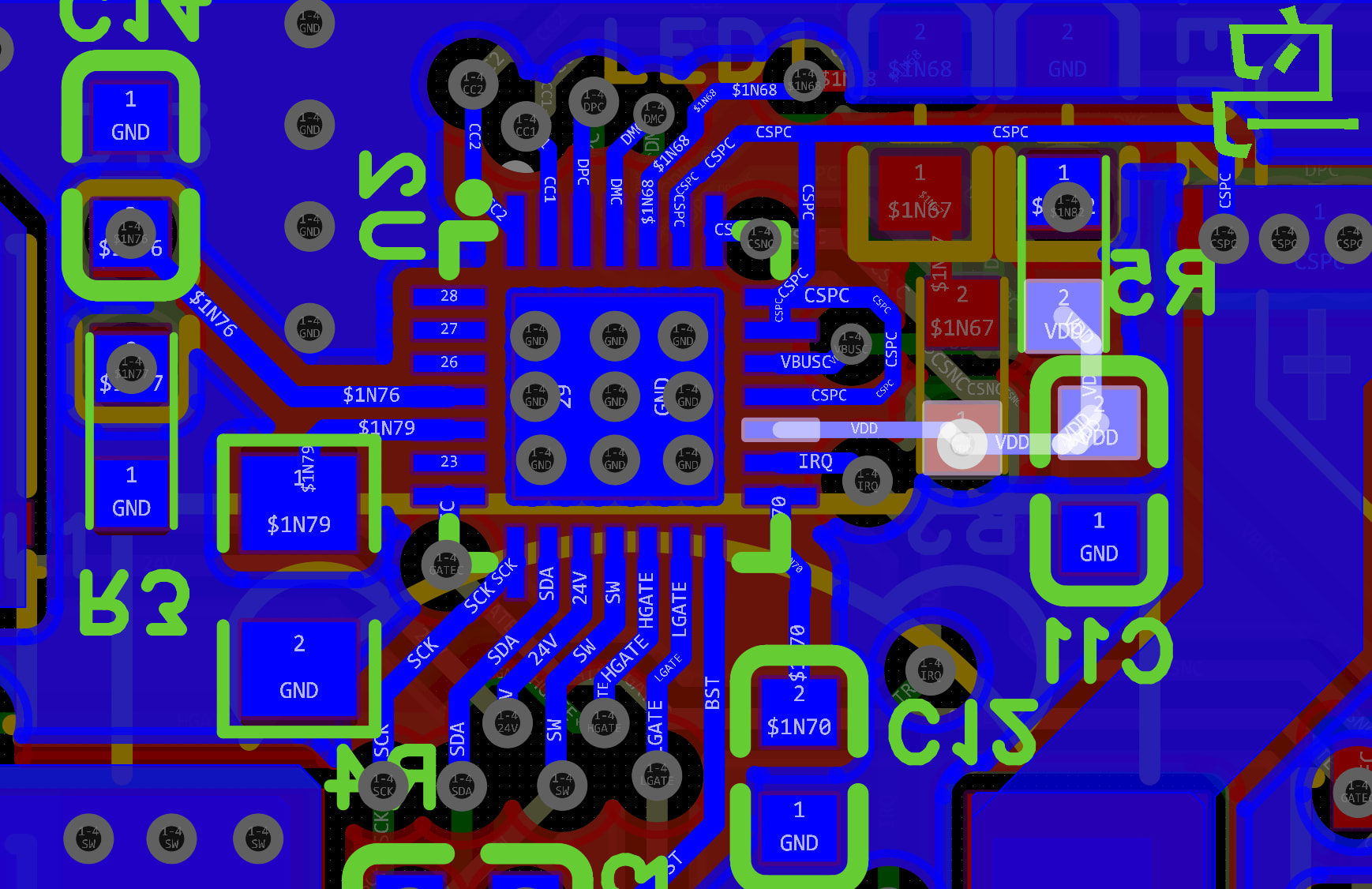
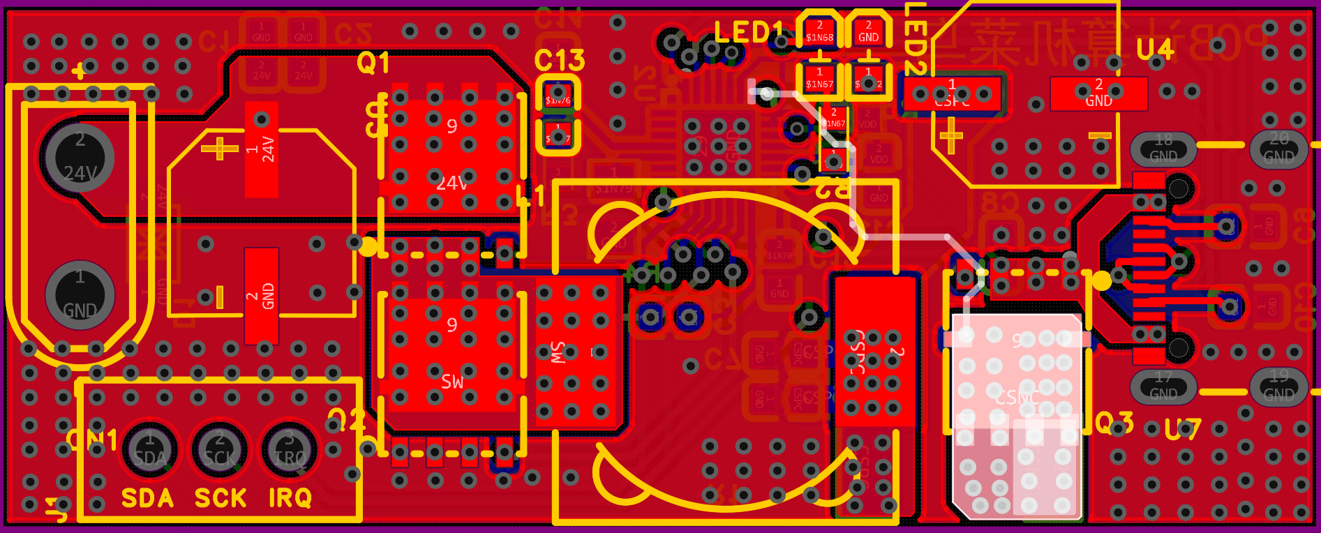
看看你焊接的电路的图片,以及细节图,看看QFN芯片有没有虚焊
建议先做“断肢”检查:
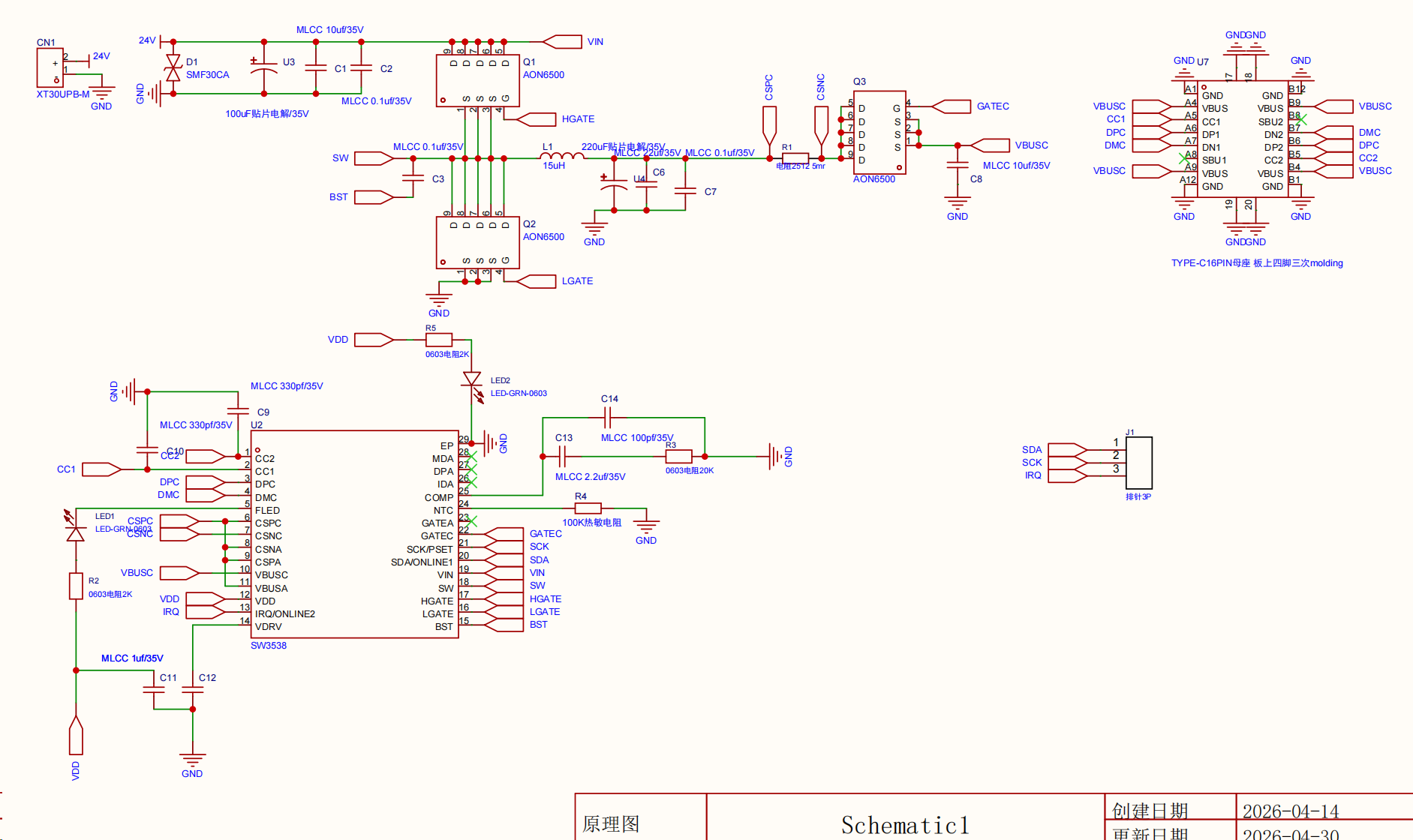
- 断开输出端的 Q3 功率管,看看芯片的 GATEA/GATEB 有没有驱动脉冲。
- 你的 BST 电容(C3) 离芯片有点远,布线太细。自举电容的回路面积必须尽可能小,否则驱动电流不够,上管打不开,SW 也没输出。
- 检查一下 CC 引脚 是否有对地短路。如果你用的是那种带外壳地连通的 Type-C 座子,很容易在焊接时把信号引脚短接到外壳。
为什么你电路上 CSPC、CSPA、CSNA、VBUSA短接在一起了
检查NTC热敏电阻阻值对不对,用错热敏电阻,阻值不对有可能触发过热保护
我看到你的电源路径上有很多过孔,但地线回路呢?从输出电容返回到输入电容的环路需要尽可能短。有一点需要特别注意:检查一下你的NTC电阻 (R4)。如果24脚上的电压不完全符合芯片预期,它就会一直处于热关断状态。既然你的VDD指示灯亮着,说明LDO没问题,所以这肯定是一个逻辑电平的“Inhibit”信号。把NTC拆焊下来,换用一个定值电阻,以排除温度保护方面的问题。
我之前是参考的这个开源方案做的板子,我看他的接线是这么接的https://oshwhub.com/wffg/sw3538_1
我参考数据手册上使用的热敏电阻用的10K的NTC电阻。
我看你链接里这个用的10k的NTC电阻,你直接变成100k了???
我使用的是10K的NTC电阻,我看数据手册上给的接线样例也是10KNTC电阻
你原理图上标注的是100K,还有热敏电阻有多种类型的,正温度系数、负温度系数,还有不同的B值。
如果你不确定自己用的什么热敏电阻,那你可以换个普通10k电阻上去替代试试
抱歉抱歉大佬,我回复的时候少打了个0,我去重新看了看数据手册还有我淘宝购买记录,我用的是100K电阻
好的大佬,我重新试试板子
奇怪,我看数据手册上使用的热敏电阻型号是 104AT,下面是问AI关于104AT的参数
104AT 并不是普通的固定电阻,而是一种非常常见的 NTC(负温度系数)热敏电阻。它由日本石塚电子(Semitec/Ishizuka)首创,因其高精度和高稳定性,目前已成为行业内的通用标准型号。
以下是关于 104AT 的详细参数和具体信息:
1. 命名含义解析
104:代表其在 25^\circ\text{C} 时的标称阻值。前两位数字是有效数字,第三位是 10 的幂次方。
10 \times 10^4 = 100,000 \Omega = \mathbf{100k\Omega}。
AT:代表产品的系列号(AT 系列),主要特征是高精度和小型化。
2. 核心技术参数
参数项 典型值 说明 标称阻值 (R_{25}) 100\text{k}\Omega \pm 1\% 在环境温度为 25^\circ\text{C} 时测得的阻值。 B 值 (B_{25/85}) 4039\text{K} \pm 1\% 反映材料对温度敏感程度的常数(由 25^\circ\text{C} 和 85^\circ\text{C} 确定)。 工作温度范围 -50^\circ\text{C} 至 +110^\circ\text{C} 超过此范围可能导致精度下降或物理损坏。 耗散系数 \approx 2.0\text{mW/}^\circ\text{C} 电阻自身发热导致温度升高 1^\circ\text{C} 所需的功率。 时间常数 \approx 10 - 15 秒 在静止空气中,电阻改变至最终温度差的 63.2\% 所需的时间。 最大额定功率 10\text{mW} 为避免自热效应干扰测量,通常建议实际功率远低于此值。
3. 主要特性
- 负温度系数:随着温度升高,阻值会迅速下降。这一特性使其非常适合作为温度传感器。
- 高精度:104AT-2 系列通常提供 \pm 1\% 的阻值公差,这意味着它在温控电路中不需要复杂的校准。
- 互换性强:由于 4039K 的 B 值已成为行业标杆,许多厂家生产的 100k NTC 都会兼容此参数。
4. 常见应用场景
由于其 100\text{k}\Omega 的阻值在常温下电流损耗极小,它常用于:
- 智能家居:空调、冰箱、热水器的温度监控。
- 电池保护:笔记本电脑、手机电池组的过热监测(BMS)。
- 办公设备:打印机定影器的温度控制。
- 电子温度计:高精度的环境温度测量。
5. 使用建议
在设计电路时,通常使用分压电路将阻值变化转换为电压变化,并输入到微控制器(MCU)的 ADC 引脚。
提示: 如果你在计算温度,请务必使用 Steinhart-Hart 方程 或查阅该型号对应的 R-T 表(电阻-温度对应表)。由于 NTC 的特性是非线性的,简单的线性比例会导致巨大的测量误差。
你是在做具体的电路设计,还是需要该电阻在特定温度下的阻值对照表?
发你热敏电阻购买链接给我看看
你换个10k和100k普通电阻上去试试
【淘宝】https://e.tb.cn/h.R0k031eCoKkrkXf?tk=AcqP5qZE9FM CZ057 「NTC贴片热敏电阻 0805 2.2K 4.7K 6.8K 10K 22K 33K 47K 50K 100K」
点击链接直接打开 或者 淘宝搜索直接打开
大佬!牛逼!我换成100K电阻后能用了模块!!!!谢谢大佬指点!!!!!
我的NTC电阻选的有问题