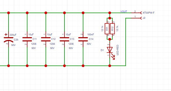
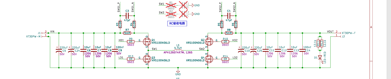
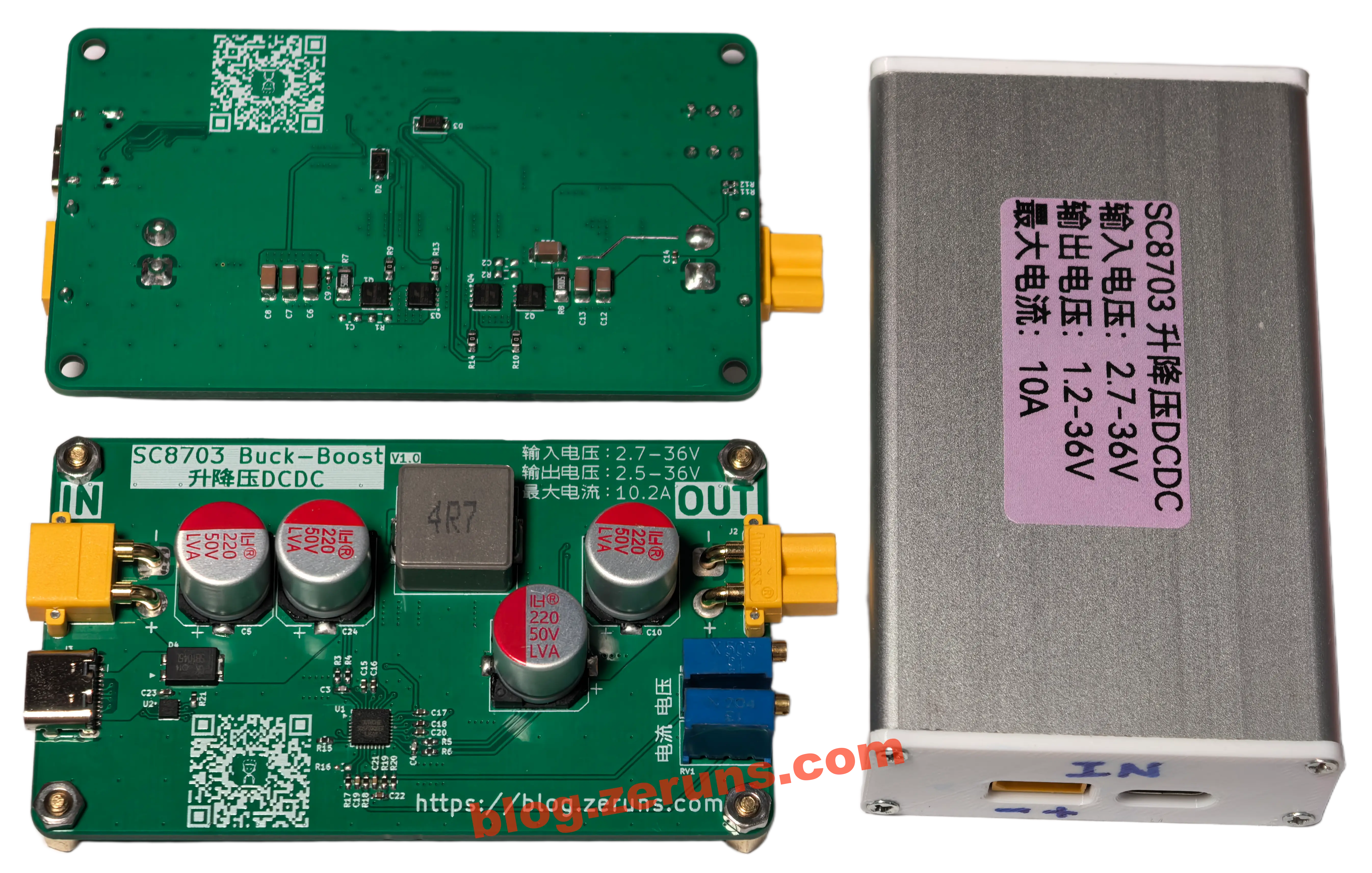
开源一个基于SC8703芯片的Buck-Boost升降压DC/DC电源模块,输入电压最高36V,输入输出电流最高10A,开关频率600kHz,输出电压可调,输出电流恒流可调,最高转换效率95%,输入输出接口XT30,带TypeC口,支持PD快充输入,最高诱骗28V。
设计参数
| 参数项 | 值 |
|---|---|
| 输入电压范围 | 2.7V ~ 36V |
| 输出电压范围 | 1.21V ~ 36V |
| 最大输入/输出电流 | 10A |
| 输出恒流可调范围 | 0.58A ~ 10A |
| 开关频率 | 600kHz |
| PCB尺寸 | 79.6 x 47 mm |
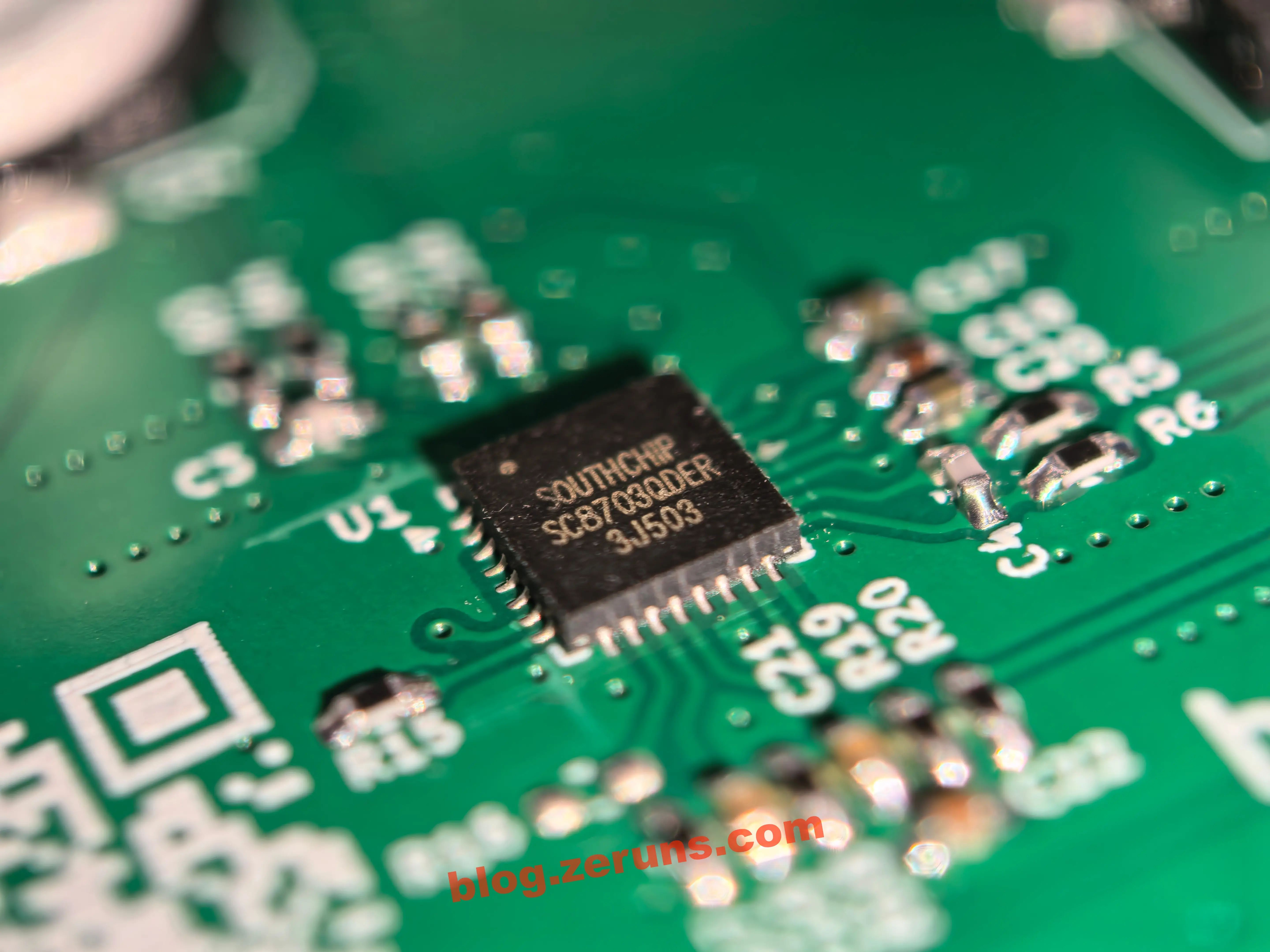
Buck-Boost电源控制器芯片是SC8703,快充协议芯片是CH224Q。
复刻说明
- 本项目使用KICAD设计的,立创开源平台上的立创EDA项目为从KICAD工程文件导入的,所以会有点问题,复刻的建议直接用我提供的Gerber文件下单PCB。
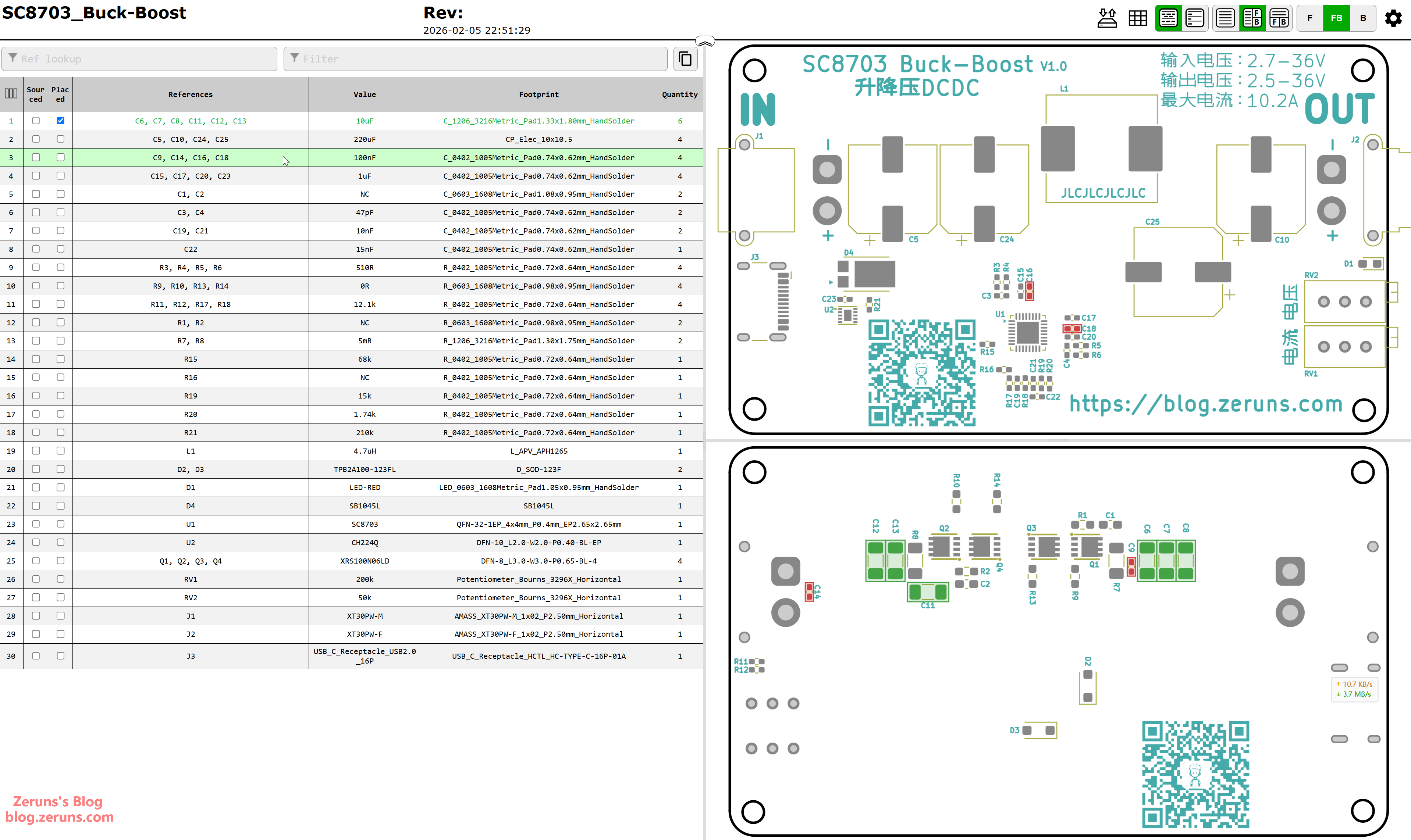
- 项目开源在 Gitee、立创开源硬件平台、华秋开源硬件社区,项目资料和开源平台链接在文章底部,提供的资料有 KICAD项目文件、Gerber制板文件、详细BOM表(表里有元器件购买地址和价格)、顶层和底层拼一起的钢网文件、贴片丝印图、交互式BOM表(焊接辅助)、用到的芯片的数据手册文件、PCBA和外壳3D模型 等。
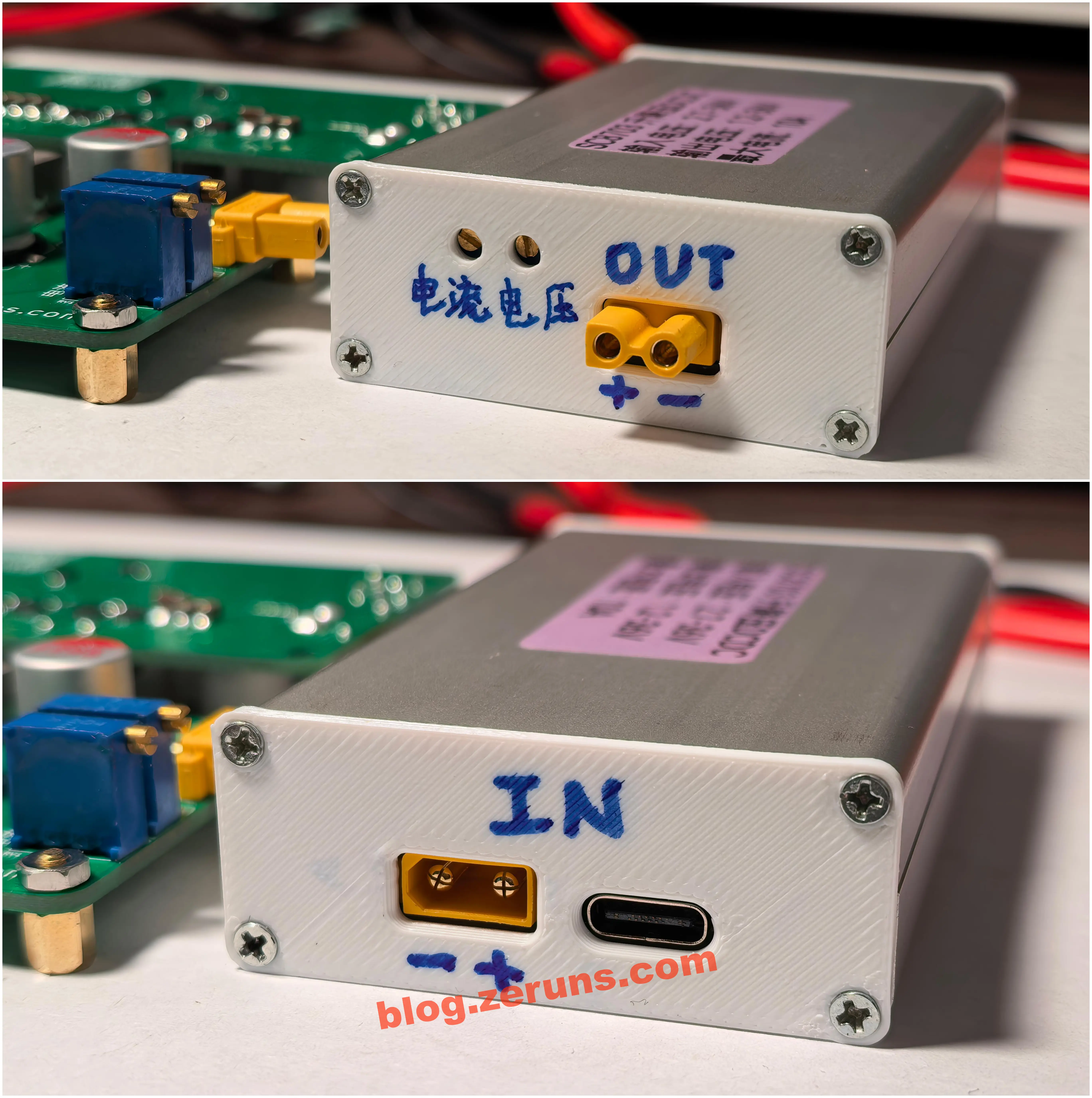
- 外壳是某宝购买的成品铝合金外壳,购买链接已放BOM表,外壳的前后面板是自己3D打印的,3D打印的3mf模型文件在资料里。
- MOS管需通过散热硅胶垫与外壳接触导热!
- 裸板不加散热时建议工作电流在5A以内!
- Type-C口输入XT30输入接口是并联的,禁止同时使用!
小批量的元器件成本大概是30元/套(不含PCB、外壳),主要还是SC8703芯片贵,要9元左右每颗。
![]() 本项目视频演示: https://www.bilibili.com/video/BV1mMfPBzEXH/
本项目视频演示: https://www.bilibili.com/video/BV1mMfPBzEXH/
![]() 电子/单片机技术交流QQ群: 2169025065
电子/单片机技术交流QQ群: 2169025065
![]() eeClub-电子工程师社区: https://bbs.eeclub.top/
eeClub-电子工程师社区: https://bbs.eeclub.top/
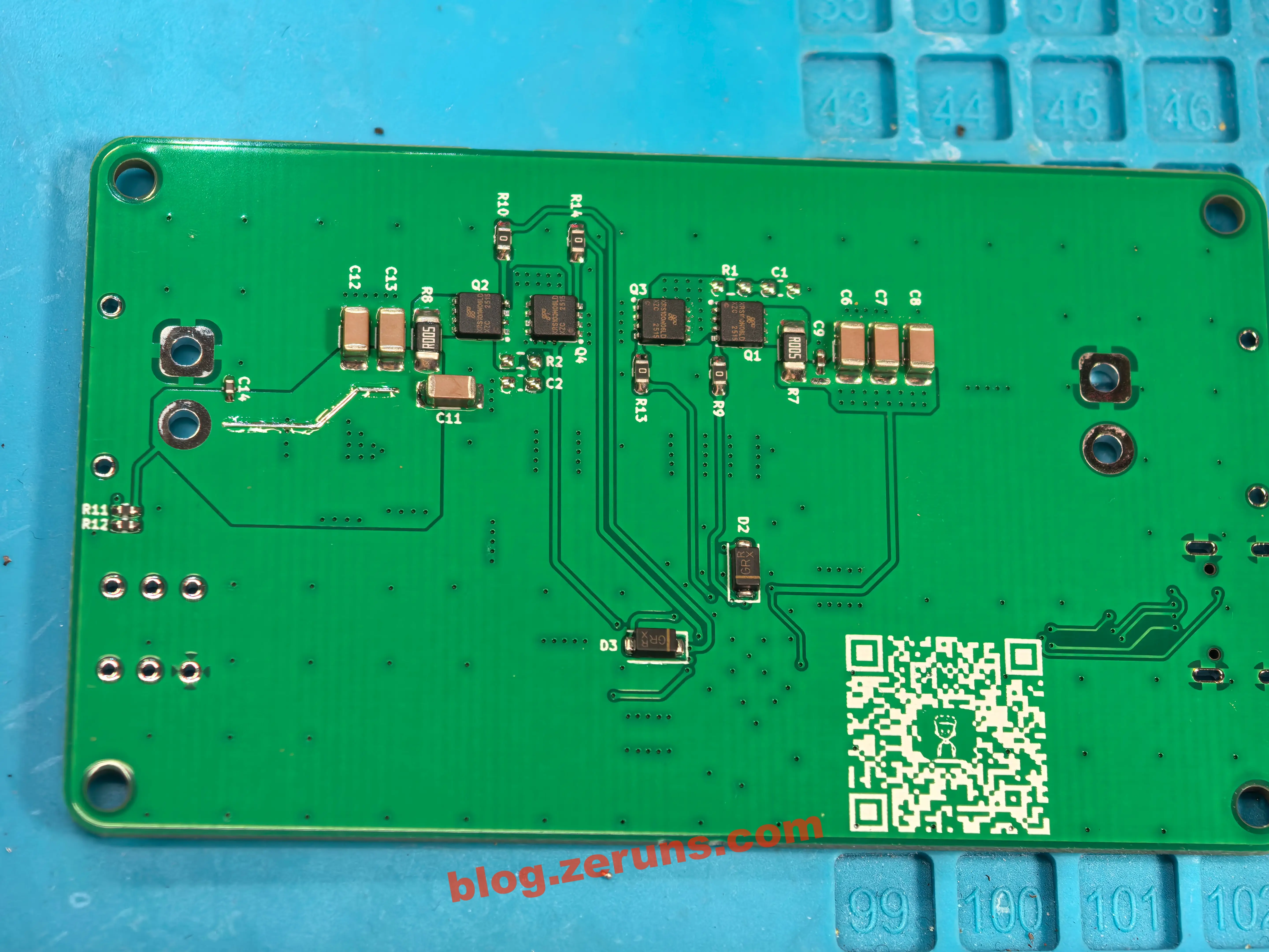
实物图片
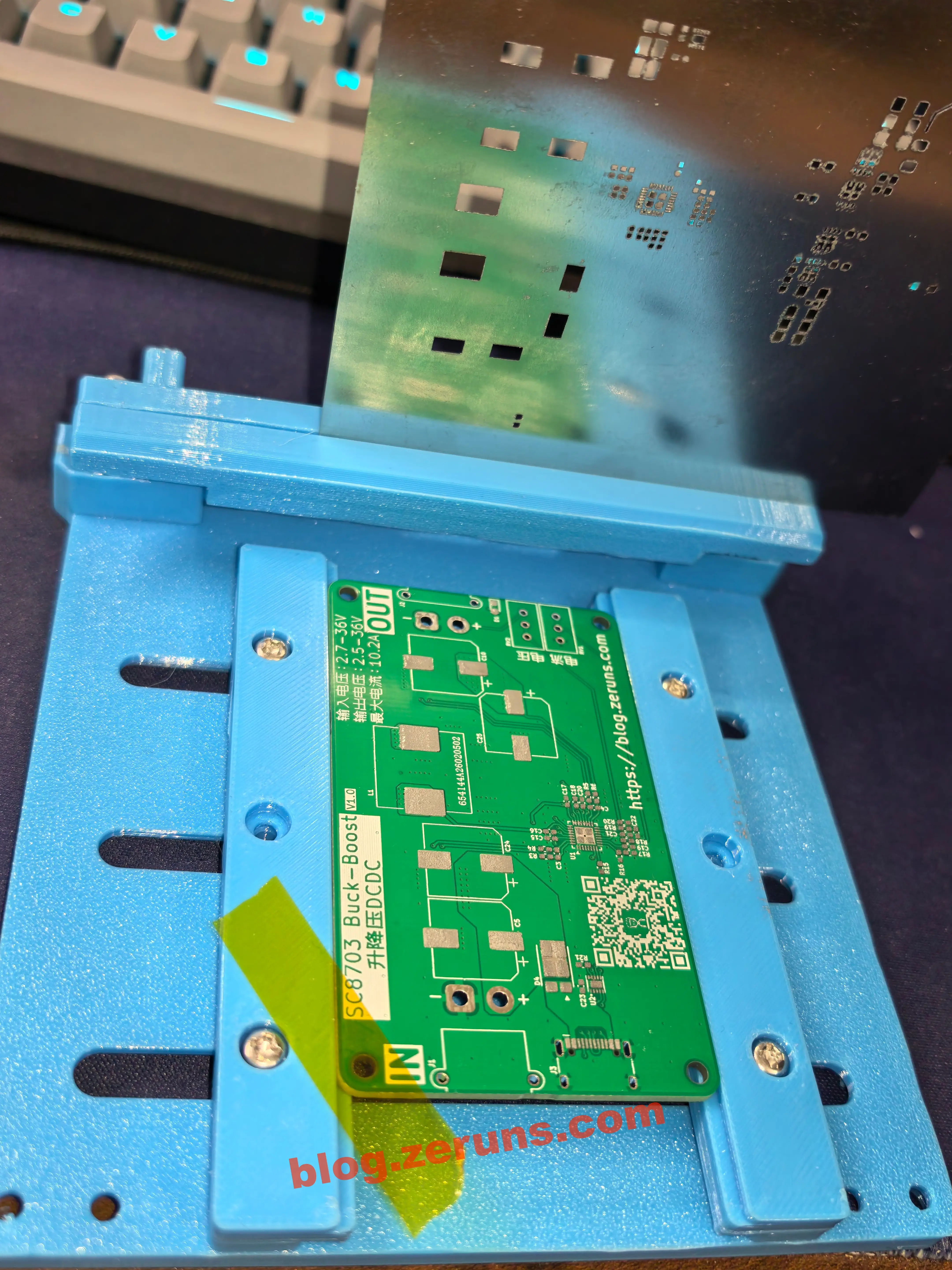
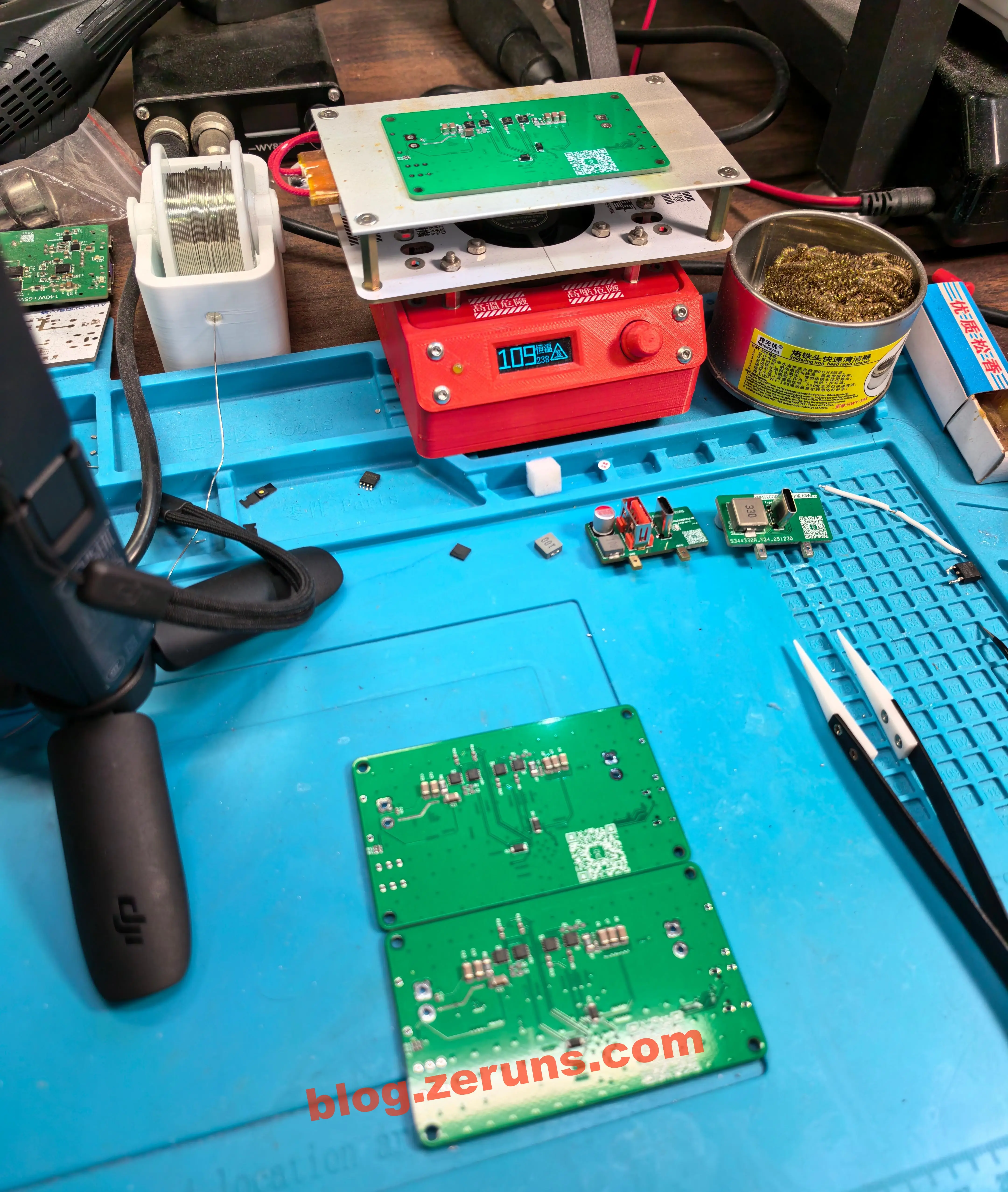
焊接过程
用我提供的钢网文件去某宝打个10x10的钢网大概15元,然后自己3D打印一个刷锡膏的夹具,把钢网和PCB固定并对好位置,刷上锡膏,接着对照着交互式BOM表放好元器件,接着放上加热台或回流焊炉即可,建议先贴底层再贴顶层。
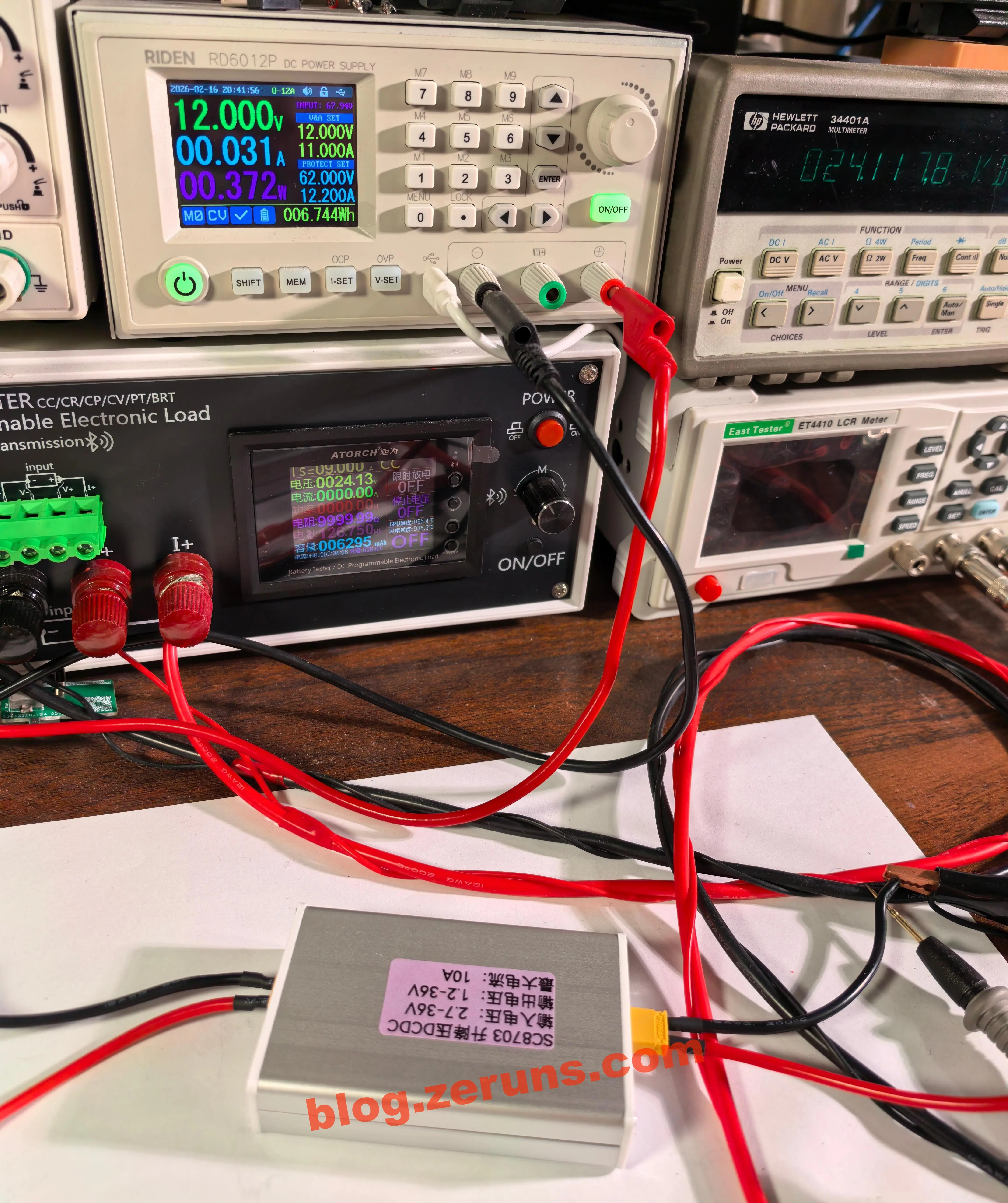
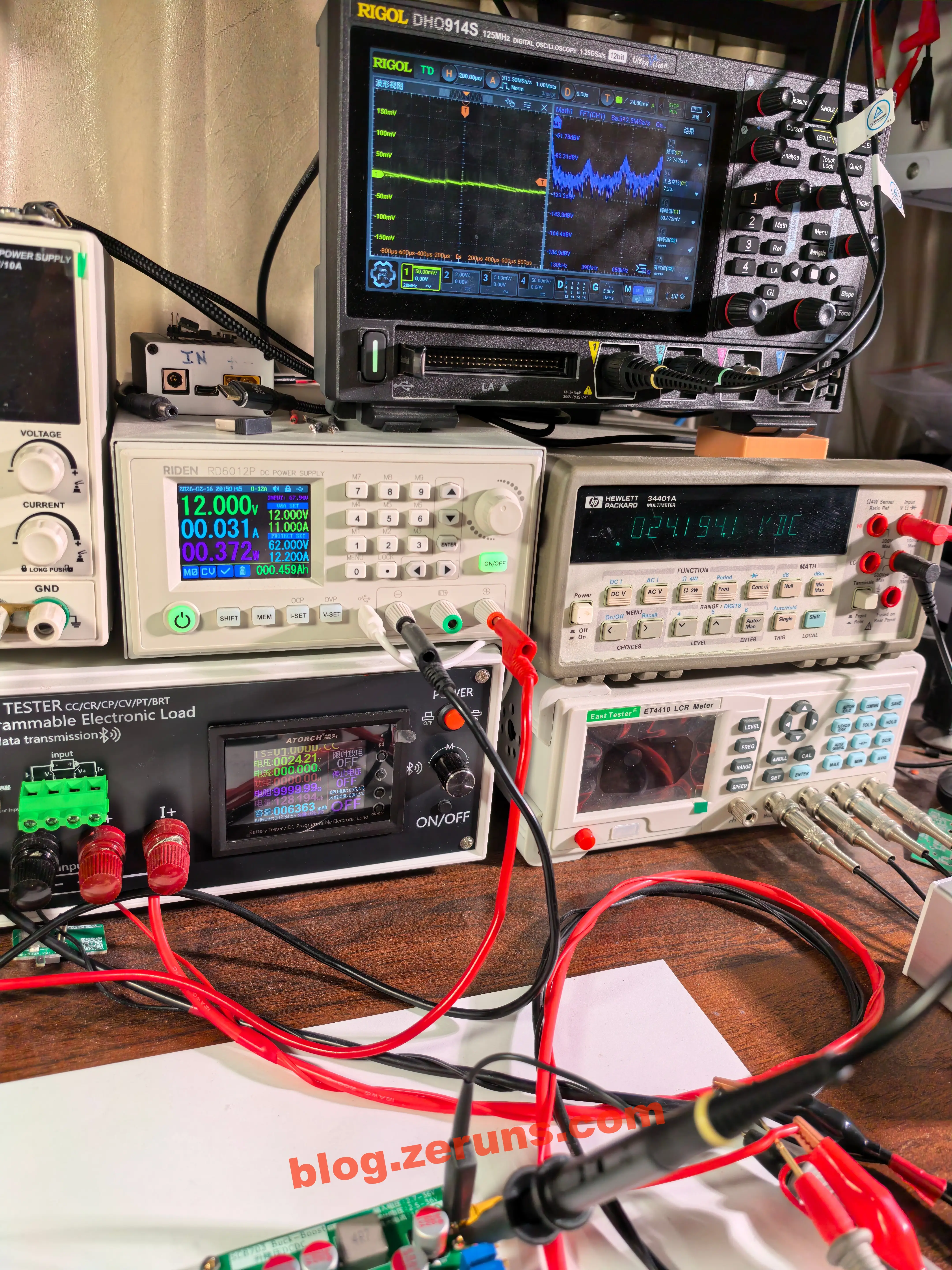
测试
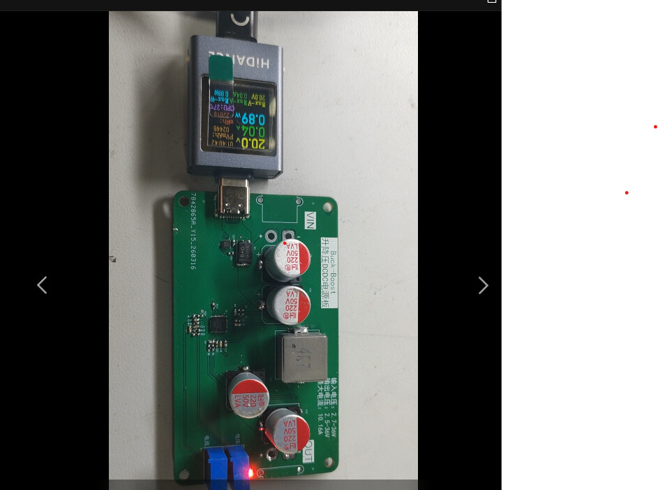
通电测试,输入12V,输出24V,空载功耗0.37瓦左右。
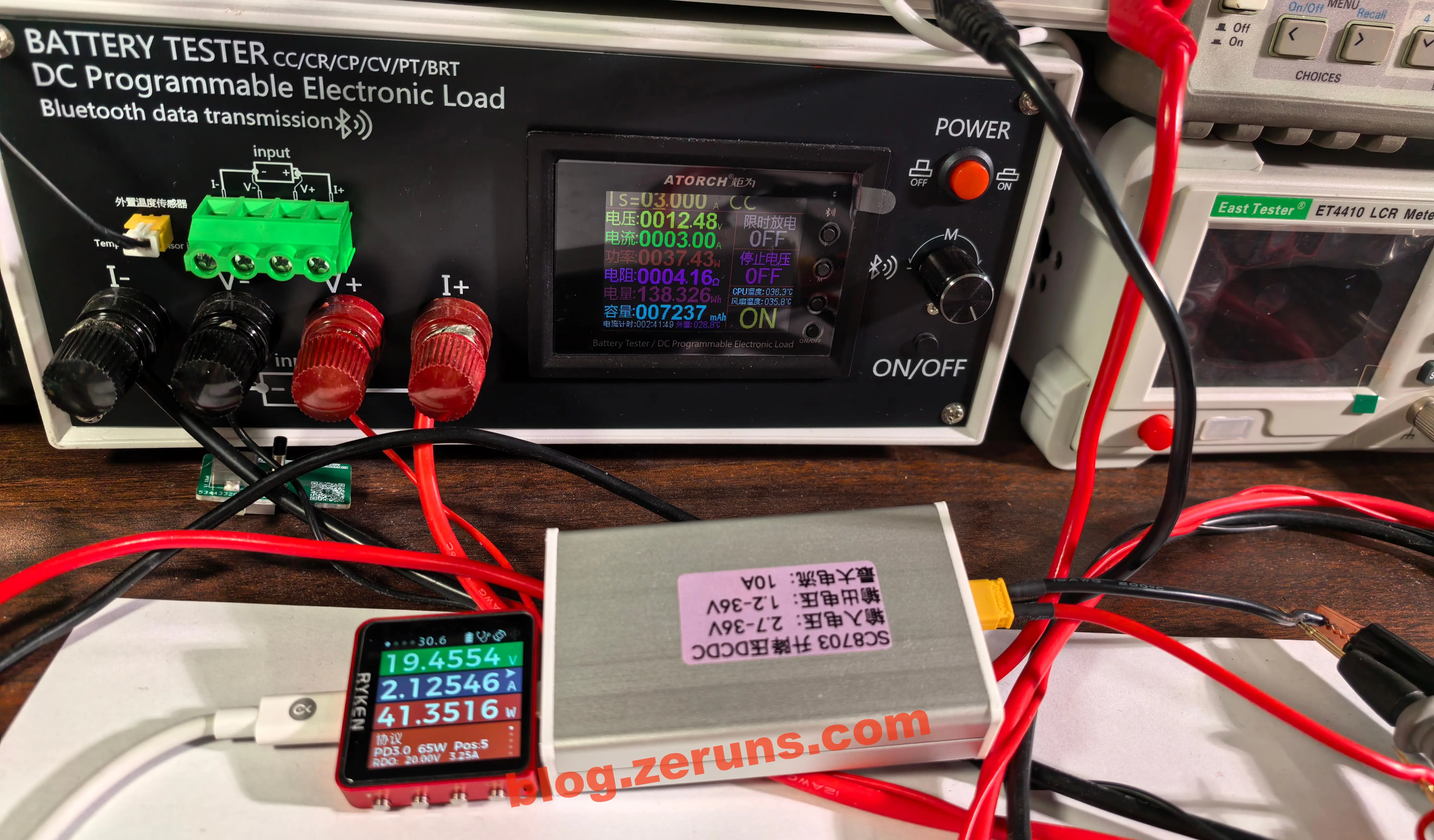
TypeC输入测试,使用65W的PD充电头,诱骗出20V。
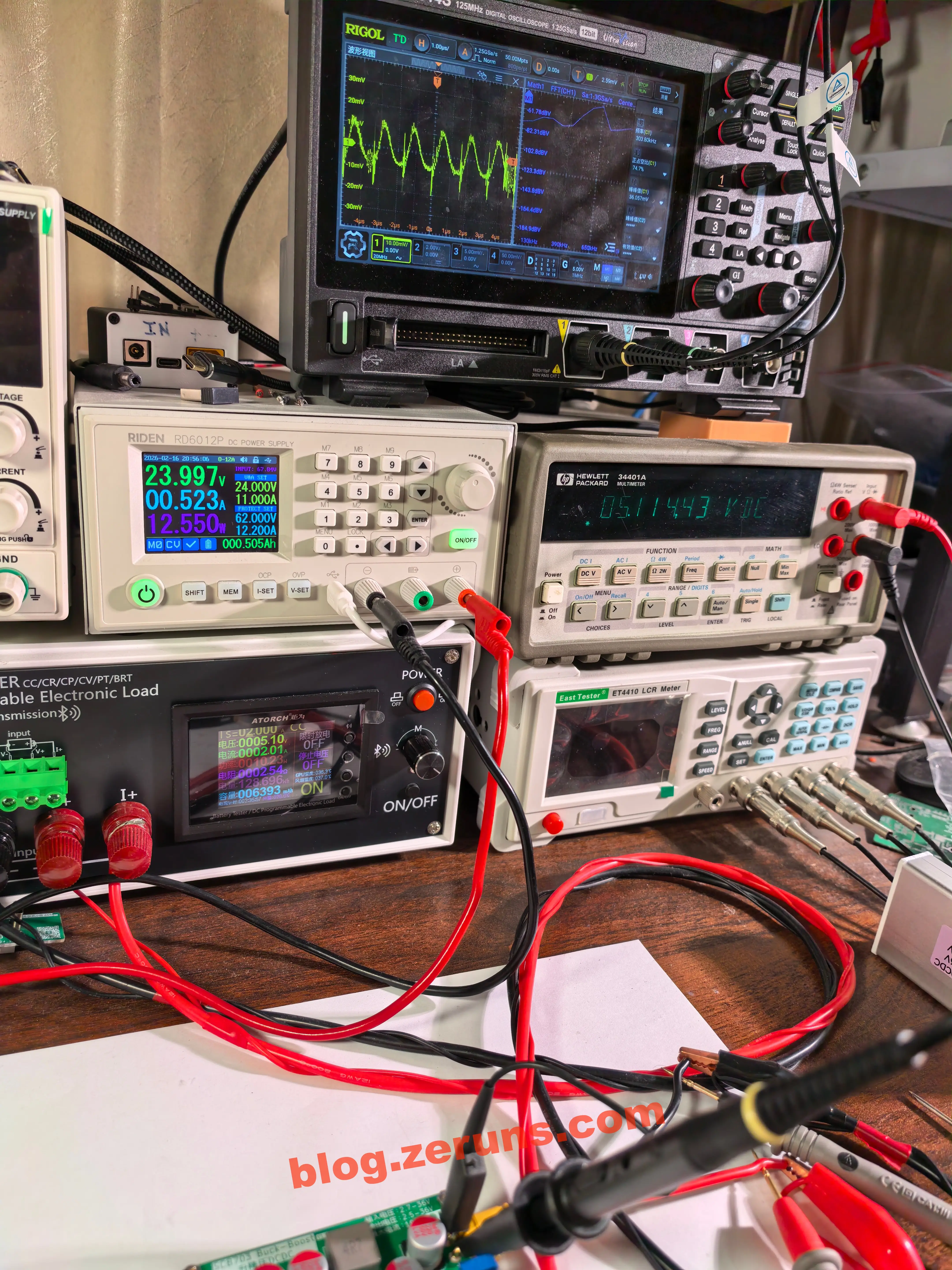
转换效率测试
睿登RD6012P数控可调电源简单开箱评测:https://blog.zeruns.com/archives/740.html
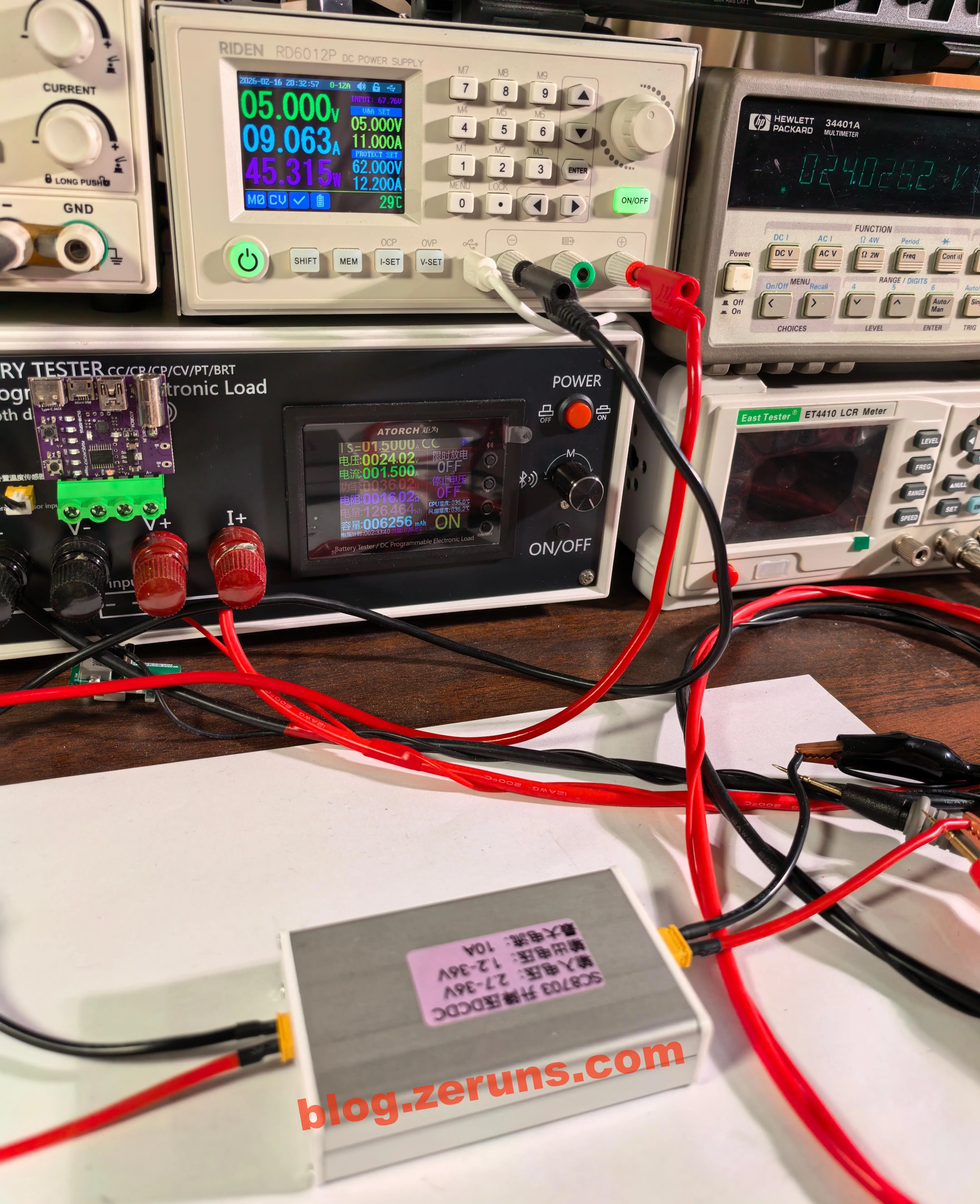
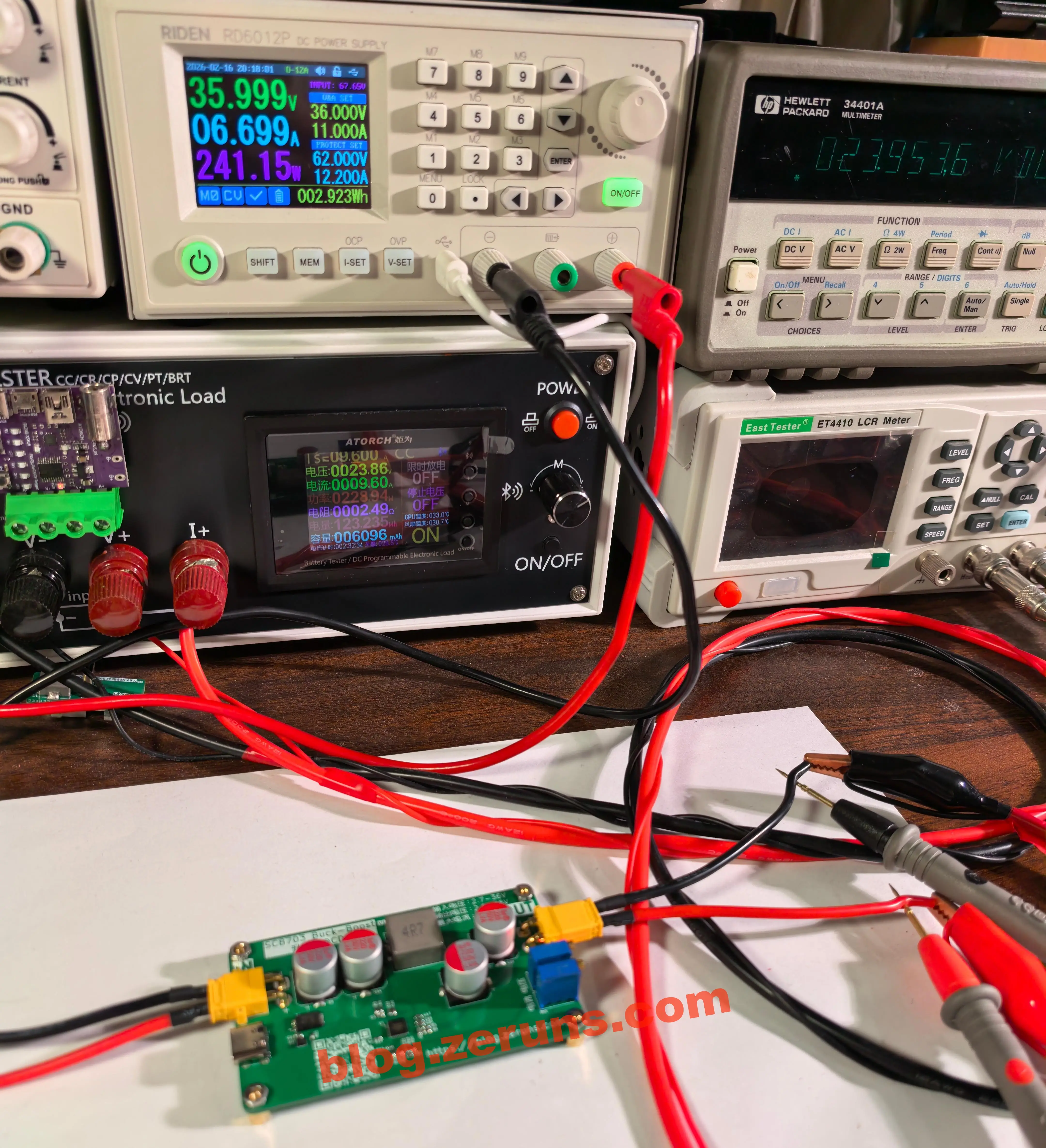
测得最高转换效率95.45%
| 输入电压(V) | 输入电流(A) | 输入功率(W) | 输出电压(V) | 输出电流(A) | 输出功率(W) | 转换效率(%) |
|---|---|---|---|---|---|---|
| 35.999 | 0.752 | 27.071 | 24.130 | 1.000 | 24.130 | 89.14% |
| 35.999 | 6.699 | 241.157 | 23.954 | 9.600 | 229.955 | 95.35% |
| 5.000 | 9.063 | 45.315 | 24.028 | 1.500 | 36.042 | 79.54% |
| 5.000 | 8.520 | 42.600 | 12.054 | 3.000 | 36.162 | 84.89% |
| 12.000 | 4.382 | 52.584 | 5.230 | 9.000 | 47.070 | 89.51% |
| 11.999 | 8.753 | 105.027 | 24.048 | 4.000 | 96.192 | 91.59% |
| 5.000 | 9.803 | 49.015 | 19.990 | 2.000 | 39.980 | 81.57% |
| 5.000 | 5.063 | 25.315 | 21.116 | 1.000 | 21.116 | 83.41% |
| 11.999 | 6.705 | 80.453 | 35.477 | 2.000 | 70.954 | 88.19% |
| 35.999 | 3.459 | 124.521 | 11.998 | 9.510 | 114.097 | 91.63% |
| 35.999 | 1.839 | 66.202 | 12.023 | 5.000 | 60.116 | 90.81% |
| 35.999 | 9.288 | 334.359 | 35.460 | 9.000 | 319.141 | 95.45% |
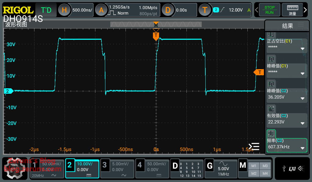
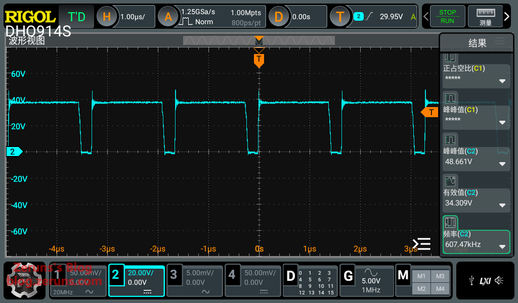
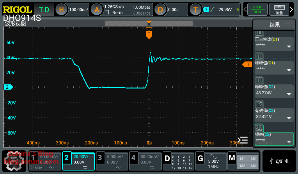
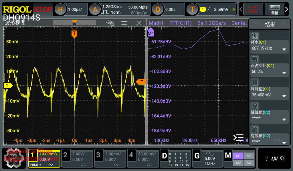
MOS驱动波形
输入侧(Buck部分)MOS上管栅极对地波形,开关频率607kHz,周期1.65微秒左右,米勒平台持续时间20nS左右,正常,驱动波形比较干净,没有振铃,过冲很小。
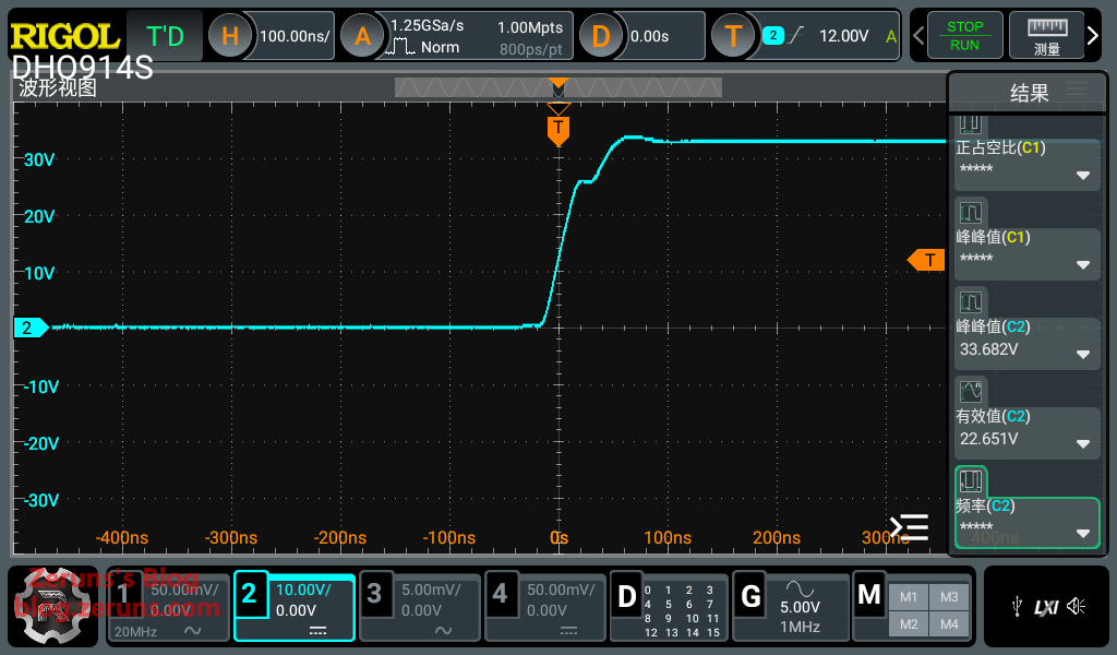
输出侧(Boost部分)MOS上管栅极对地波形,开关频率607kHz,周期1.65微秒左右,MOS开启时存在过冲和振铃,应该是驱动走线不合理的问题。
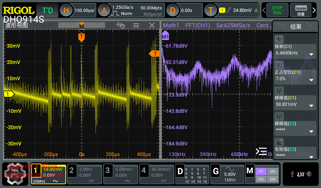
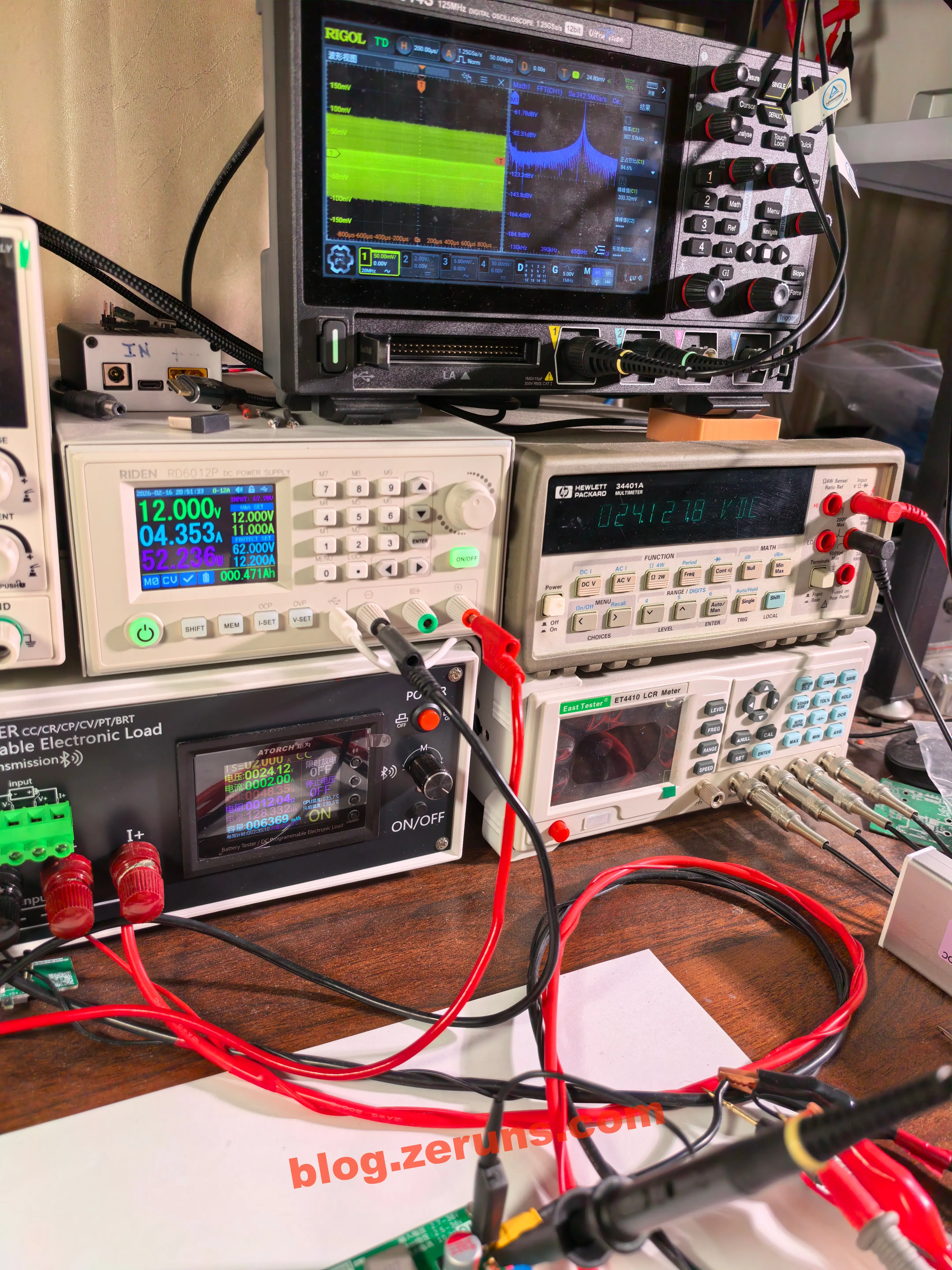
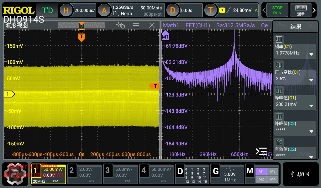
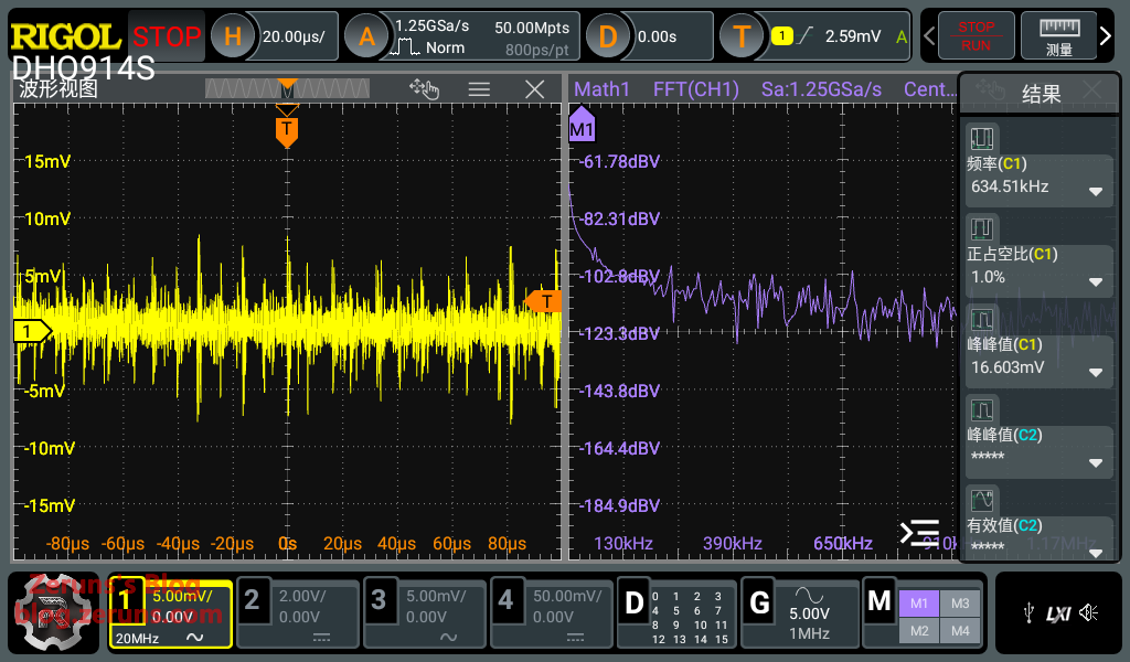
纹波测试
普源(RIGOL) DHO914S示波器 简单开箱评测:https://blog.zeruns.com/archives/764.html
输入12V,输出24V空载时,测得纹波峰峰值60mV左右。
输入12V,输出24V/2A时,测得纹波峰峰值200mV左右。
输入24V,输出5V空载时,测得纹波峰峰值16mV左右。
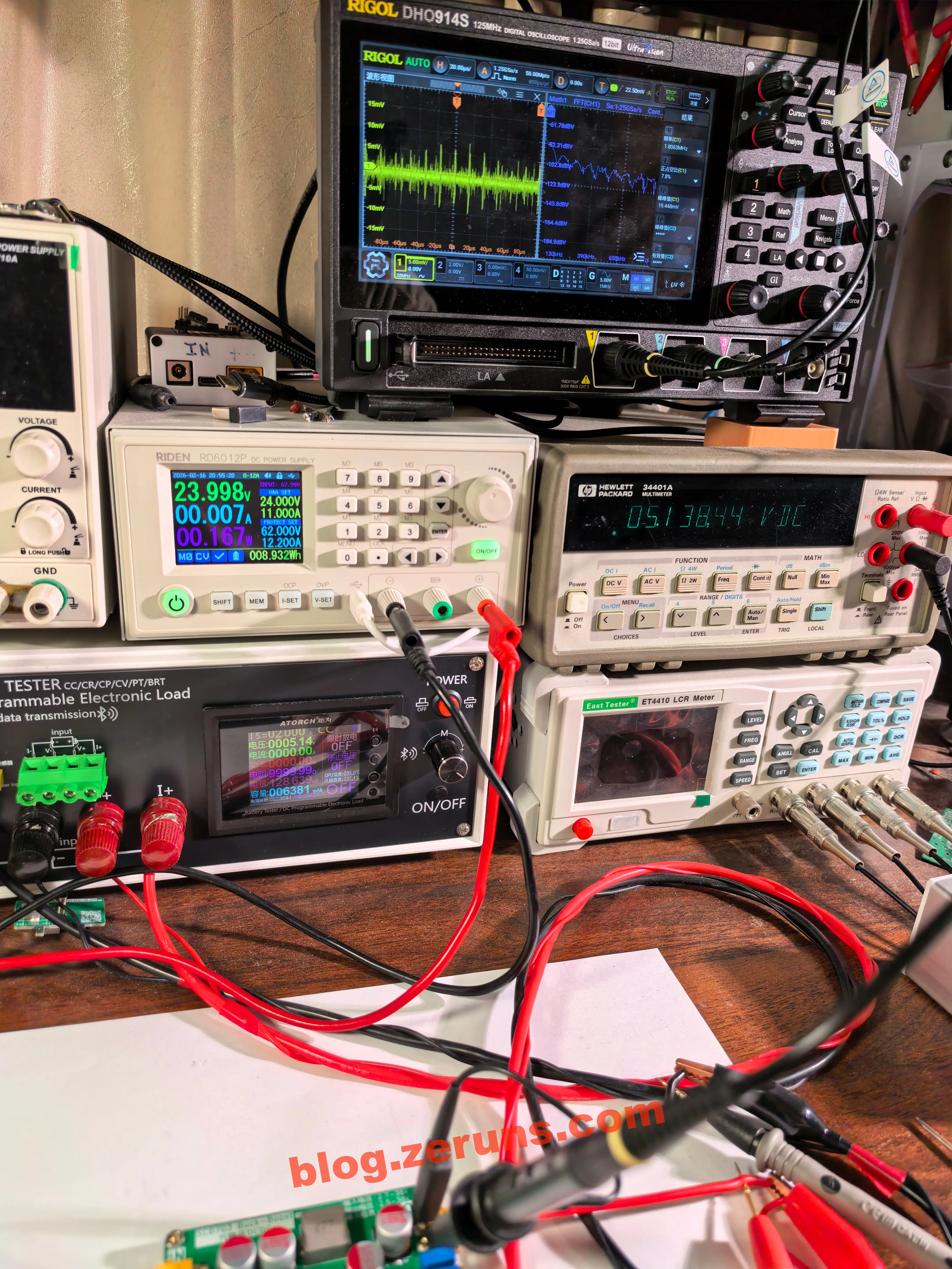
输入24V,输出5V/2A时,测得纹波峰峰值35mV左右。
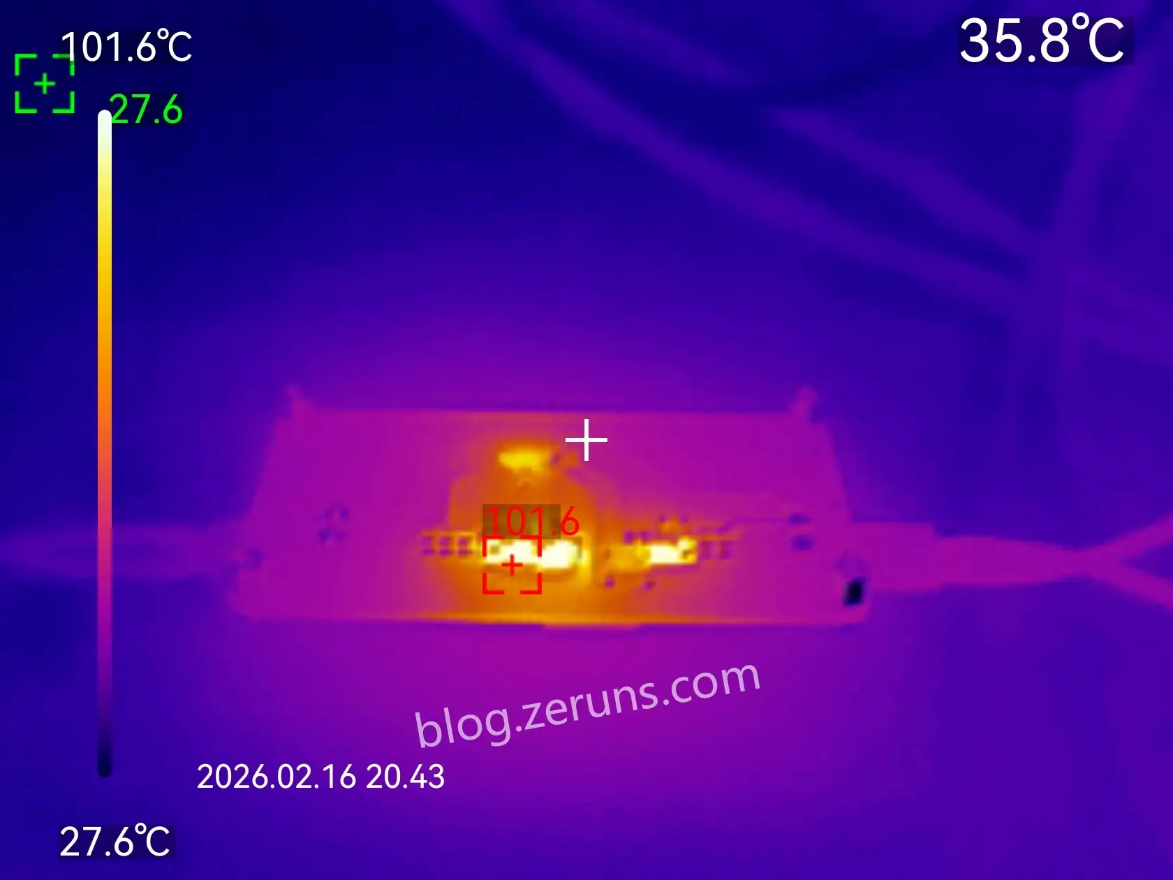
发热情况热成像
不加任何散热,输入36V,输出24V/9.5A时MOS管温度5秒升到100℃以上。底面热成像图如下。
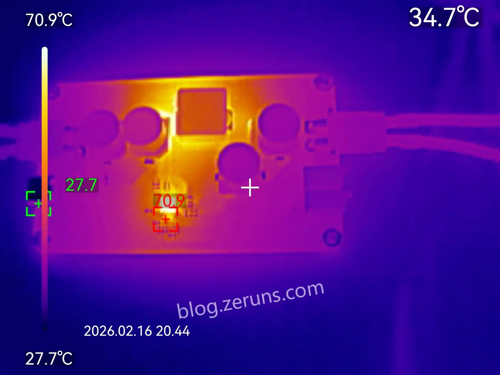
正面热成像图,SC8703芯片温度70度以上。
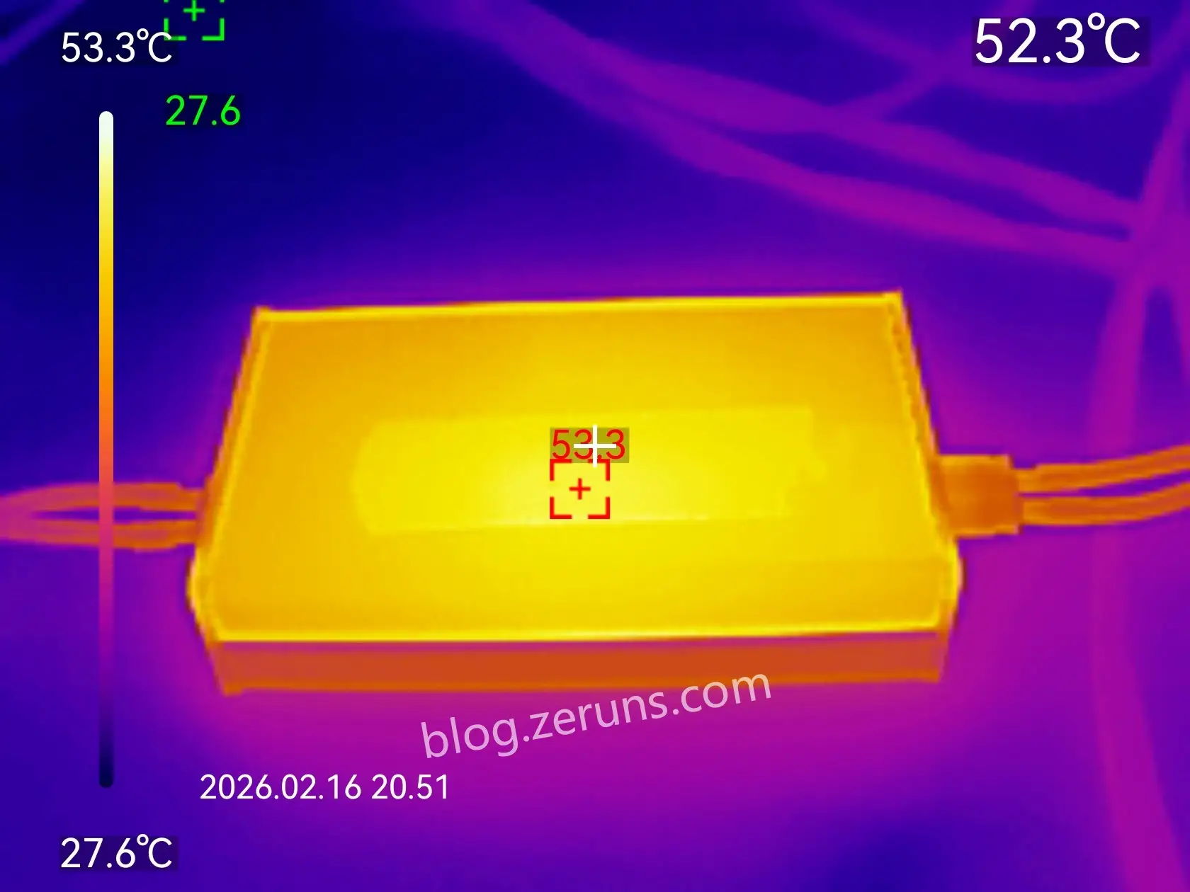
装上铝合金外壳后的热成像图,由于铝合金有点反光,避免影响测量结果所以在中间贴了个胶布,测得MOS管接触的那一面最高温度53℃左右。
资料下载地址
提供的资料有 KICAD项目文件、Gerber制板文件、详细BOM表(表里有元器件购买地址和价格)、顶层和底层拼一起的钢网文件、贴片丝印图、交互式BOM表(焊接辅助)、用到的芯片的数据手册文件、PCBA和外壳3D模型 等。
- Gitee开源地址:https://gitee.com/zeruns/sc8703_-buck-boost
- Github开源地址:https://github.com/zeruns/sc8703_-buck-boost
- 立创开源平台地址:https://oshwhub.com/zeruns/sc8703_buck-boost
- 华秋开源平台地址:https://p.eda.cn/d-1341729185952956416
- 123云盘下载地址:https://www.123865.com/s/2Y9Djv-I9ddH
开源项目推荐
- 做了个三相电量采集器开源出来,可以方便监测家里用电情况: https://blog.zeruns.com/archives/771.html
- 基于STM32的同步整流Buck-Boost数字电源 开源: https://blog.zeruns.com/archives/791.html
- LM25118自动升降压可调DCDC电源模块:https://blog.zeruns.com/archives/727.html
- 基于CH32V307的智能电子负载开源,嵌入式大赛作品开源: https://blog.zeruns.com/archives/785.html
- EG1151大功率同步整流可调升降压电源模块(支持TypeC PD快充输入)开源:https://blog.zeruns.com/archives/794.html
- 开源 140W+65W升降压PD3.1快充模块(2C+1A口),IP6557+IP6538,205W桌面充电器:https://blog.zeruns.com/archives/801.html
- 开源TypeC拓展坞,4个10Gbps的USBA口+2.5G网卡+读卡器:https://blog.zeruns.com/archives/868.html
- 【开源】24V3A反激式开关电源(基于UC3842,含电路和变压器参数计算过程):https://blog.zeruns.com/archives/910.html
推荐阅读
- 高性价比和便宜的VPS/云服务器推荐: https://blog.zeruns.com/archives/383.html
- 我的世界开服教程:https://blog.zeruns.com/tag/mc/
- GL-RM1PE 简单开箱测评和拆解,让普通电脑实现BMC远程管理功能:https://blog.zeruns.com/archives/900.html
- Discourse论坛搭建教程,零基础部署Discourse开源社区论坛网站:https://blog.zeruns.com/archives/919.html
- OWON HDS160 示波万用表 简单开箱测评和拆解:https://blog.zeruns.com/archives/927.html
- 我的世界一键快速开服教程,支持各个MC版本(forge、fabric、paper、基岩 等等):https://blog.zeruns.com/archives/923.html