LADIS D1500 Uninterruptible Power Supply (UPS) Teardown Analysis
The UPS in my home network cabinet broke down, and the battery seems unable to charge. When disconnected from mains power, there’s no output directly, and even with the load disconnected, it can only provide output for a short time at no load. The battery is likely faulty. I discovered the problem just after the one-year warranty period expired. I’ve purchased two LADIS UPS units, and the earlier one also experienced poor battery runtime, with battery backup reduced to less than 5 minutes. Fortunately, I discovered the issue one month before the warranty expired and applied for a replacement on JD.com. It seems that LADIS UPS batteries degrade very quickly.
Teardown video: https://www.bilibili.com/video/BV1dy411b77e/
Testing and teardown of a 120W charger from Douyin Mall for 2.6 yuan: https://blog.zeruns.com/archives/786.html
Specifications
- Model: D1500
- Capacity: 1500VA/900W
- Input Voltage Range: 145~290VAC
- Power Factor: ≥0.99 @Rated Voltage (100% Load)
- Output Voltage Range (Mains Mode): 195~255VAC
- Output Frequency Range (Battery Mode): 50Hz ± 0.5Hz
- Output Waveform (Battery Mode): Square Wave
- Conversion Time: ≤10ms
- Battery Model: 12V/9AH
- Battery Quantity: 2 units
- Charging Time: 10 to 16 hours
- Dimensions: Length × Width × Height 320×120×190mm
- Weight: 11kg
Purchase Links:
- LADIS D1500: https://u.jd.com/xsJjvIr
- Schneider BK650M2: https://u.jd.com/xiJZA8x
- Huawei 1KTTS-1KVA/800W: https://u.jd.com/xqJoSOJ
Teardown
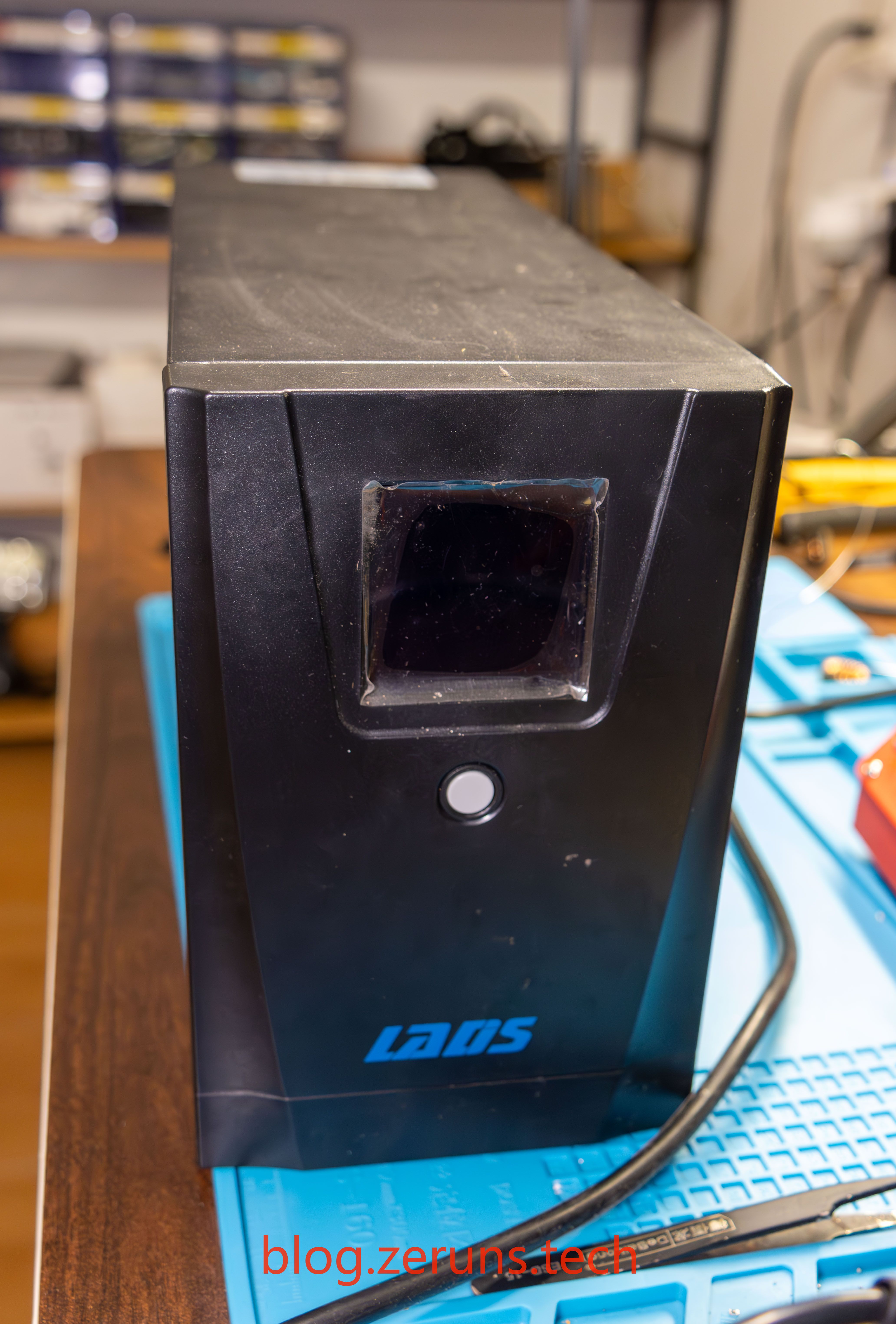
Front
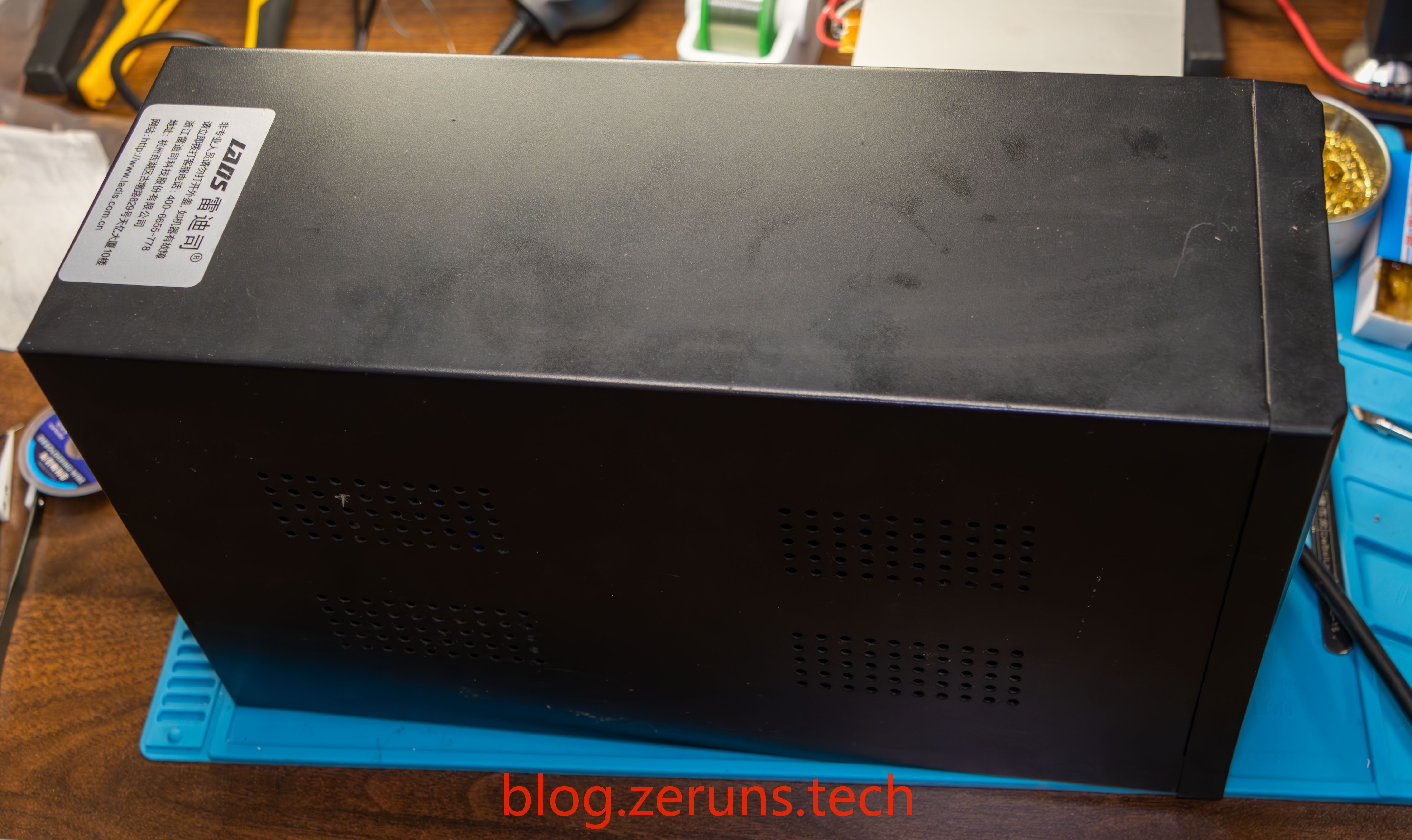
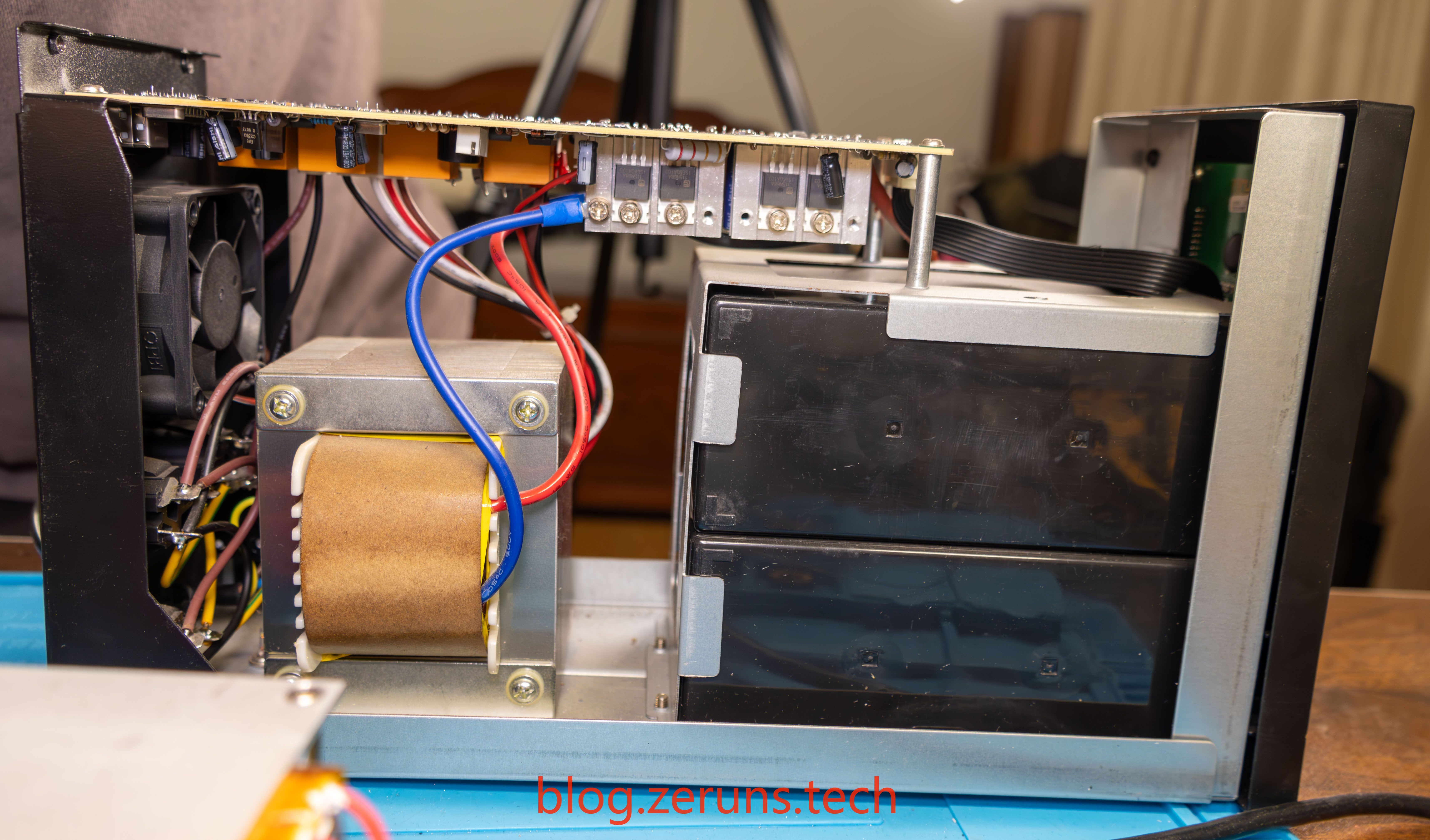
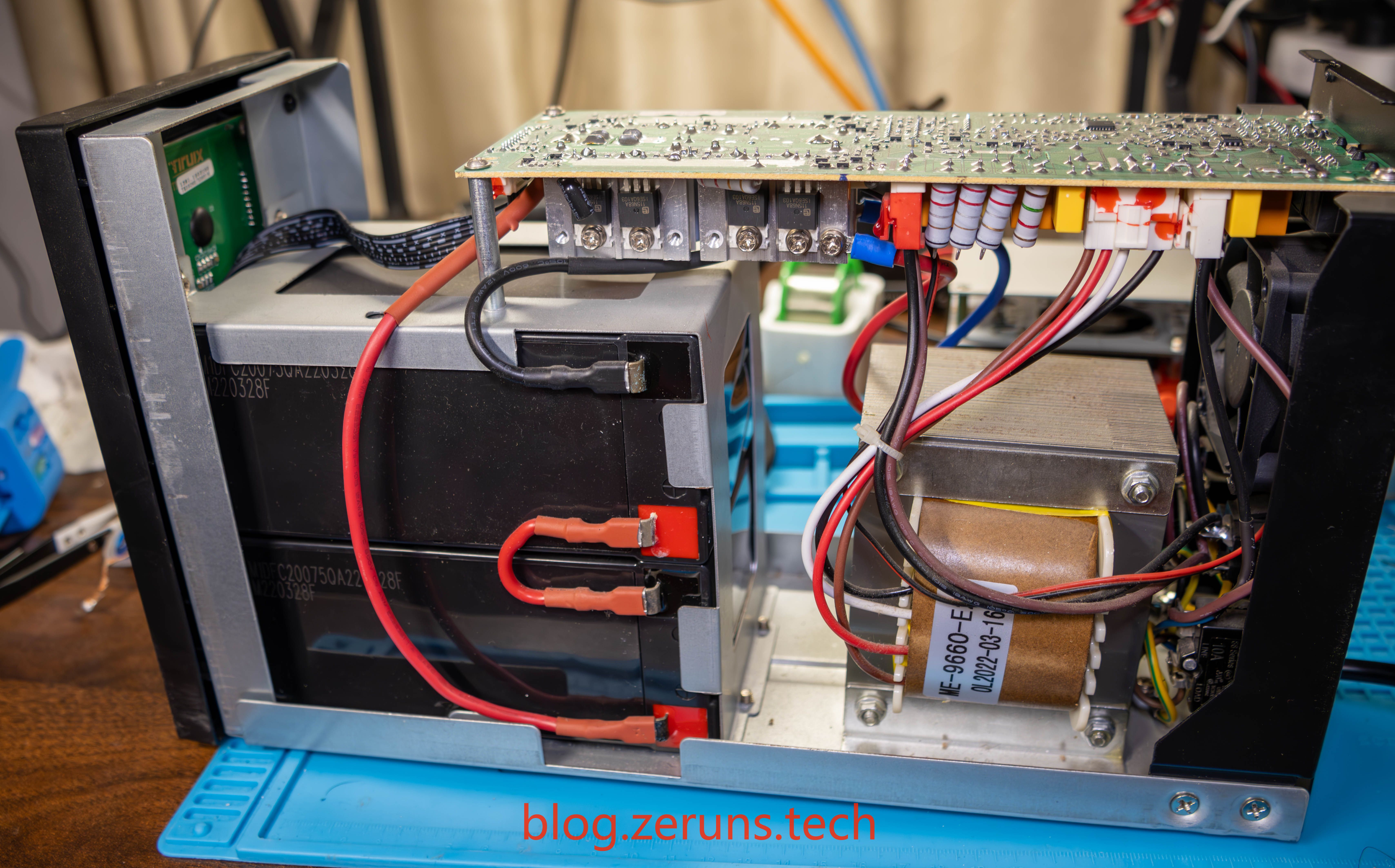
Side
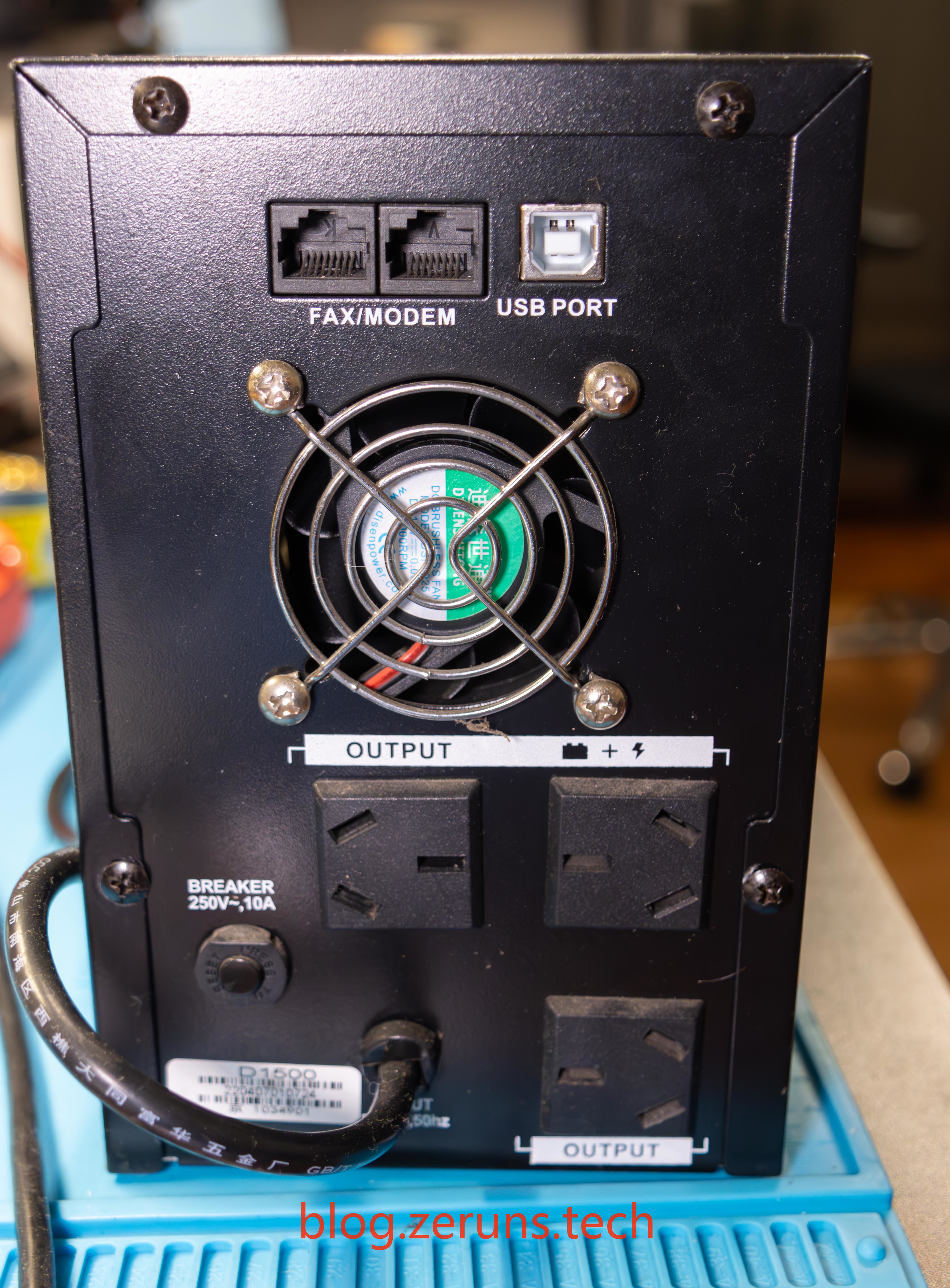
Back
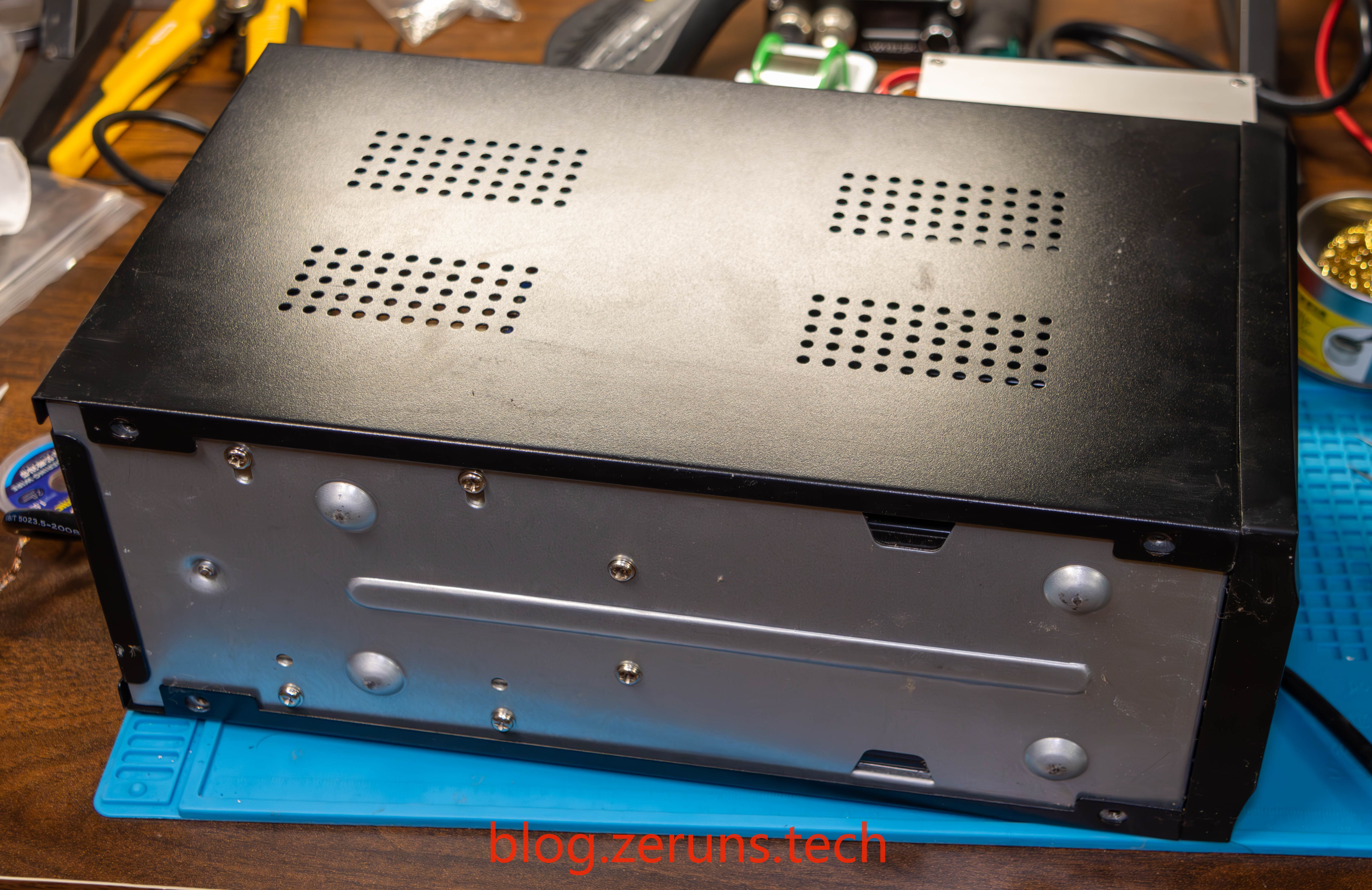
Bottom
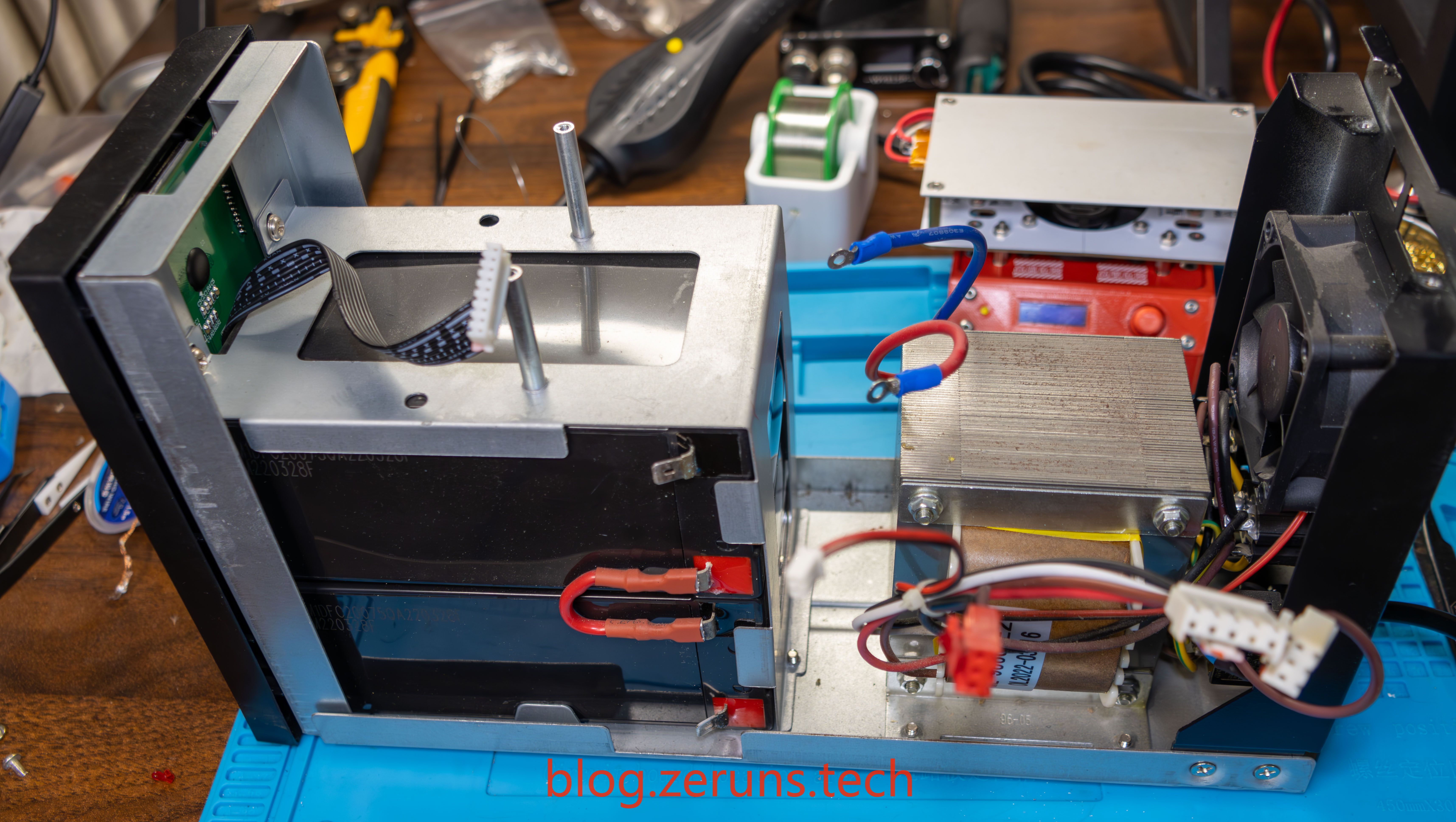
Side view after opening the cover. Below is a transformer and two 12V 9AH lead-acid batteries connected in series. Above is the circuit board.
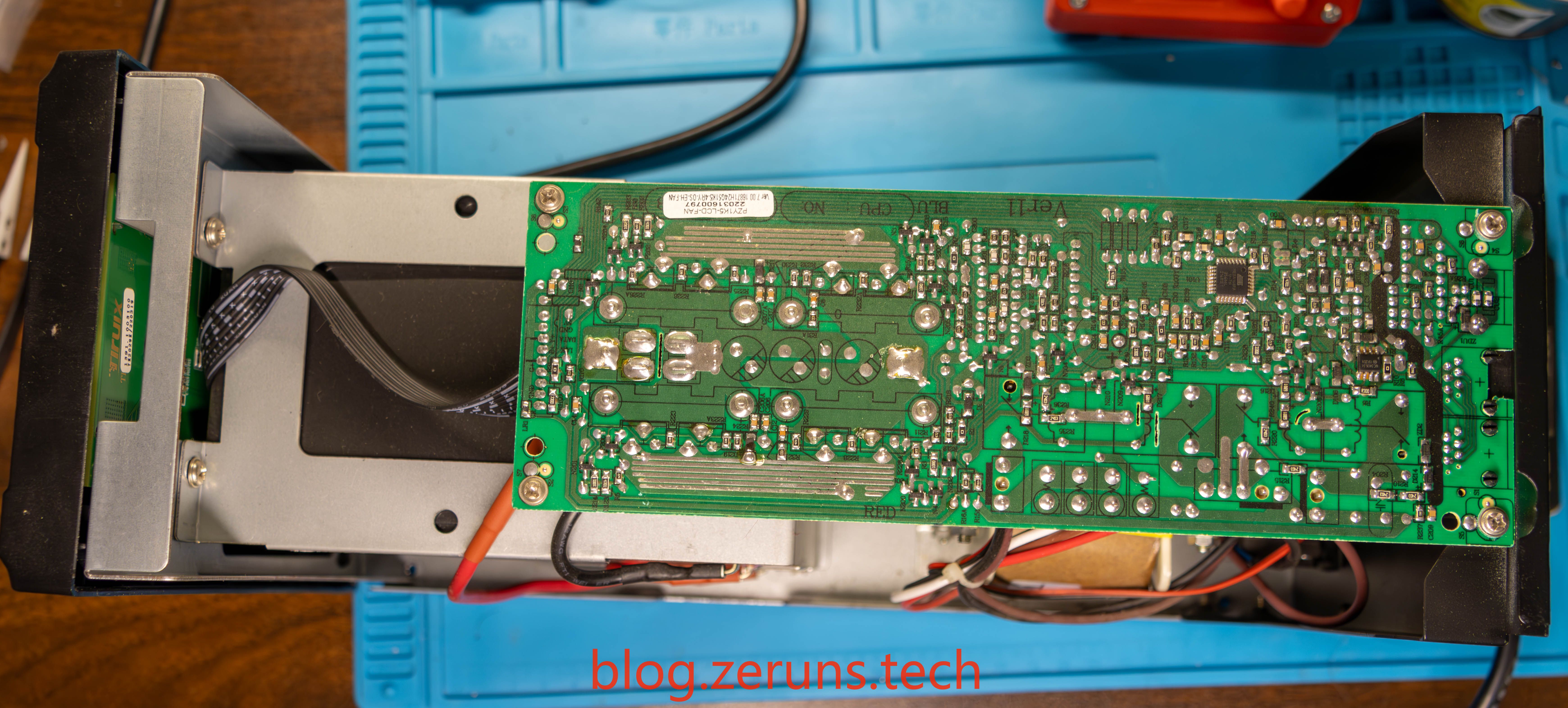
Top view after disassembly
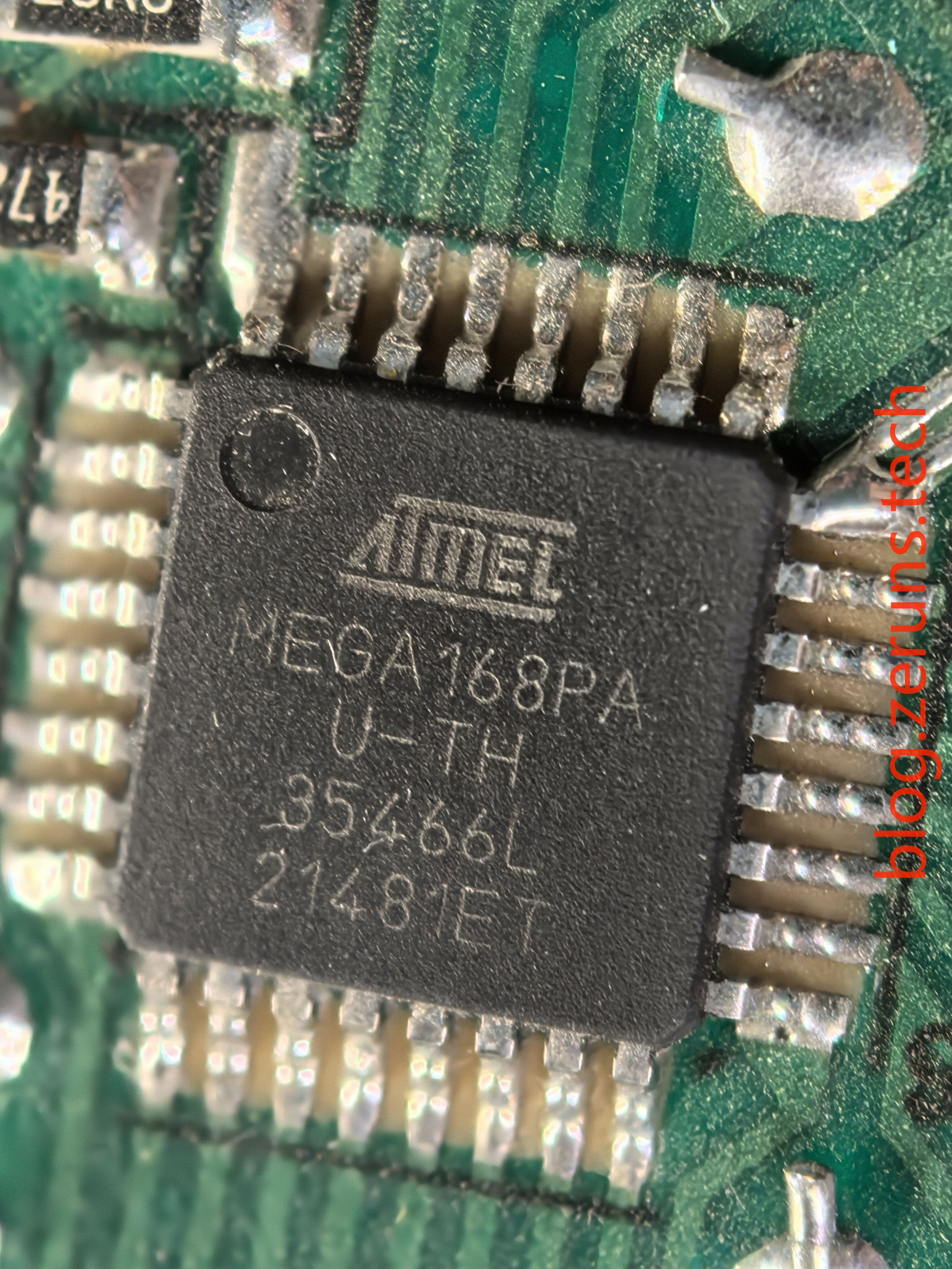
The main control chip is an ATmega168PA, an 8-bit microcontroller.
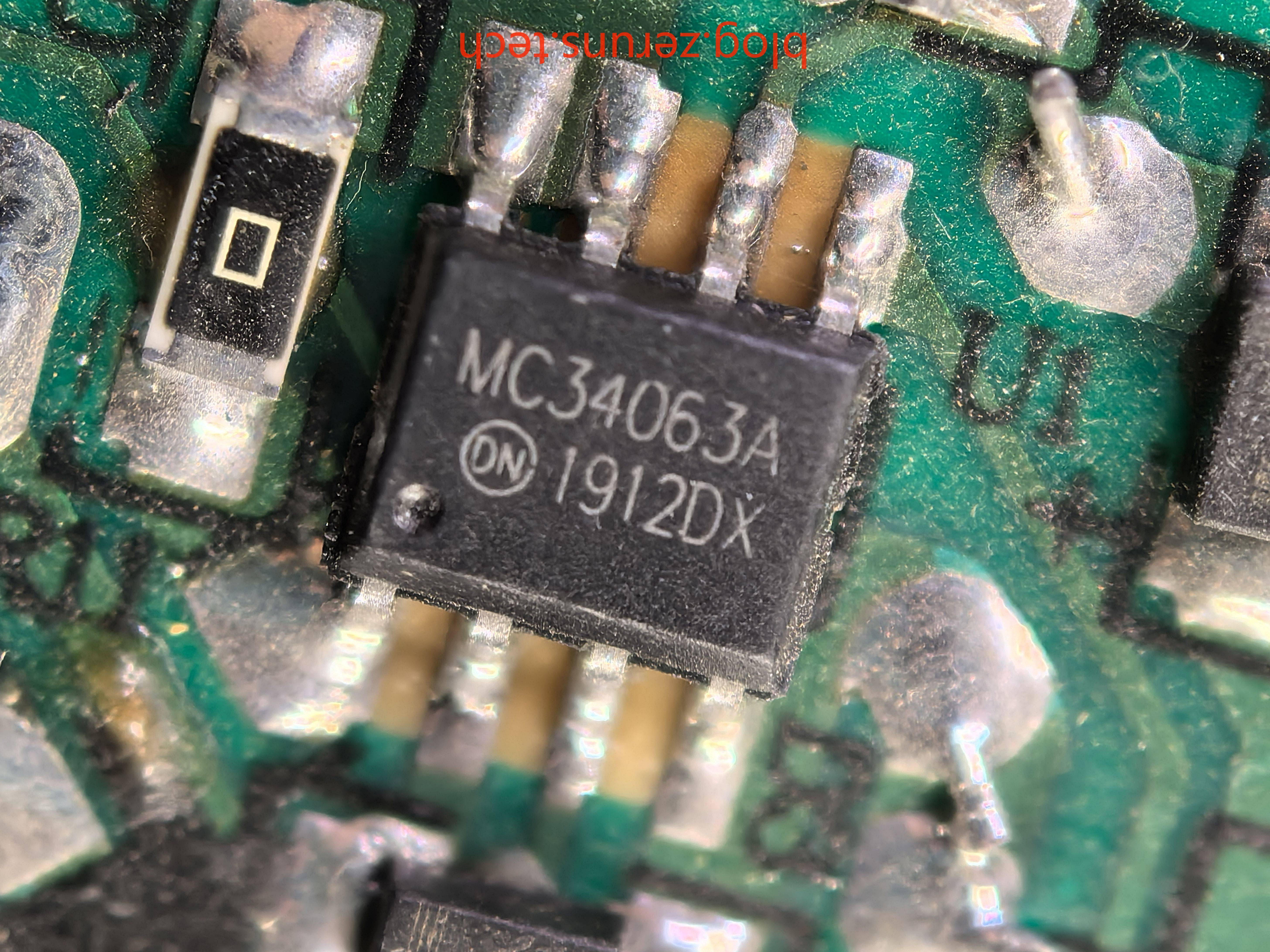
Next to it is an MC34063A DCDC buck converter chip, which should supply power to the microcontroller and relay.
Circuit board front
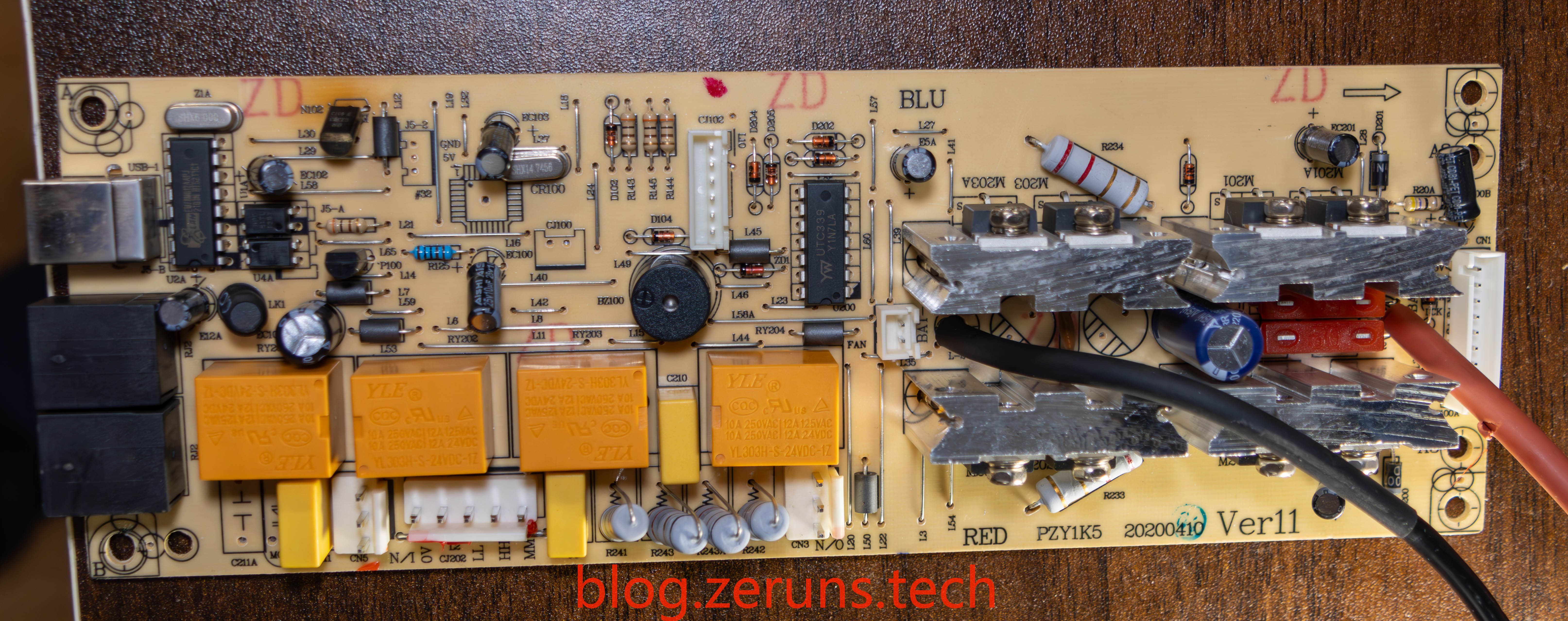
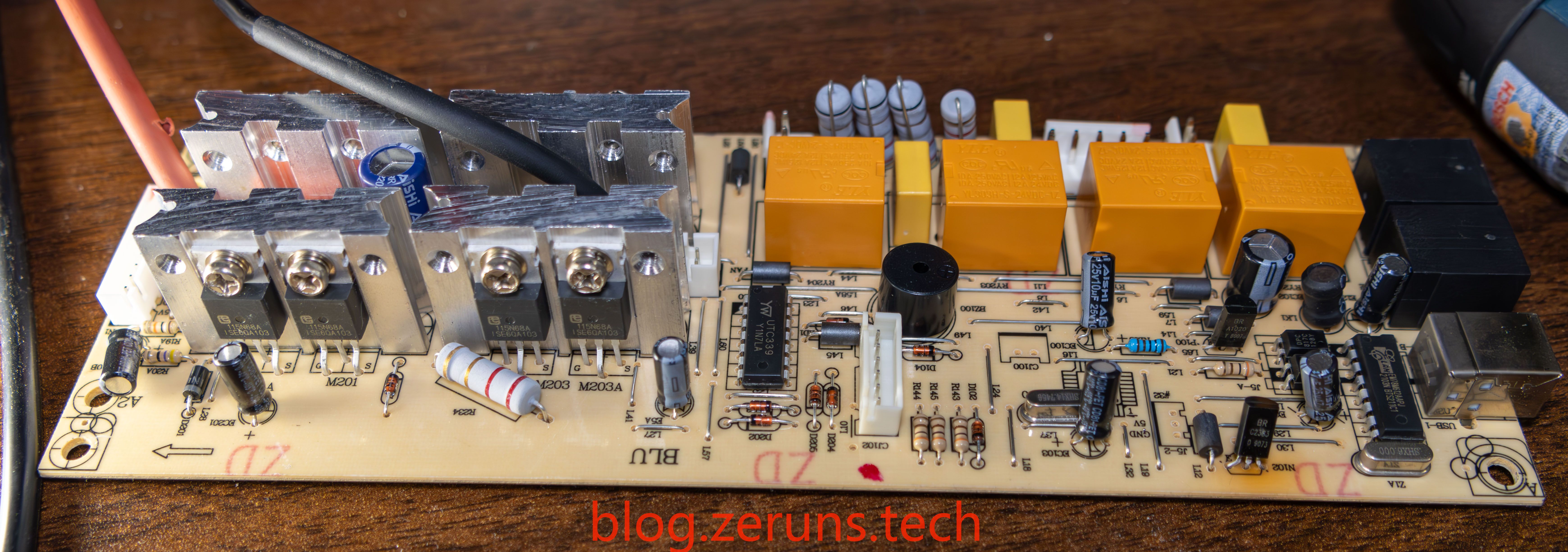
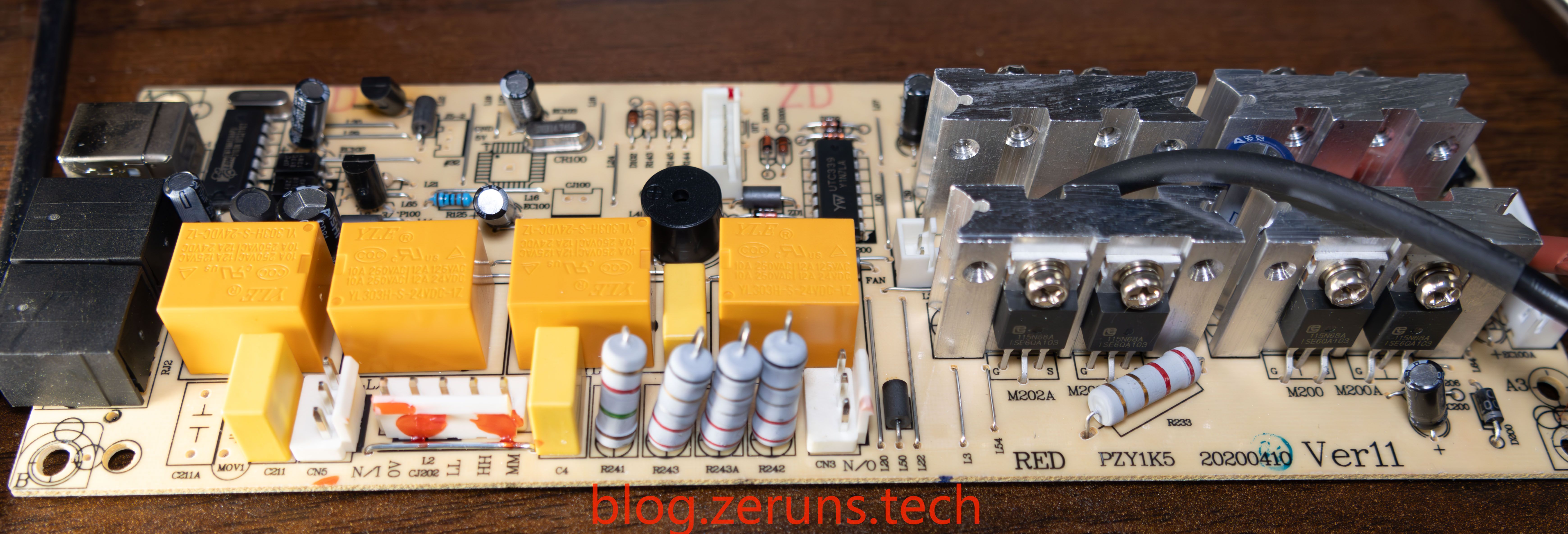
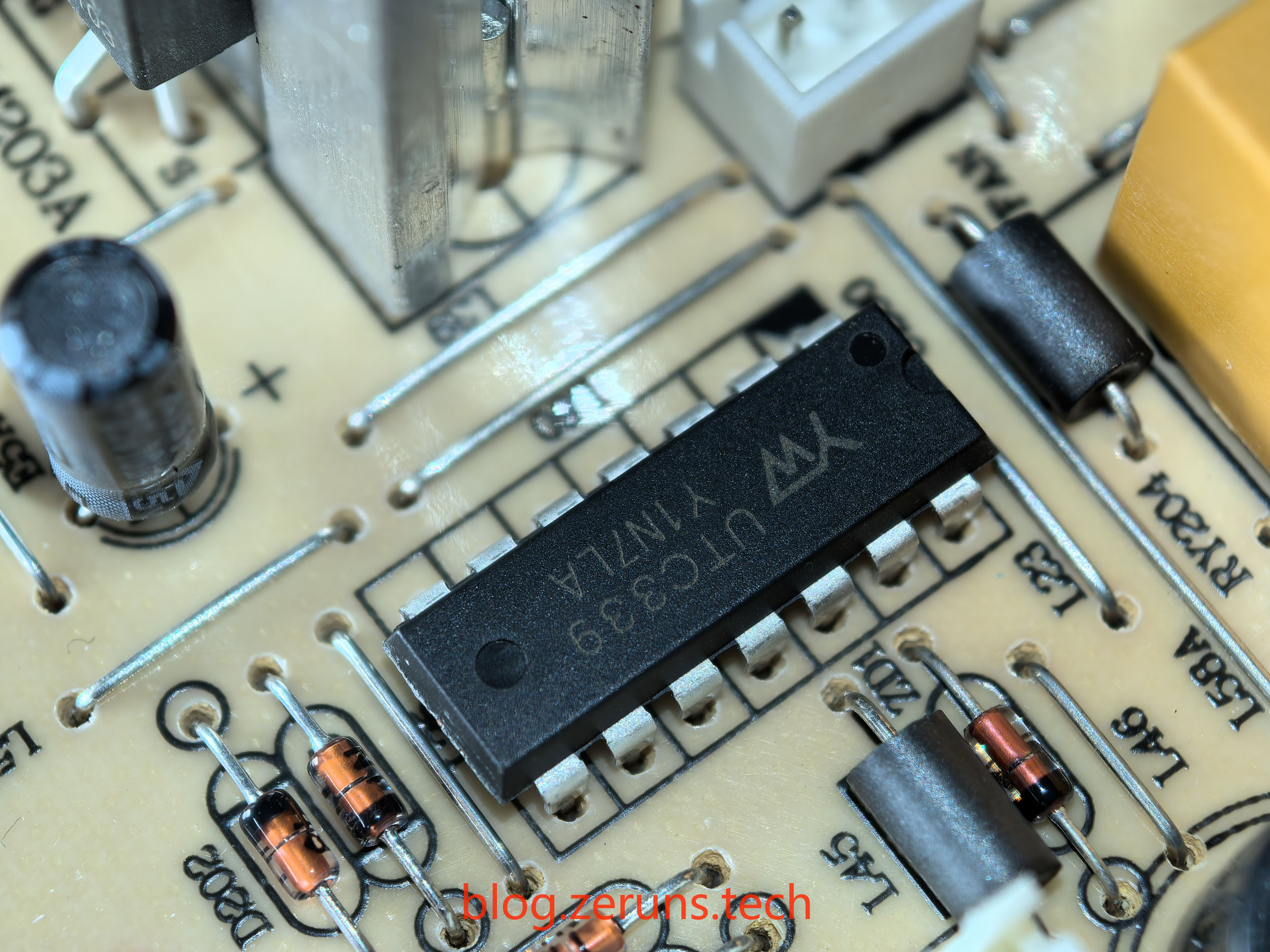
UTC339 chip, a four-channel voltage comparator.
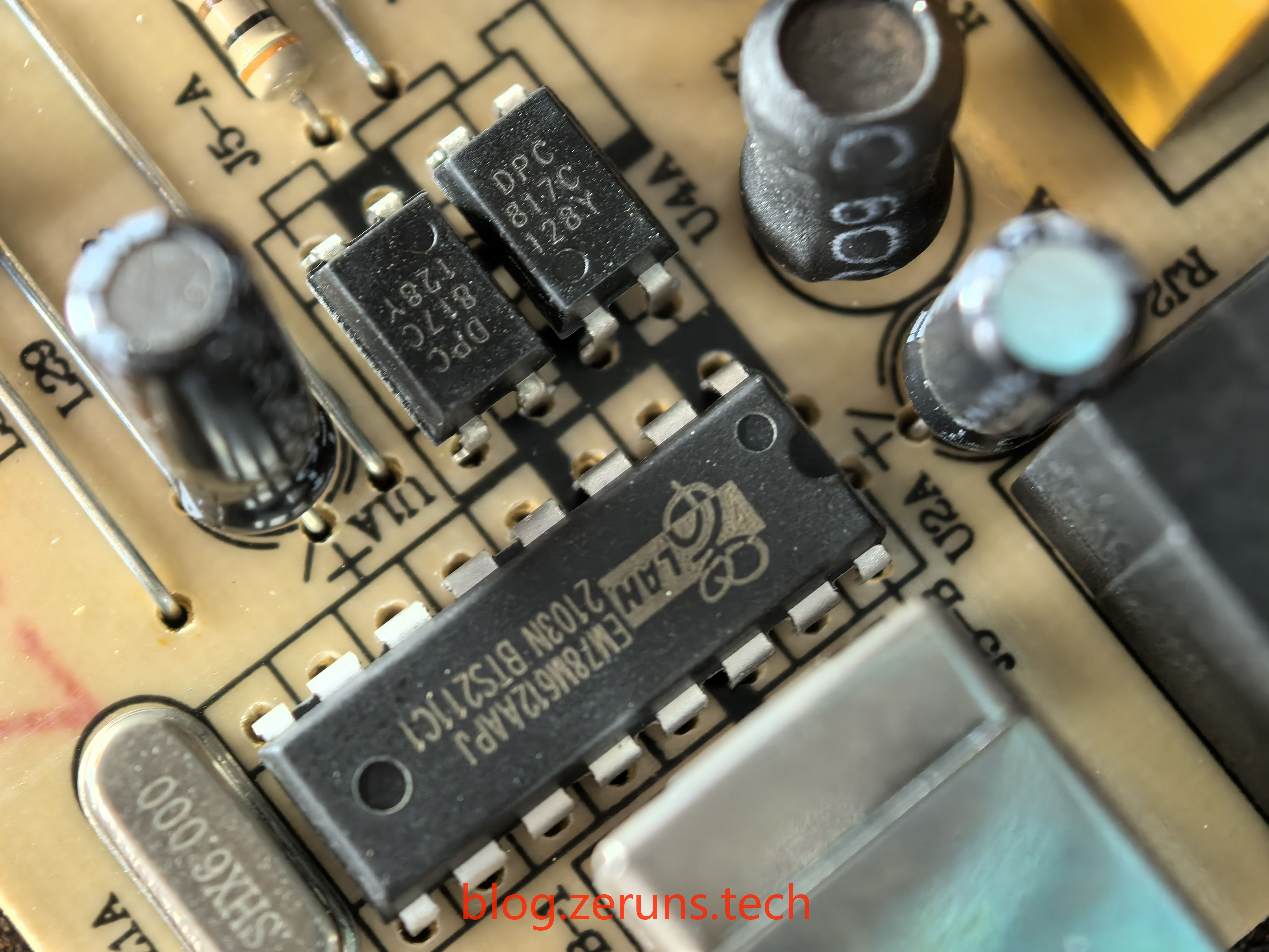
The EM78M612AAPJ is a microcontroller manufactured by Elan Microelectronics Corporation, belonging to the EM78M612 series. This series is based on an 8-bit RISC architecture universal serial bus (USB) microcontroller suitable for low-speed USB device applications. This microcontroller is widely used in electronic devices or systems requiring serial communication capabilities, particularly in USB device applications, where it can automatically identify and decode standard USB commands, thereby simplifying USB device firmware design.
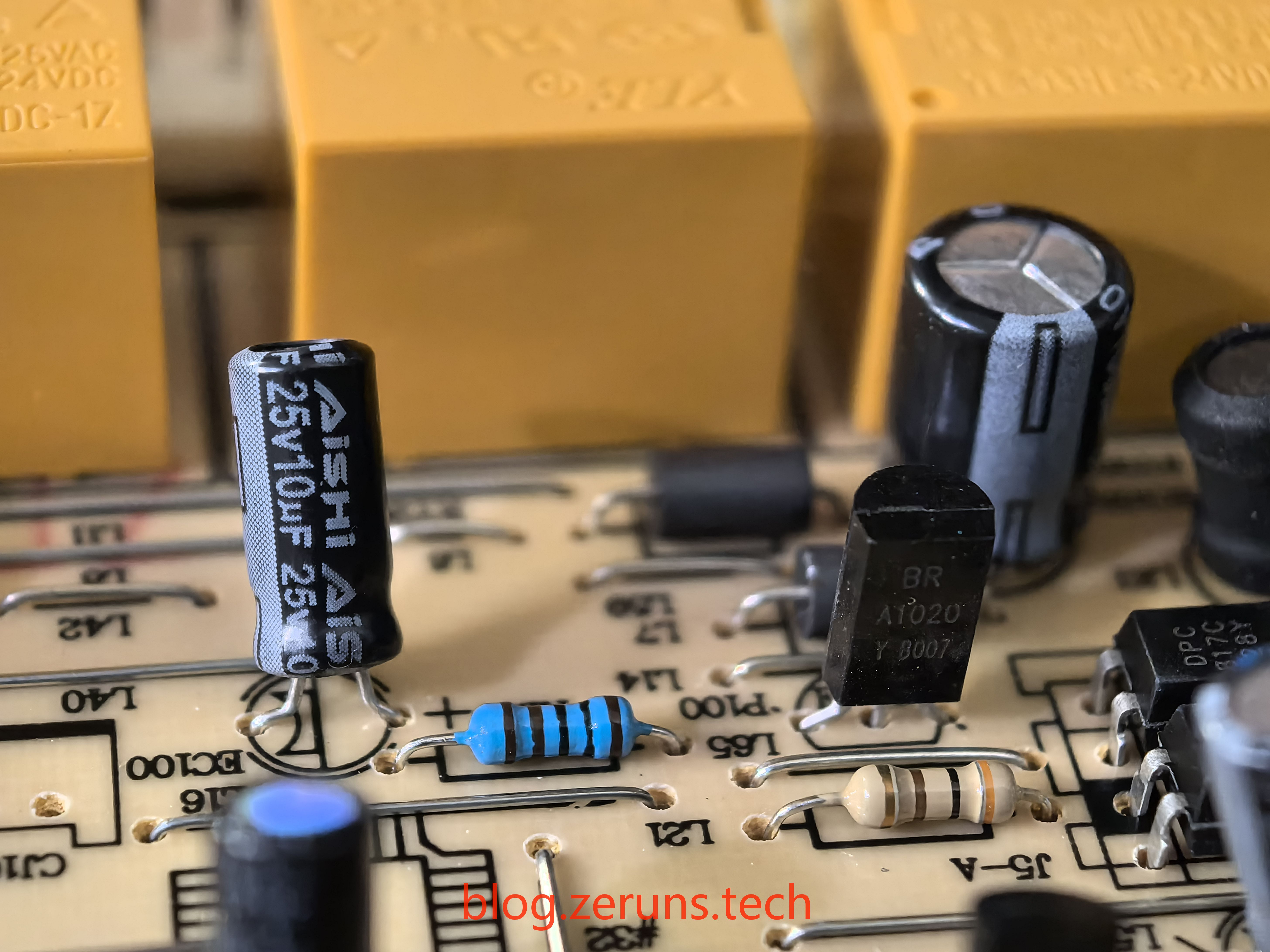
The capacitor brands on the circuit board are all AISHI (Aihua).
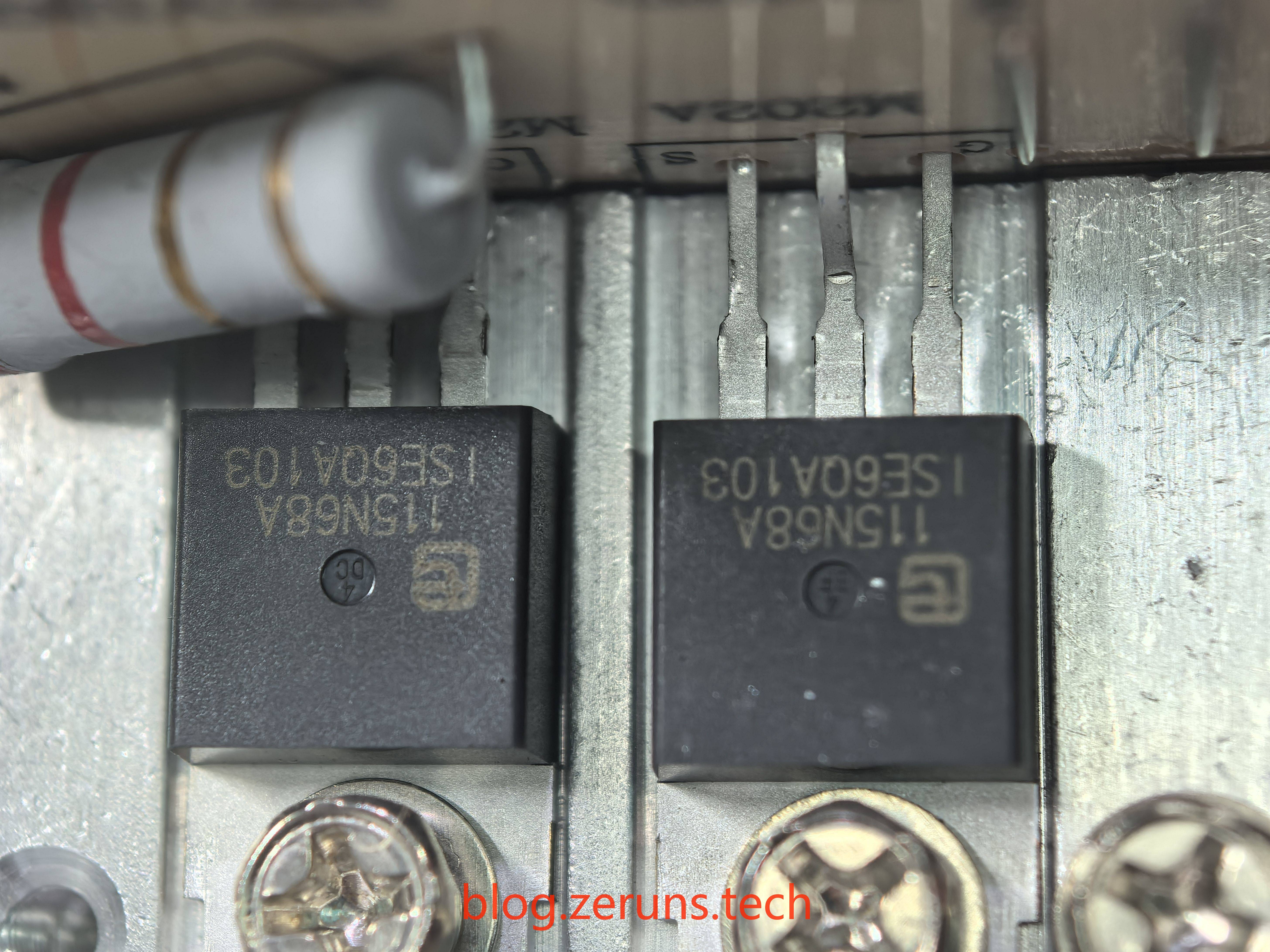
The MOS transistor is a Wuxi Ziguang Micro 115N68A with parameters of 68V 115A.
After removing the inverter circuit board
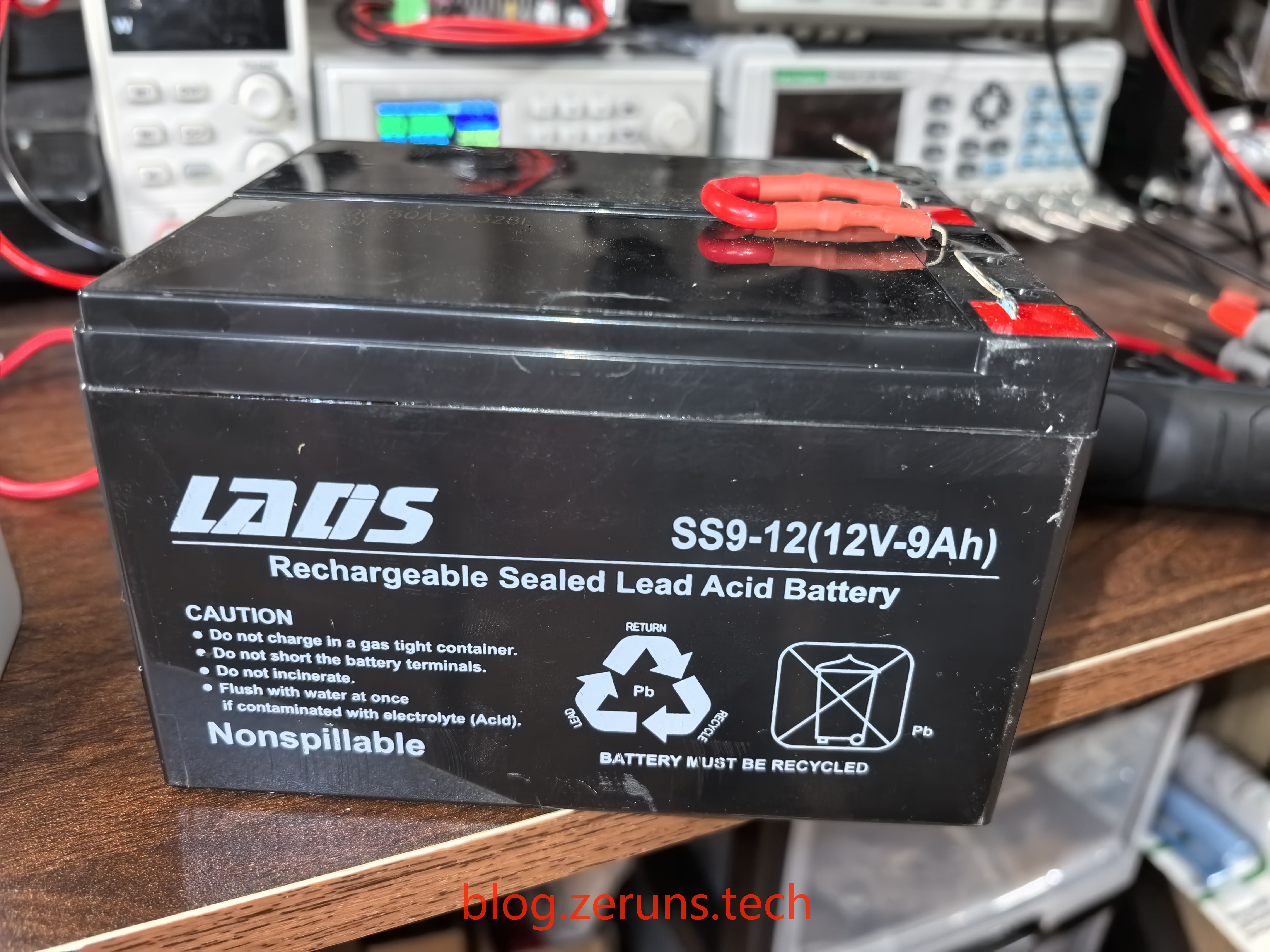
Battery brand is LADS, model SS9-12, 12V 9AH lead-acid battery, two connected in series.
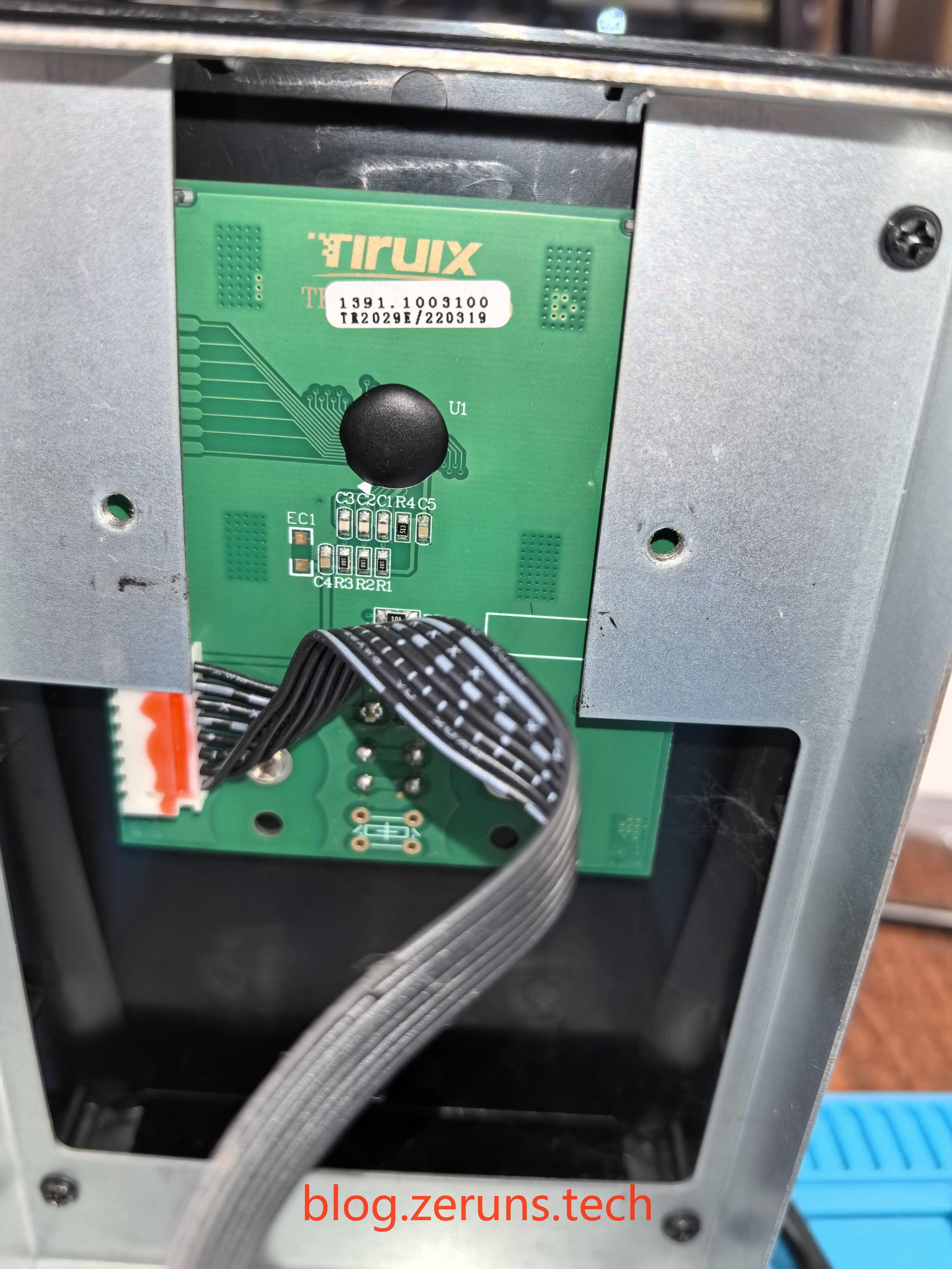
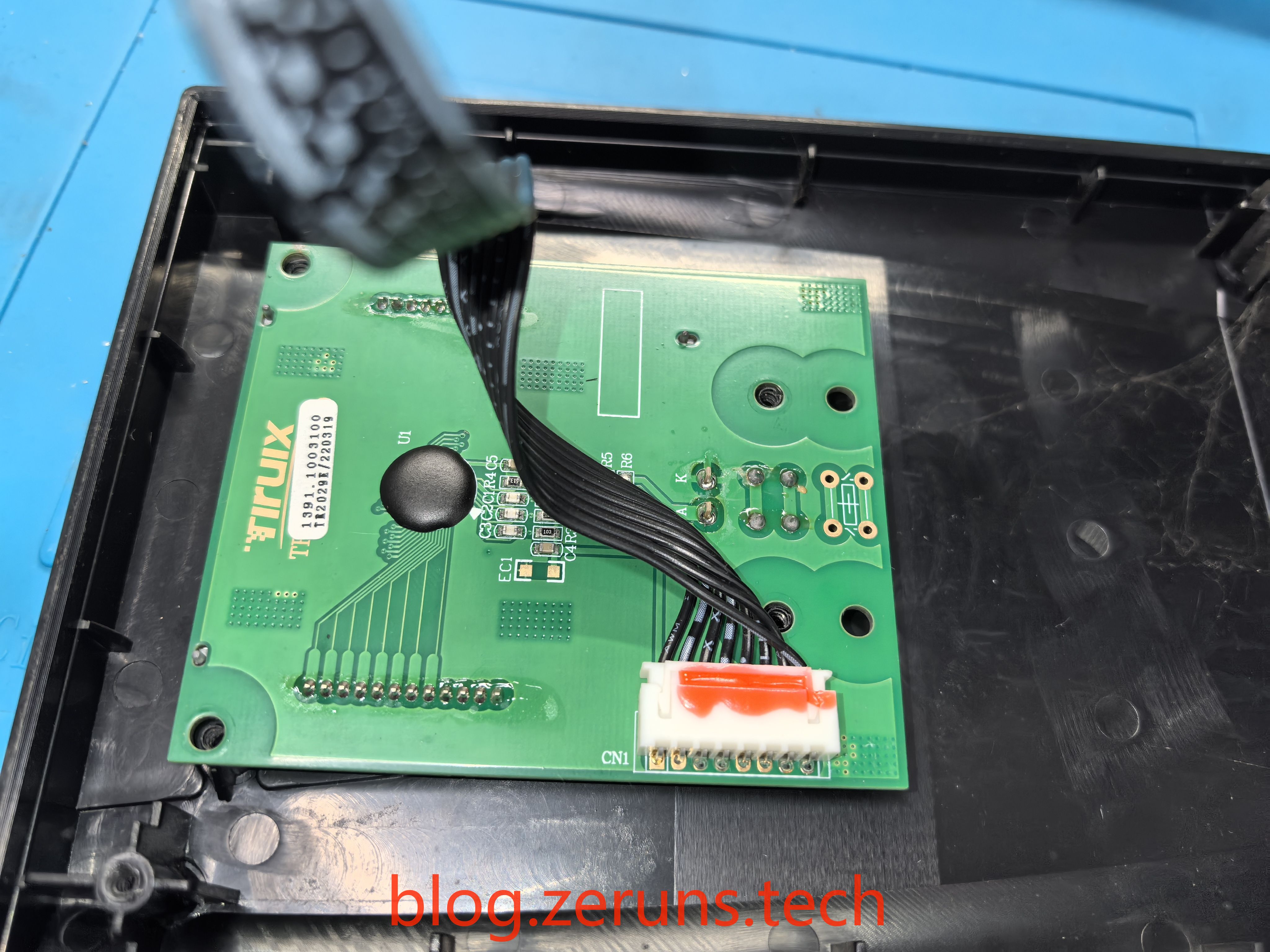
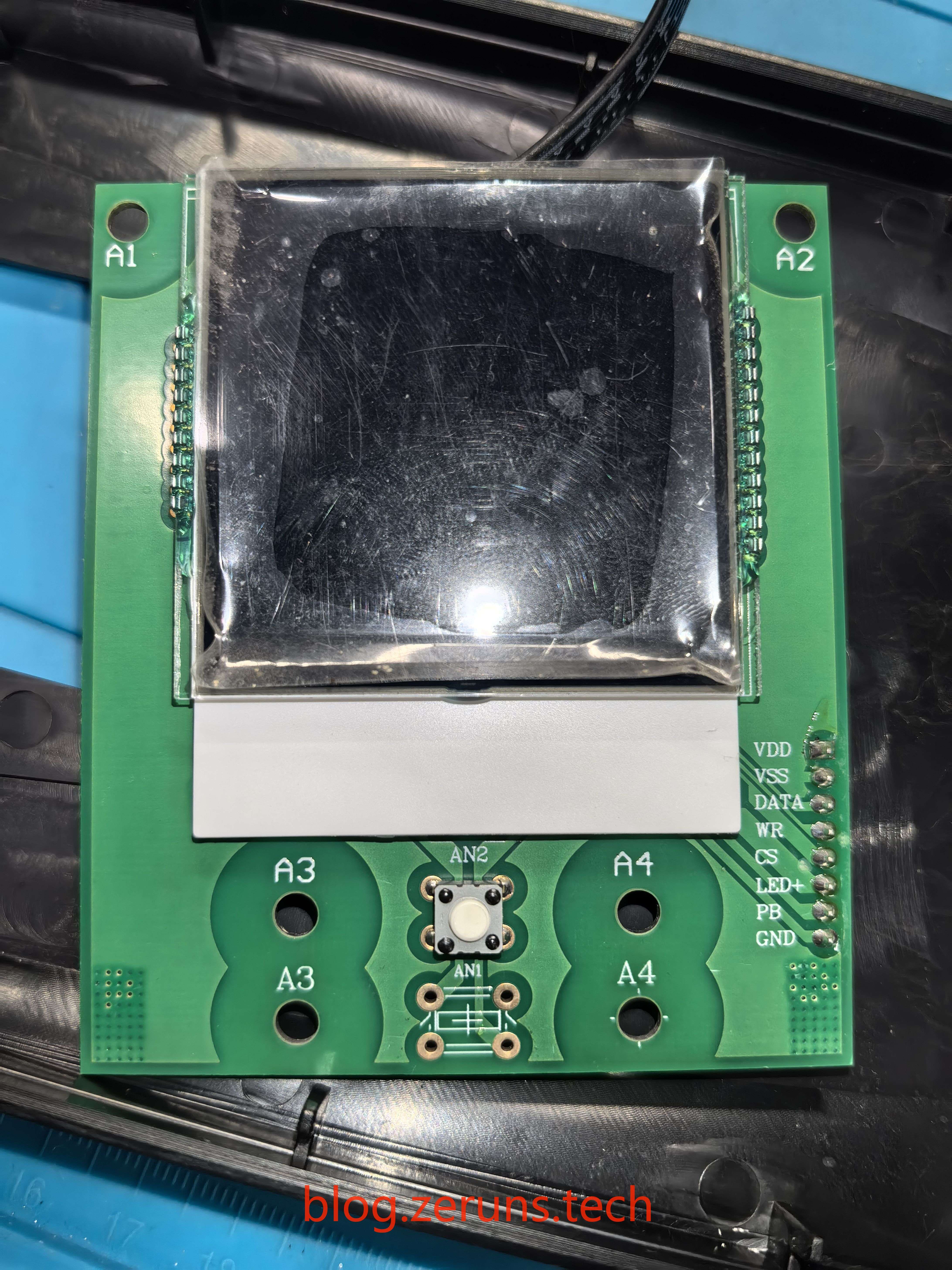
LCD display circuit board on the front
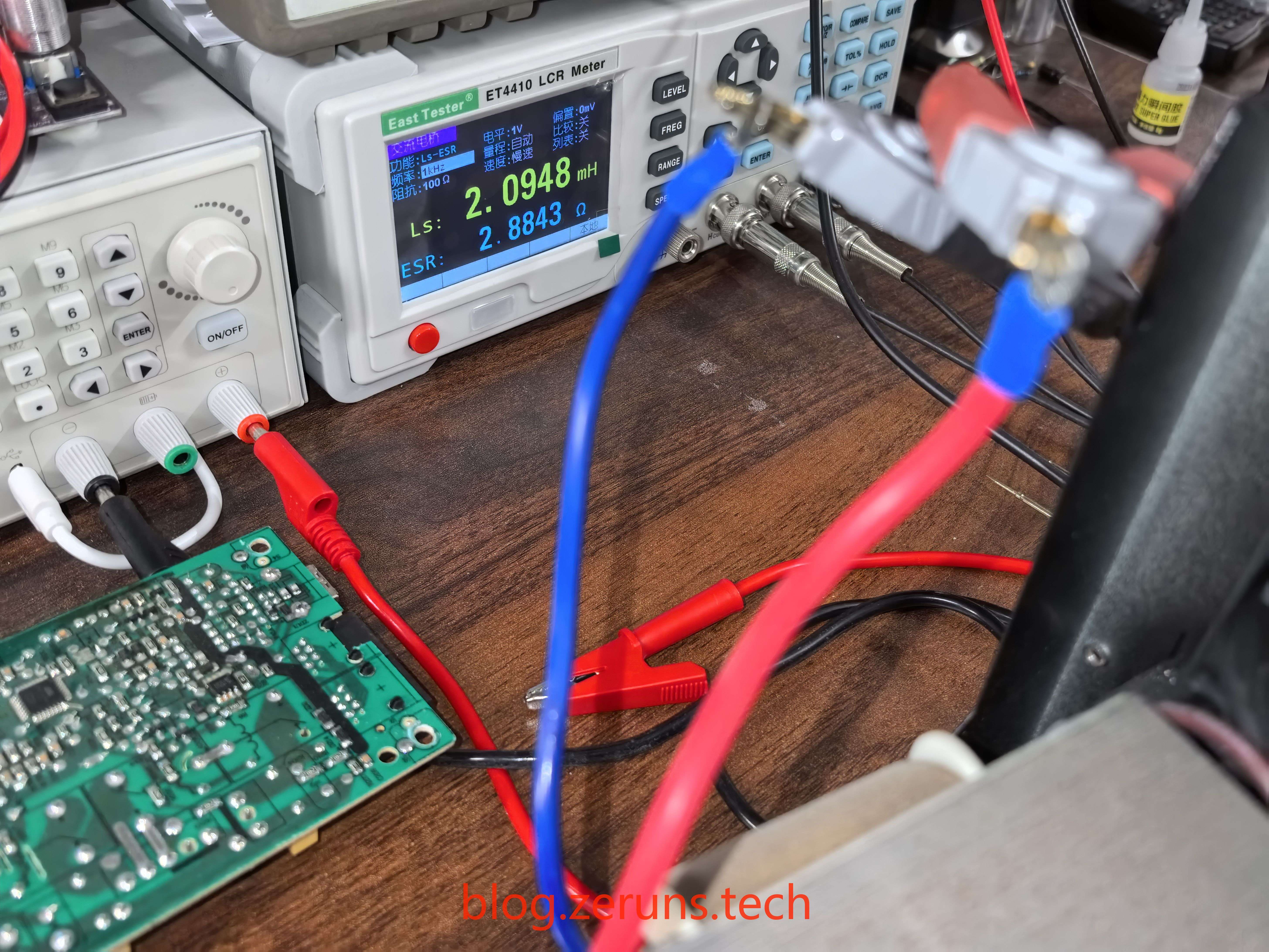
Using an LCR meter, the inductance of the transformer primary coil is measured to be 2.0948mH.
Analysis
Electronics/Microcontroller Technology Exchange QQ Group: 2169025065
After examining the circuit traces, I roughly sketched the inverter section of this UPS. It’s just a general circuit diagram without detailed components and control sections.
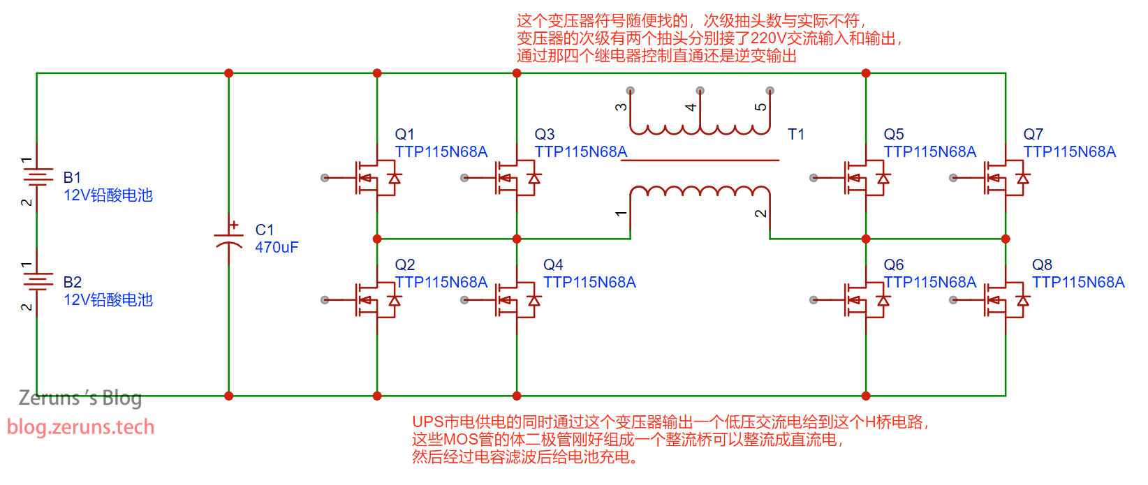
This UPS inverter appears to be a line-frequency inverter, which uses MOS transistors to form an H-bridge circuit. PWM signals control these MOS transistors to generate a 50Hz square wave low-voltage AC signal that is stepped up to 220V AC through a line-frequency transformer.
(The basic principle of a high-frequency inverter is to first boost to around 400V through DCDC conversion, then use SPWM waves to control MOS transistors to generate a high-frequency AC signal, which is then filtered through an LC filter composed of inductors and capacitors to produce a low-frequency AC signal for inversion. The conversion efficiency is much higher than line-frequency inverters. My description may not be entirely accurate, so take it with a grain of salt. Experts are welcome to explain in the comments.)
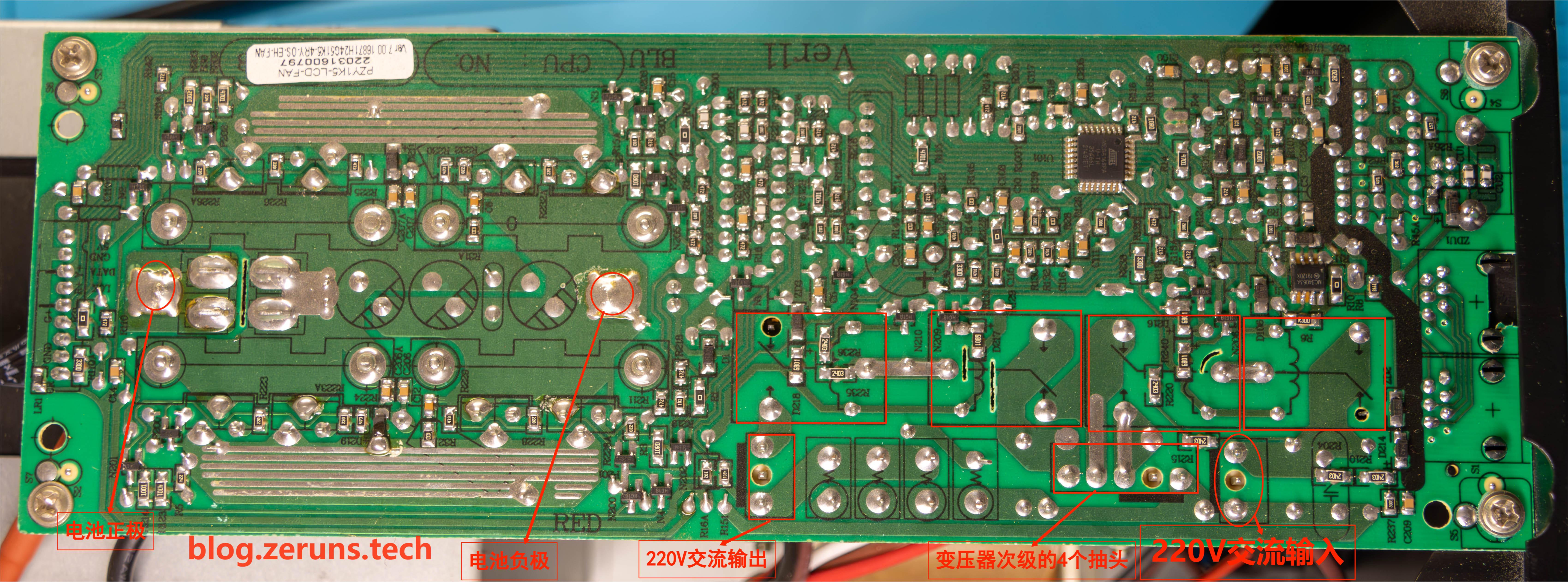
The secondary of this line-frequency inverter has 4 taps, controlled by 4 relays to achieve functions such as: mains direct output, mains charging the battery, and battery inverter output. You can see the PCB images below where I’ve marked various interfaces.
When the UPS is powered by mains, it simultaneously outputs a low-voltage AC signal through this line-frequency transformer to the H-bridge circuit (at this point, the primary and secondary of the transformer are effectively reversed). The body diodes of the MOS transistors in the H-bridge circuit form a rectifier bridge that rectifies to DC, which is then filtered by capacitors to charge the battery.
This circuit is essentially a bidirectional AC-DC converter.
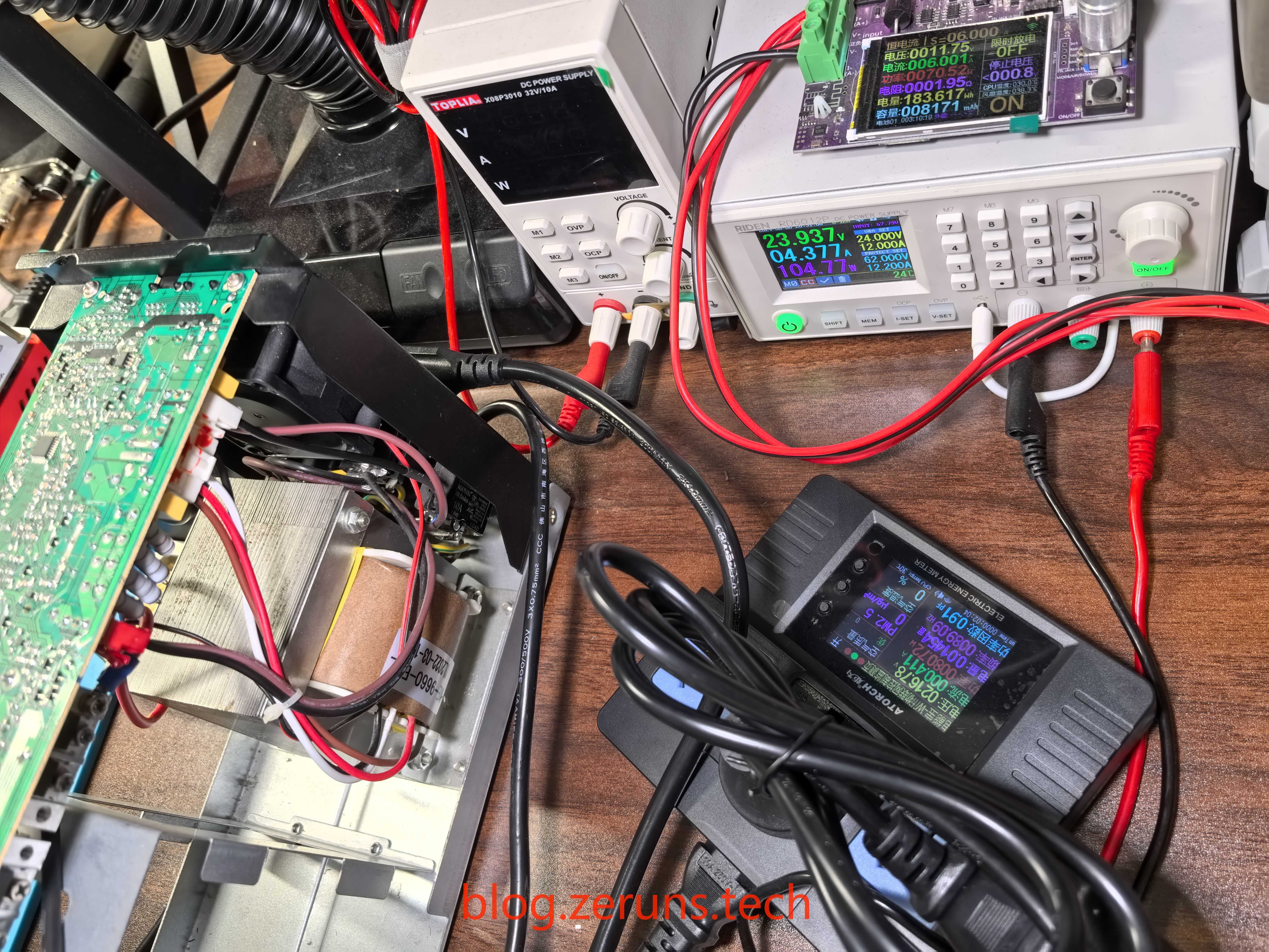
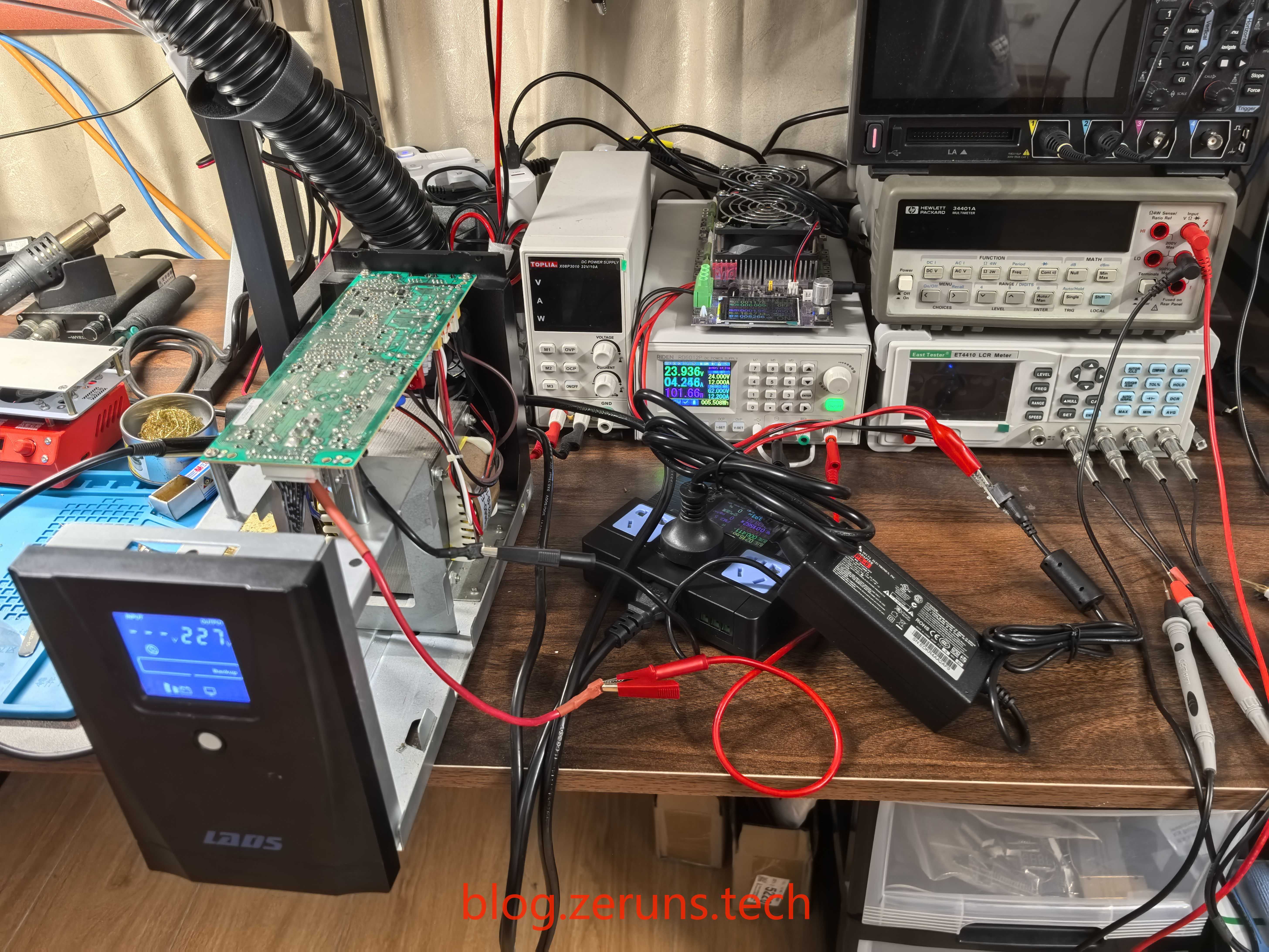
The two battery lines of the UPS are connected to an adjustable power supply set to output 24V. The UPS is turned on for output, with no-load power consumption around 18 watts, which is slightly high.
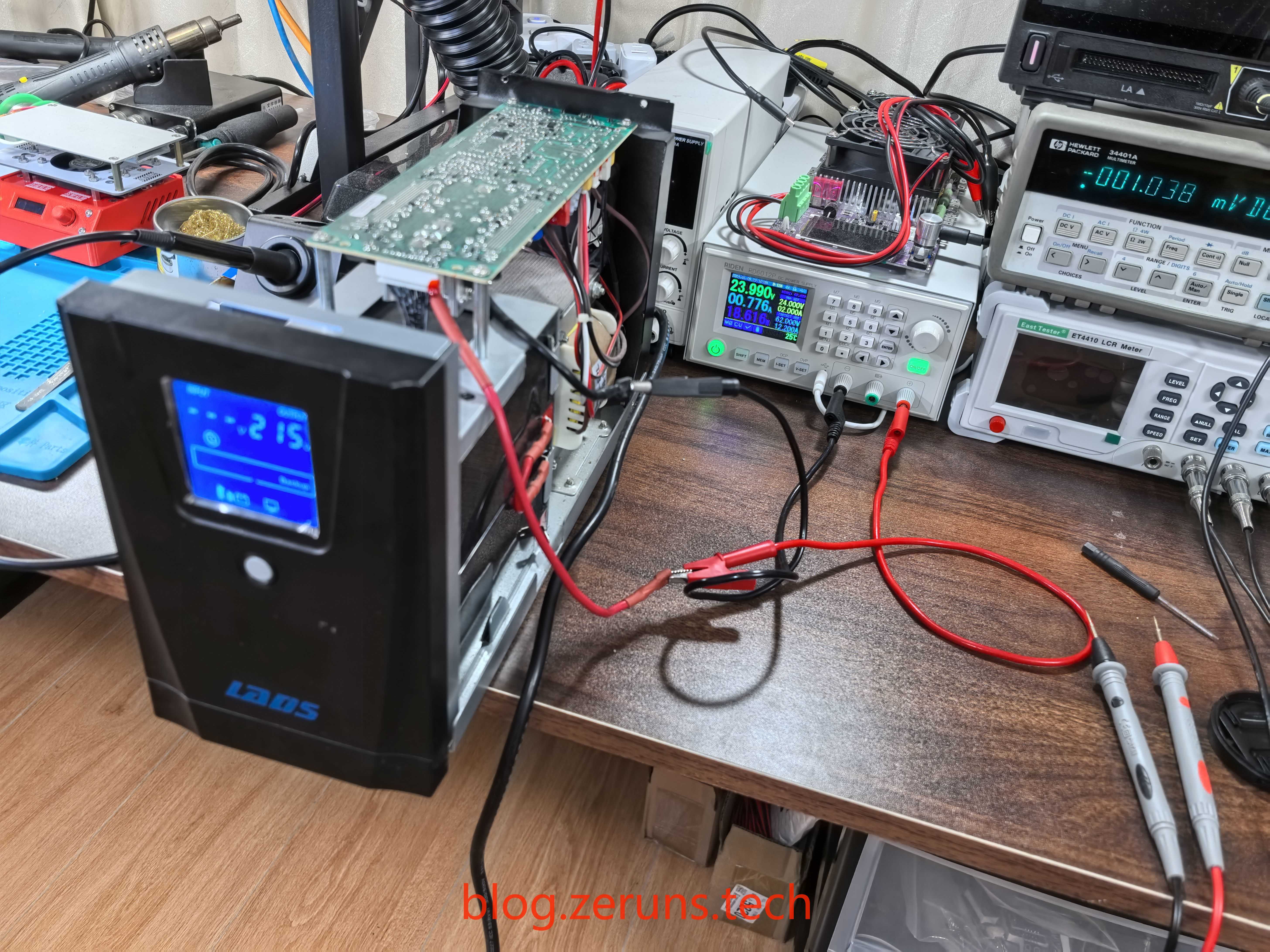
I tested the inverter conversion efficiency: input power 104W, output power 80W, efficiency around 77%.
I attempted to charge the battery separately. It charged to 24V in just a few seconds (two batteries in series), but the charging current was very small. After disconnecting the charger, the battery voltage dropped very quickly.
Recommended Reading
- High Value-for-Money and Affordable VPS/Cloud Server Recommendations: https://blog.zeruns.com/archives/383.html
- Minecraft Server Setup Tutorial: https://blog.zeruns.com/tag/mc/
- Build a Blog Website Without Code! Ultra-Detailed Personal Blog Setup Tutorial: https://blog.zeruns.com/archives/783.html
- Rainyun Ningbo 8272CL High Bandwidth DDoS Protection Cloud Server Performance Review, up to 500Mbps Bandwidth and 1TB Cloud Disk: https://blog.zeruns.com/archives/789.html
- STM32-Based Synchronous Rectification Buck-Boost Digital Power Supply Open Source: https://blog.zeruns.com/archives/791.html