Open-sourcing a 65W PD fast-charging GaN charger based on the DK8607AD power chip, using an Active Clamp Flyback (ACF) topology: IP6538-AC-65W + XPM52CDP65.
Download links for project files are at the end of this article!
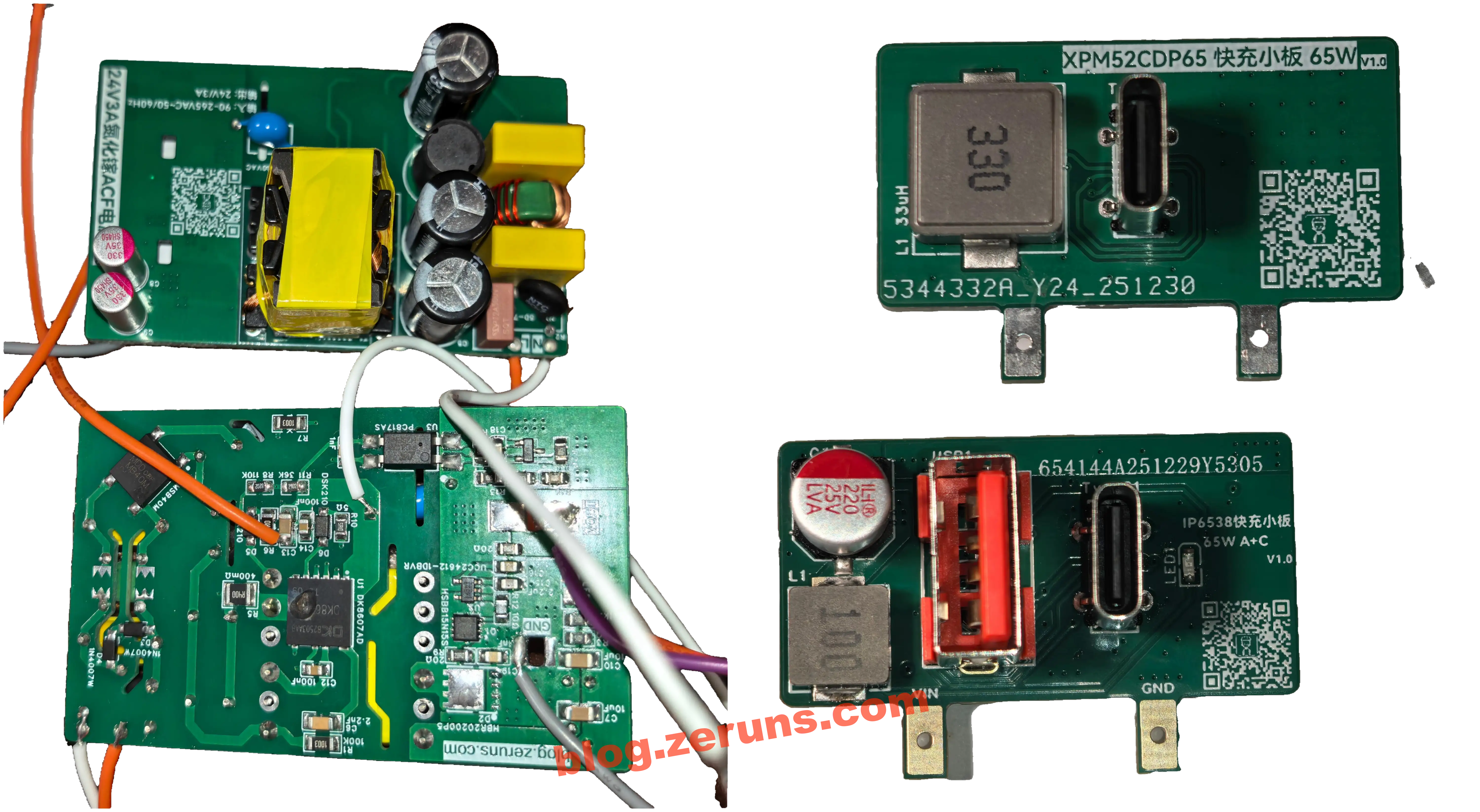
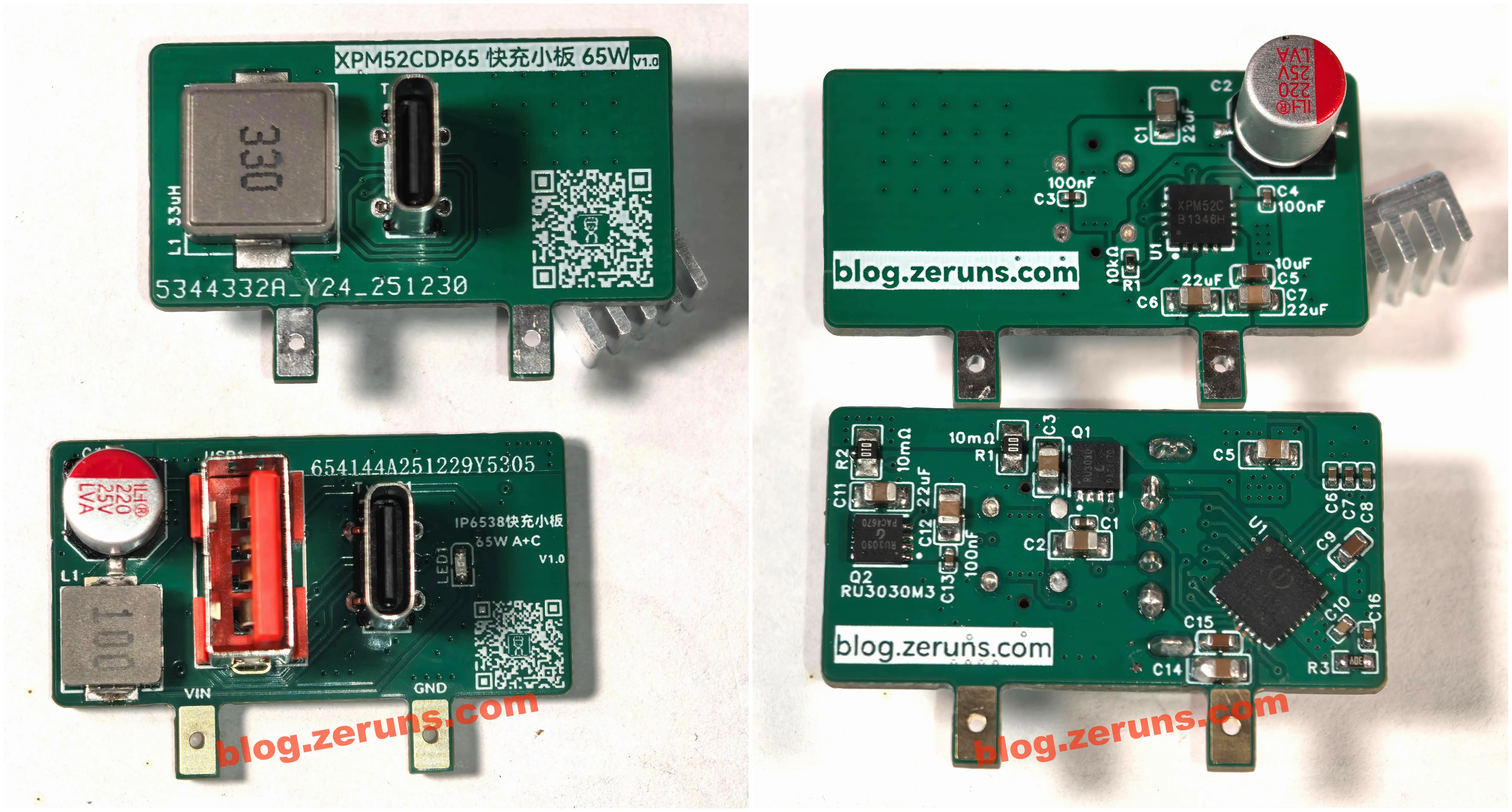
Physical Photos
Front and back of the GaN flyback power base board, and front of the 65W fast-charge DCDC sub-board:
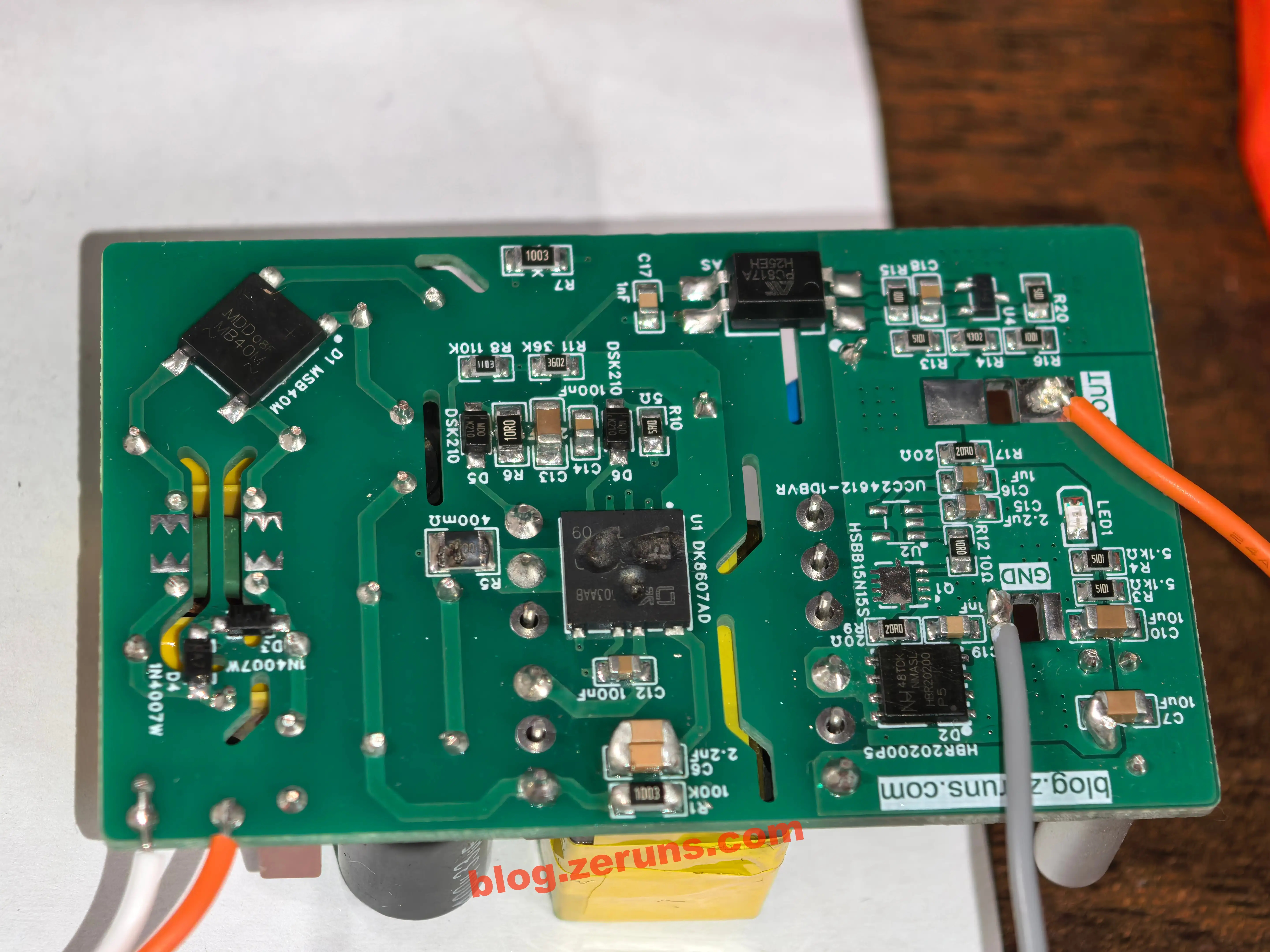
Back of the DCDC fast-charge sub-board:
Project Description
This project consists of a GaN-based active clamp flyback power base board (24V/3A) and a 65W fast-charge DCDC sub-board.
Two different designs were made for the fast-charge sub-board:
- IP6538-AC-65W chip, Buck step-down converter with integrated MOSFETs, dual USB-A + Type-C ports
- XPM52CDP65 chip, Buck step-down converter with integrated MOSFETs, single Type-C port
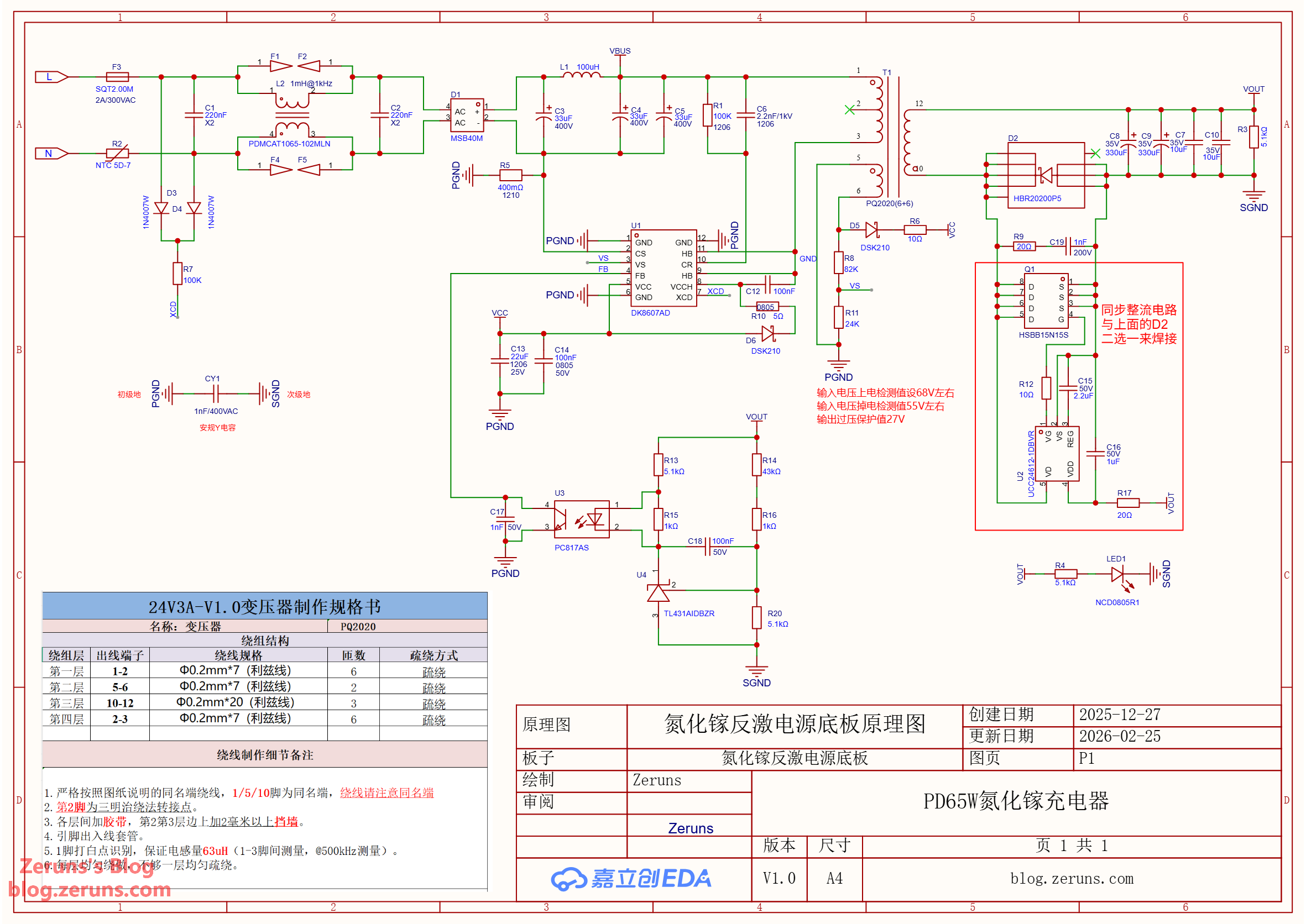
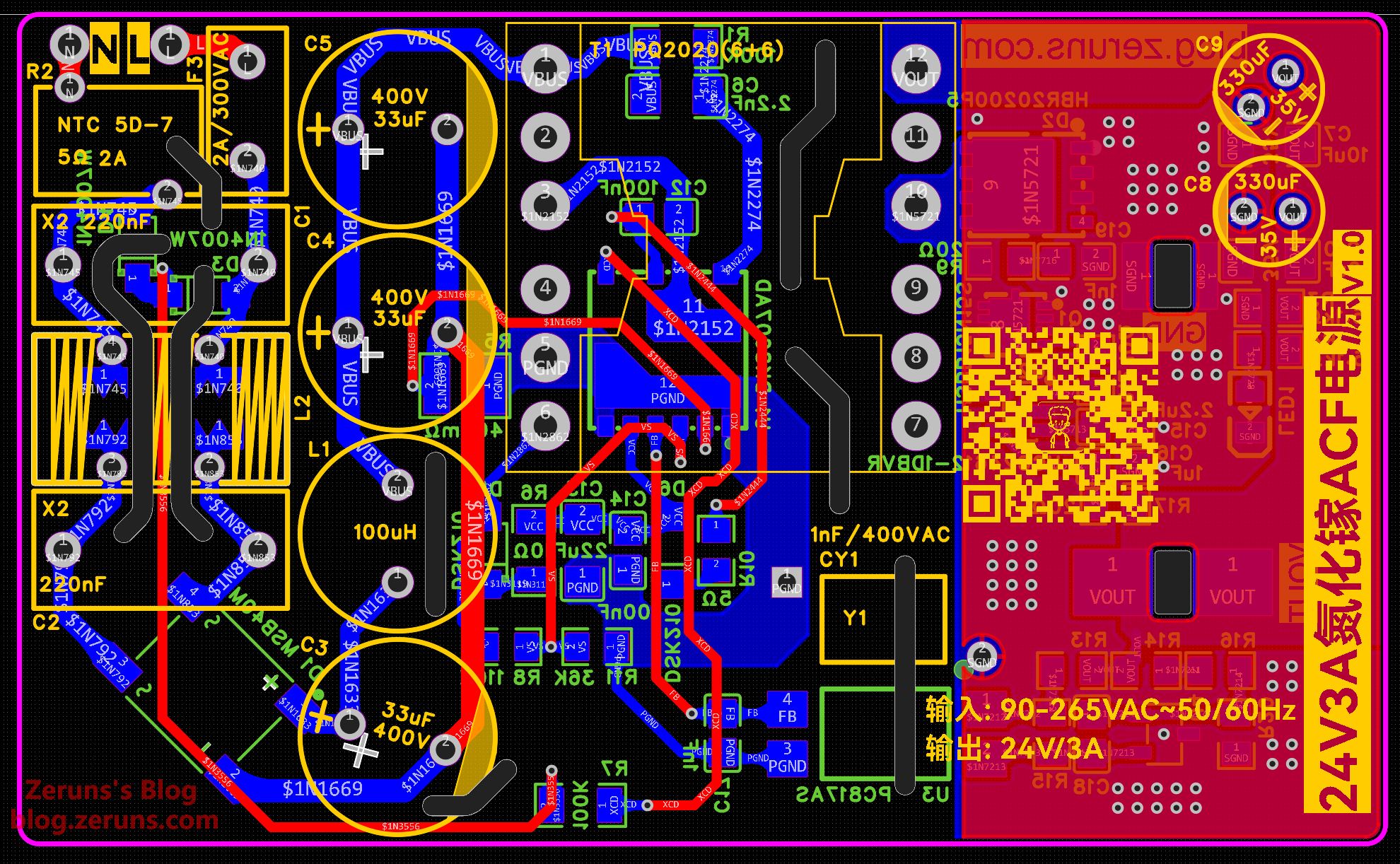
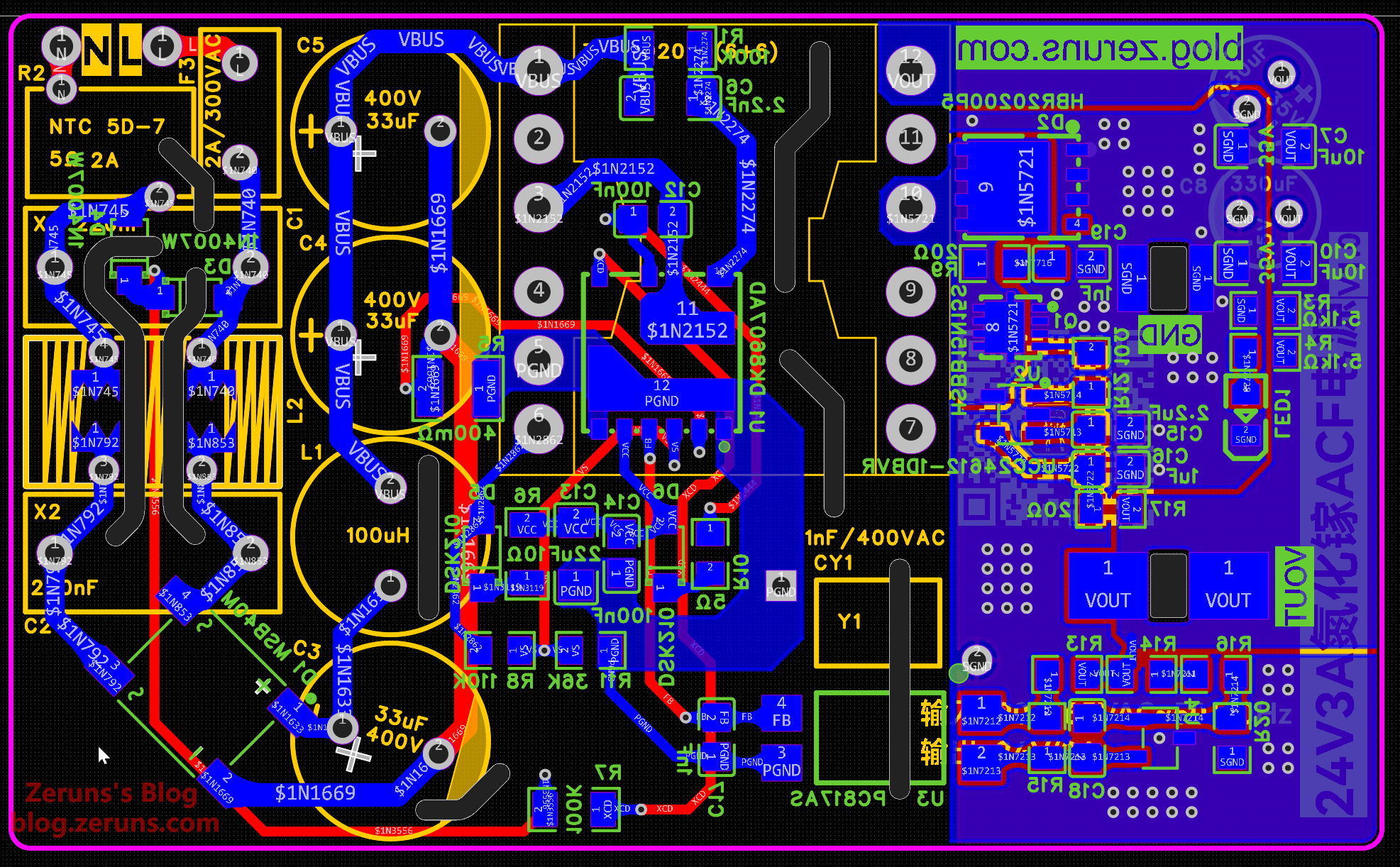
The GaN flyback power base board uses Dongke Semiconductor’s DK8607AD primary-side controller, which integrates two GaN FETs and supports up to 1MHz switching frequency. On the secondary side, rectification can be achieved via either HBR20200P5 Schottky diode or UCC24612 + HSBB15N15S synchronous rectifier — designed as optional components for selective soldering.
This project is actually considered a failure, as the GaN flyback power base board failed to operate properly. However, the 65W fast-charge DCDC sub-board tested perfectly fine. I’m sharing it here to seek advice from experts on what might have gone wrong.
Four prototype boards of the power base were assembled; below are brief descriptions of the issues encountered:
- Board #1: No startup upon powering, no output, auxiliary winding has no voltage, input power ~0.5W
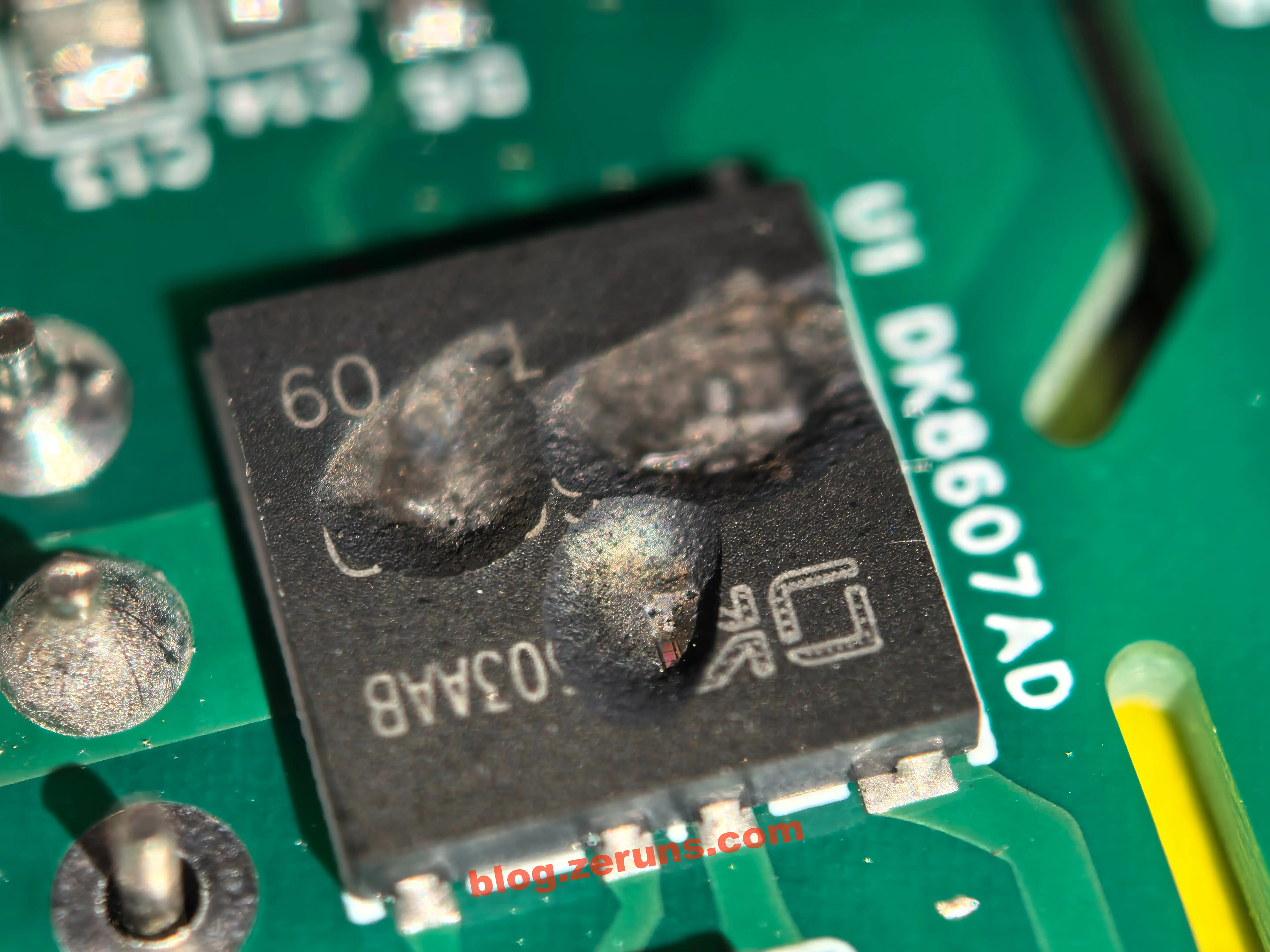
- Board #2: DK8607AD chip exploded immediately after power-on, causing input short circuit
- Board #3: Failed to start, input power ~0.5W, no voltage on auxiliary winding. However, when AC was disconnected, the system briefly started — producing ~15V on the rectified auxiliary winding for tens of microseconds before shutting down, followed by explosion of the DK8607AD chip
- Board #4: Immediate destruction of DK8607AD chip and current sensing resistor upon power-on, resulting in open-circuit condition post-failure
Photos of damaged boards after chip explosions:
Transformer Parameters and Measured Data
Calculated using SMPSKit software. Software download link: https://bbs.eeclub.top/t/smpskit/196
Screenshot of transformer calculation results:
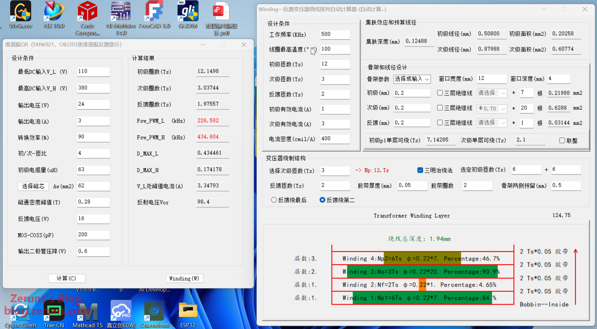
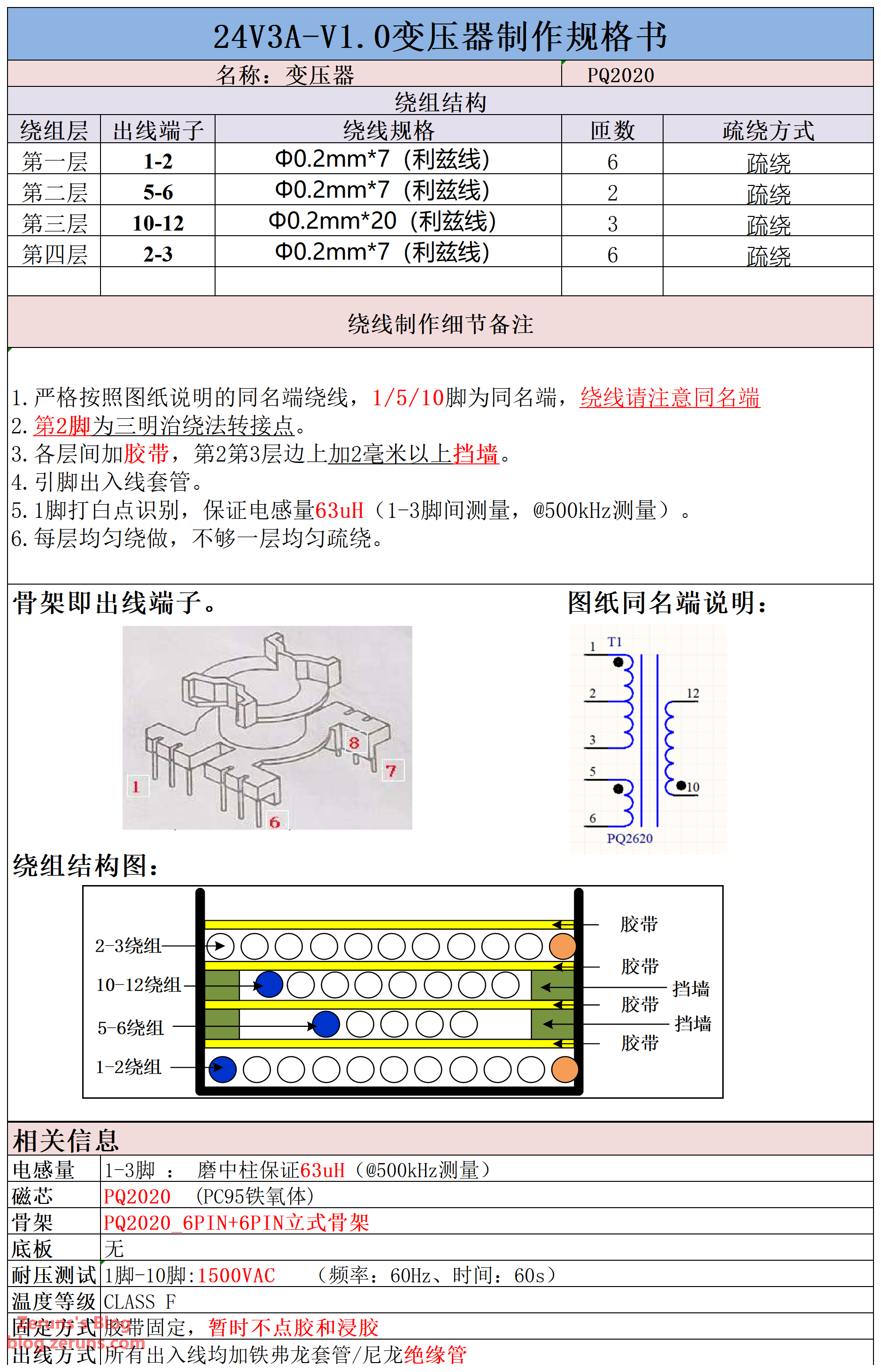
Transformer core: PQ2020, primary inductance target: 63μH. Winding specifications:
| Layer | Terminals | Wire Specification | Turns | Spacing Method |
|---|---|---|---|---|
| 1st | 1-2 | Φ0.2mm×7 (Litz wire) | 6 | Spaced |
| 2nd | 5-6 | Φ0.2mm×7 (Litz wire) | 2 | Spaced |
| 3rd | 10-12 | Φ0.2mm×20 (Litz wire) | 3 | Spaced |
| 4th | 2-3 | Φ0.2mm×7 (Litz wire) | 6 | Spaced |
Transformer specification sheet:
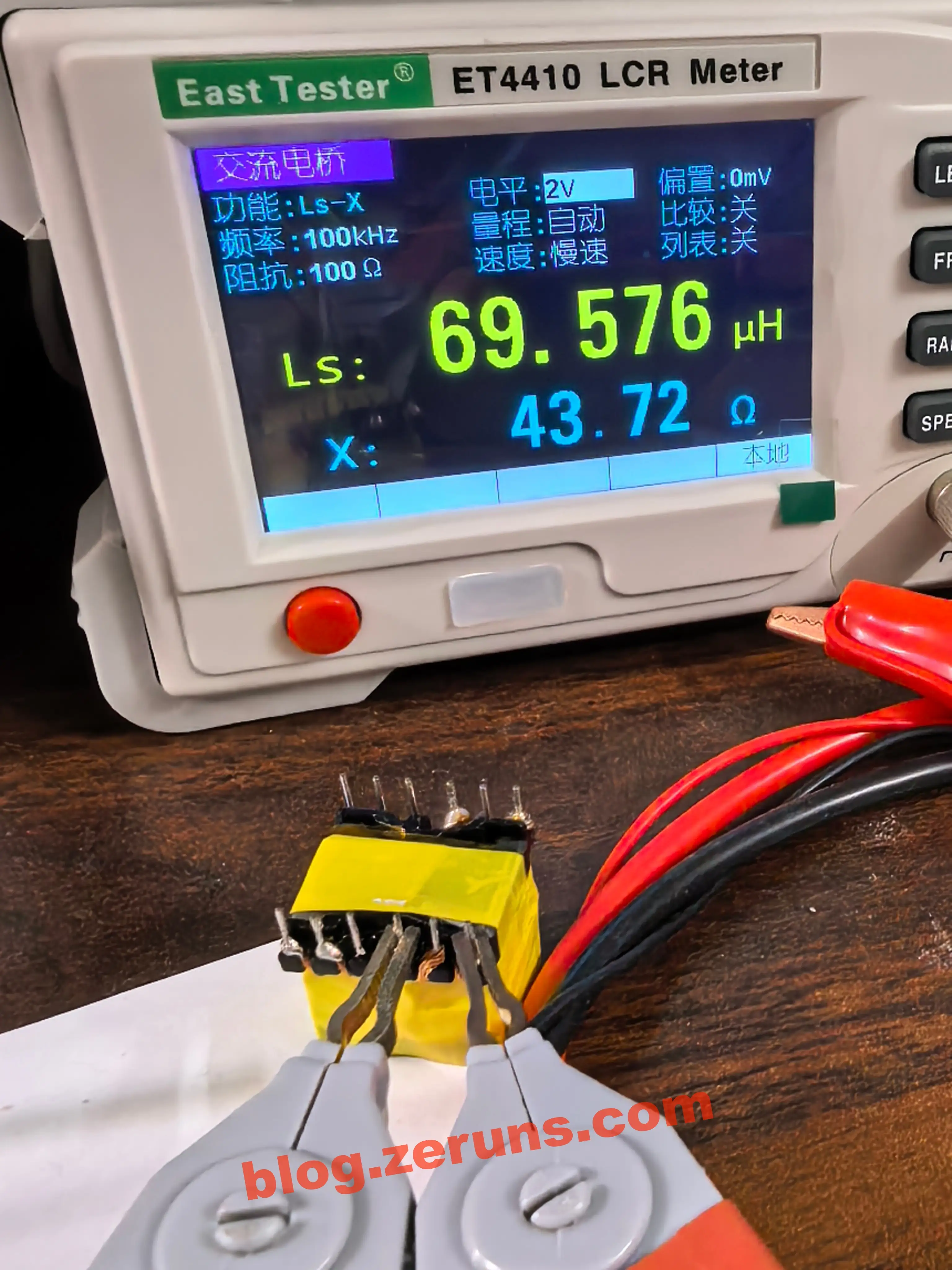
Measured primary inductance after winding: 69.576μH
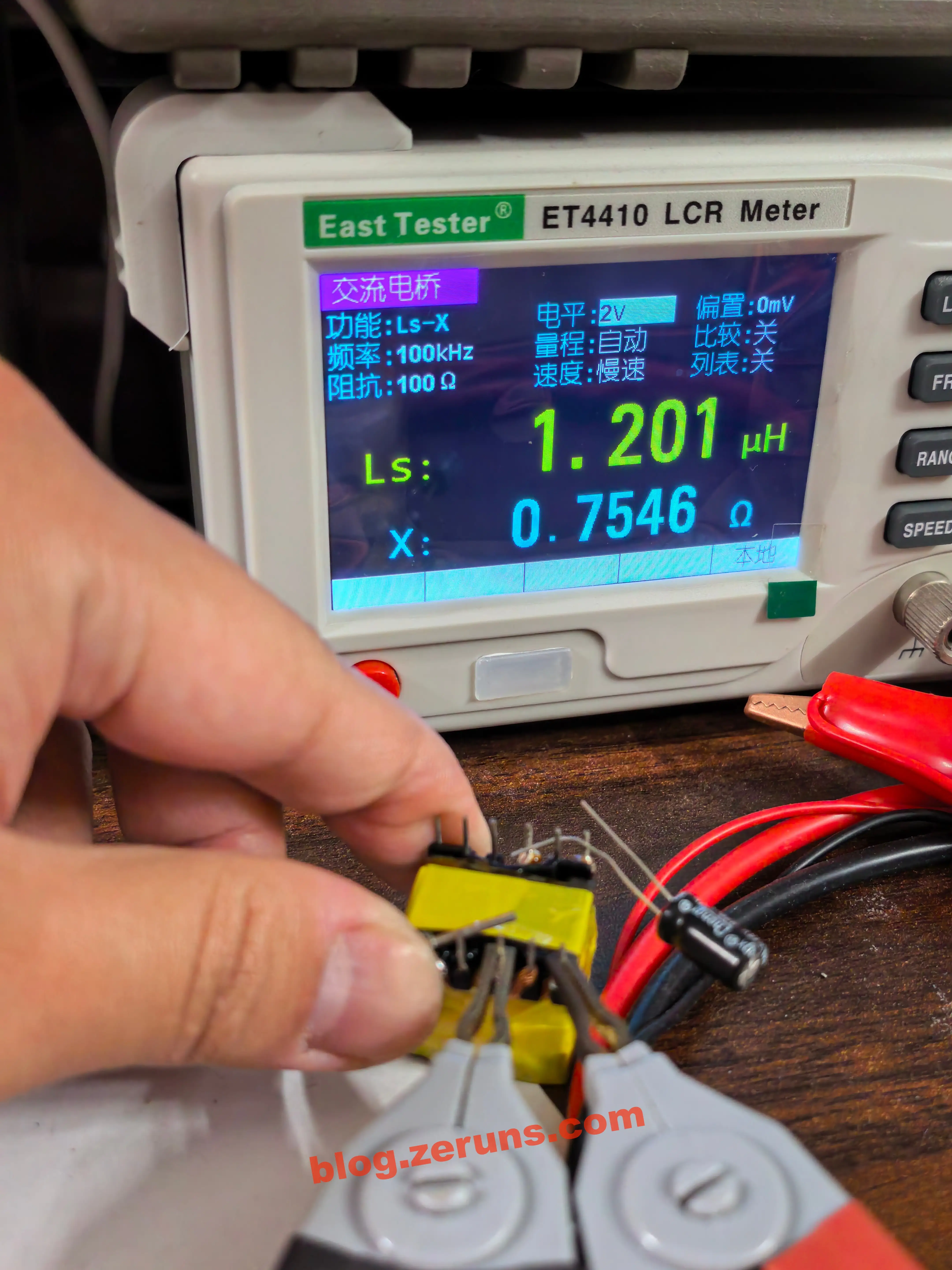
Primary leakage inductance: 1.2μH, slightly high — likely due to imperfect hand-winding.
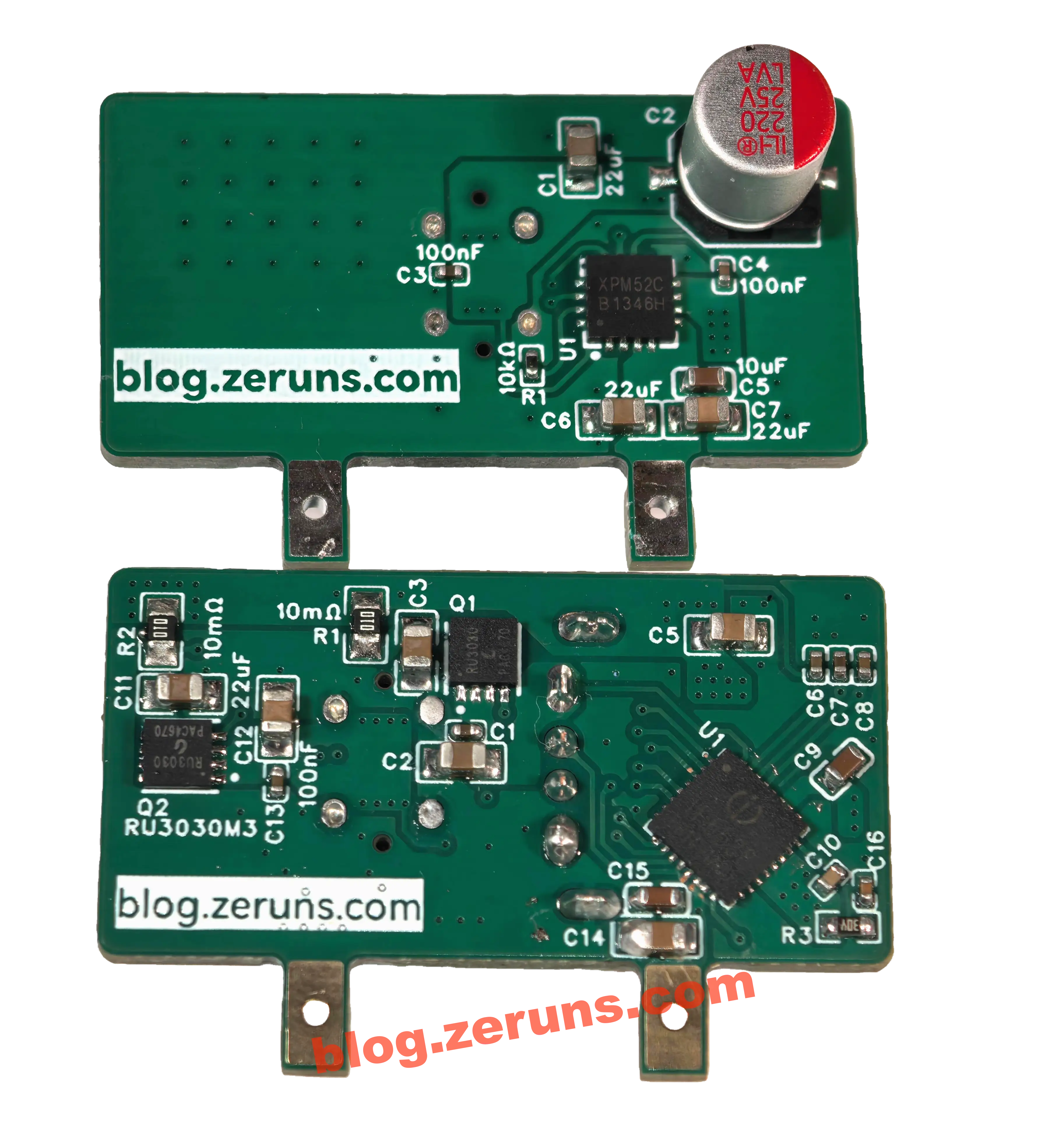
Testing of DCDC Fast-Charge Sub-Board
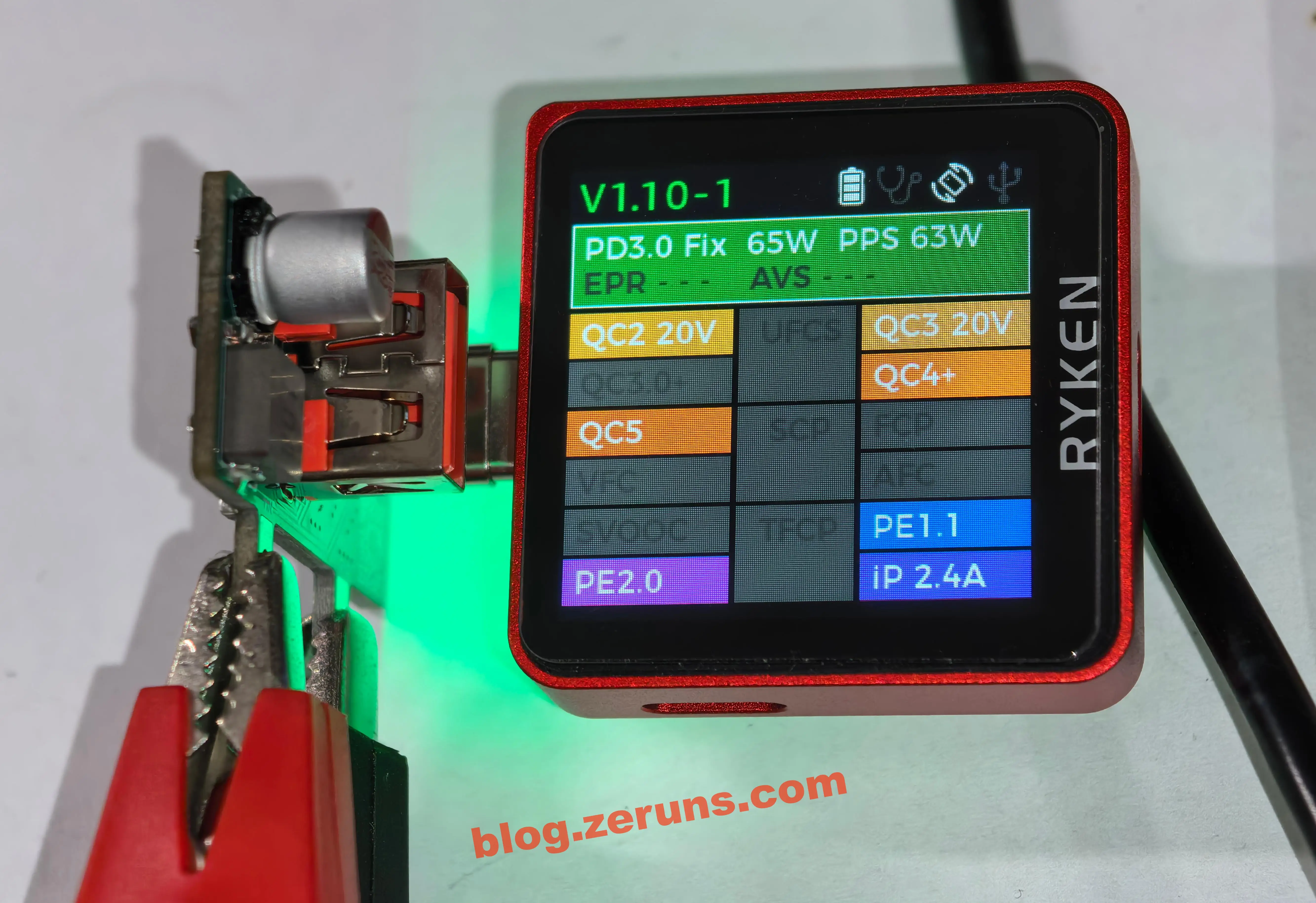
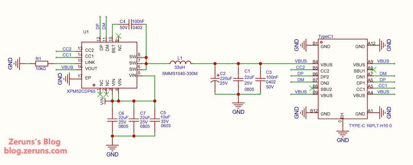
XPM52CDP65
XPM52C is an integrated synchronous buck converter supporting multiple fast-charging protocols including USB Type-C and PD, Qualcomm QC 2.0/3.0/3.0+, Huawei FCP/SCP/HVSCP, VOOC 2.0/4.0, MediaTek PE, Samsung AFC, USB BC1.2 DCP, and Apple 2.4A. It provides a complete solution for car chargers, adapters, smart power strips, etc. The IC automatically detects VIN input voltage and adjusts output accordingly. With built-in power MOSFETs, it supports input voltages up to 31V, output range from 3.3V to 21V, and delivers up to 65W. Output operates in CV (constant voltage) mode when load current is below threshold, switches to CC (constant current) mode above threshold. Features line-drop compensation to maintain stable output under heavy loads. Integrates proprietary XPD-LINK communication technology for flexible multi-port Type-C applications. Supports reprogramming and online firmware updates. Includes protections: input OVP/UVP, output OCP/short-circuit, and thermal shutdown. Package: QFN4x4-16L.
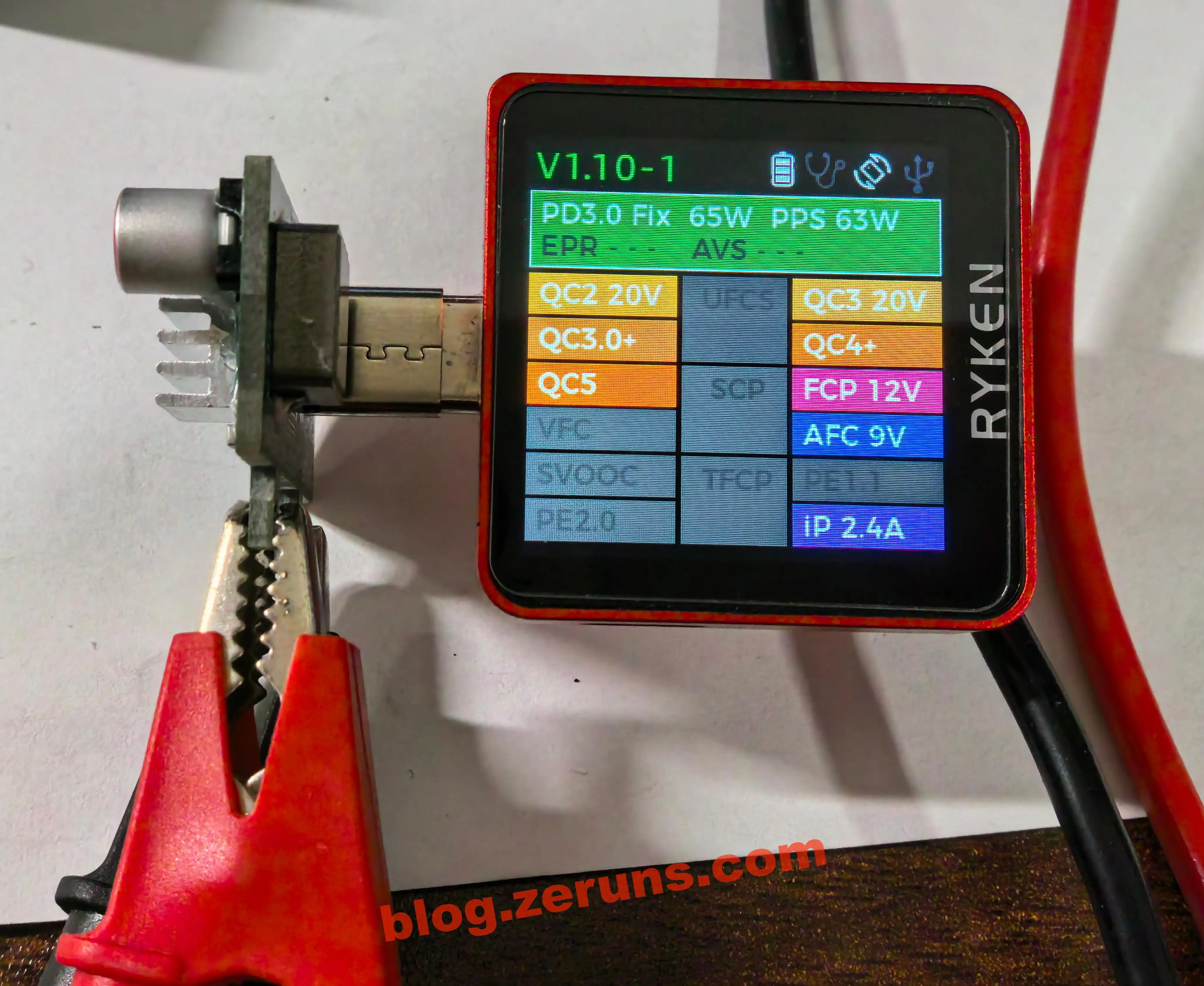
Fast-charging protocol test results:
Successfully supports: PD3.0 FIX 65W, PPS 63W, QC2 20V, QC3 20V, QC3.0+, QC4+, QC5, FCP 12V, AFC 9V, Apple 2.4A.
USB power meter used: Ruiken X3 — https://s.click.taobao.com/575iCMn
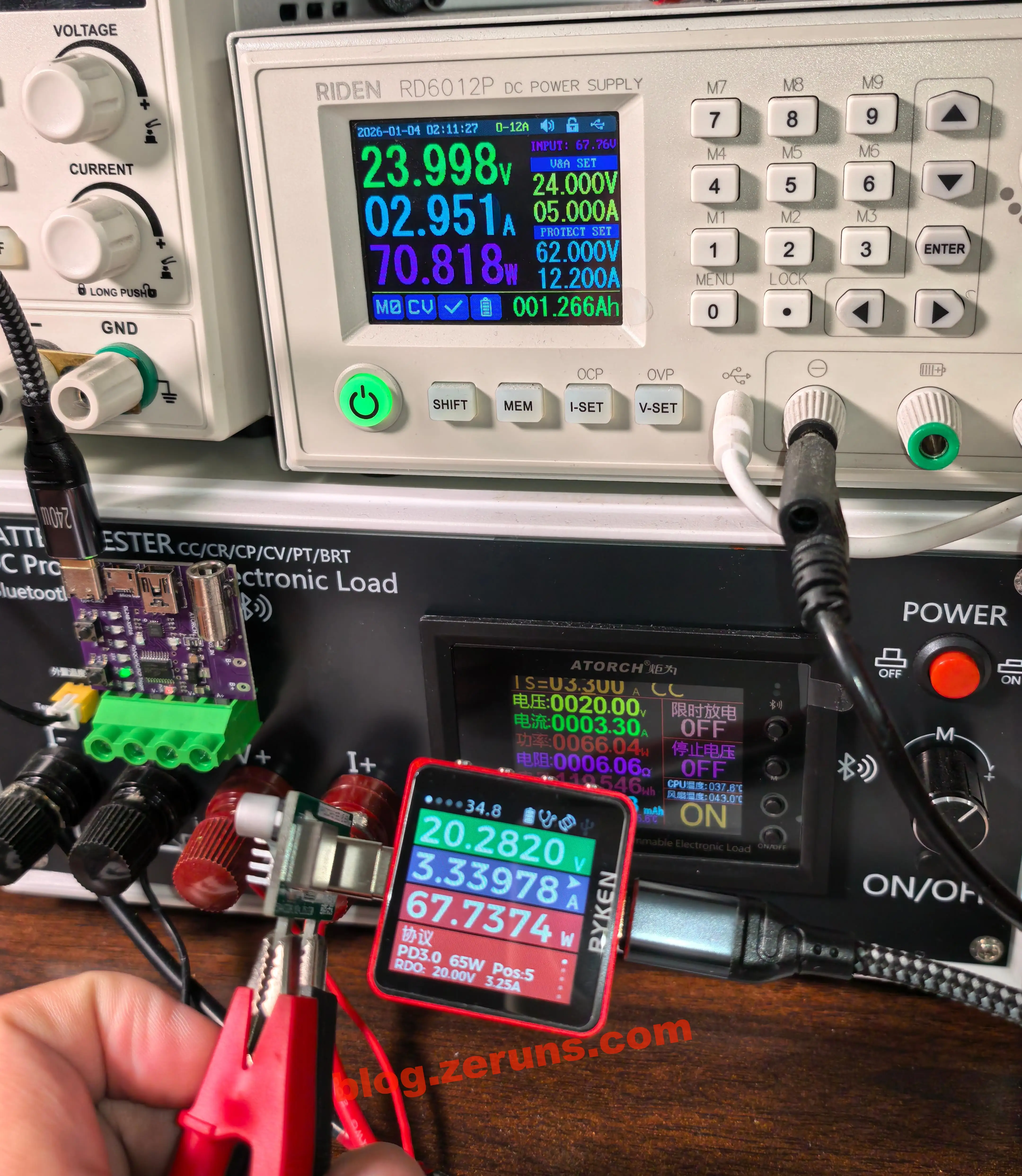
Load testing: Input voltage 24V, PD negotiation to 20V, electronic load set to 3.3A.
Measured output power: 67.74W, input power: 70.8W, efficiency: 95.65% — excellent performance.
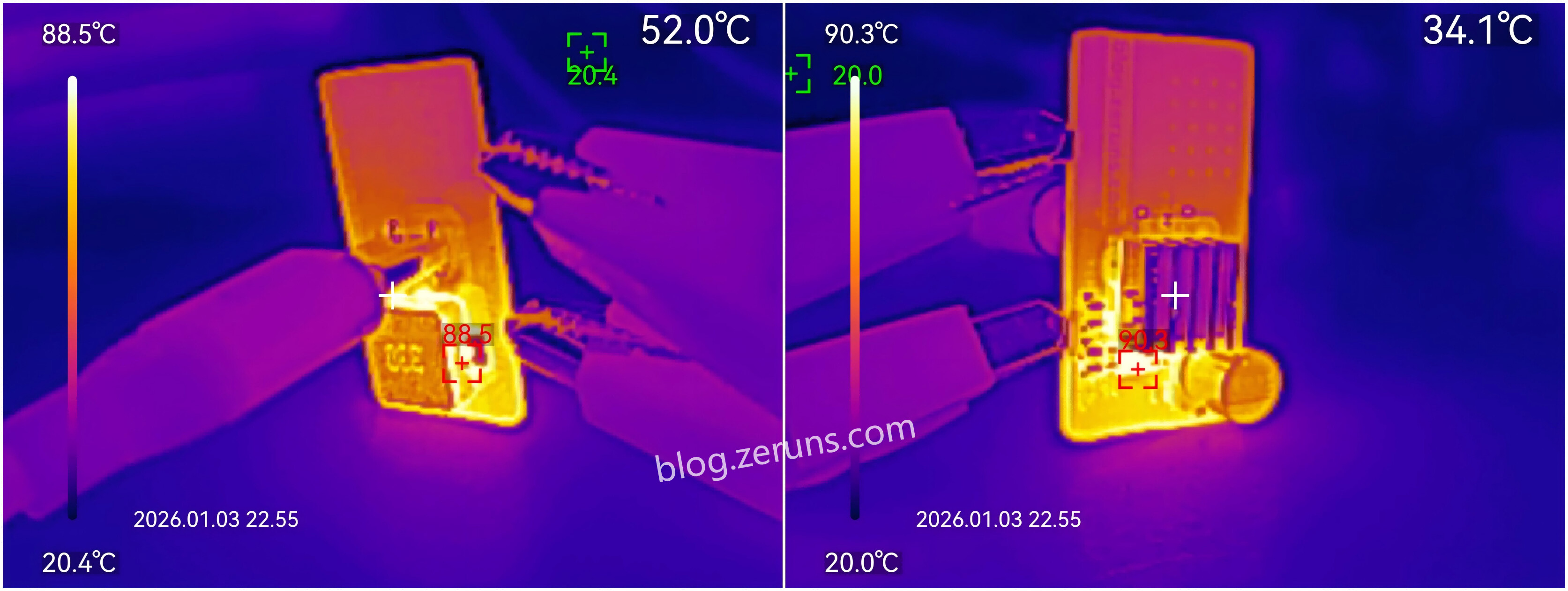
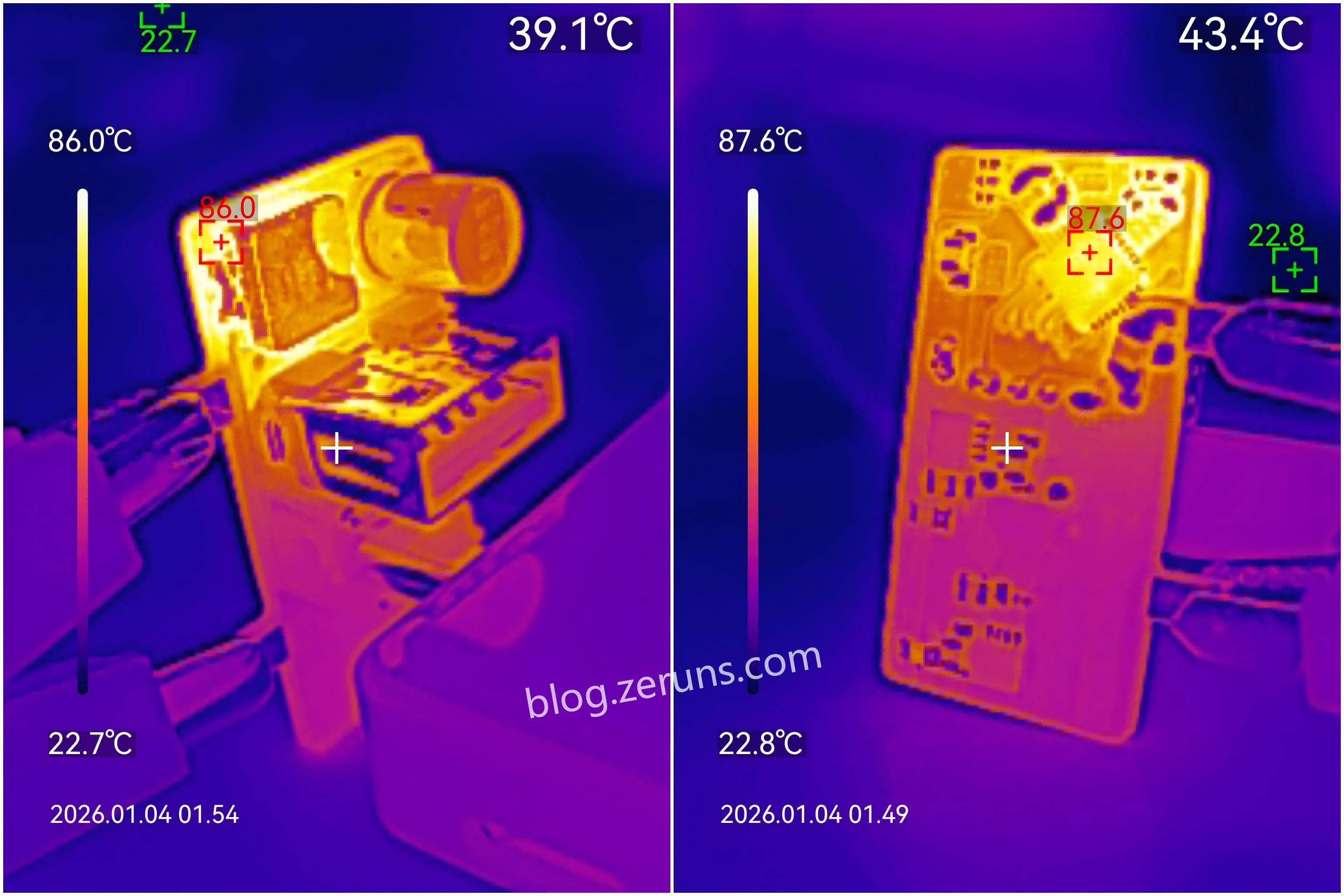
Thermal imaging at maximum load: Maximum chip temperature ~90.3°C (with small heatsink attached).
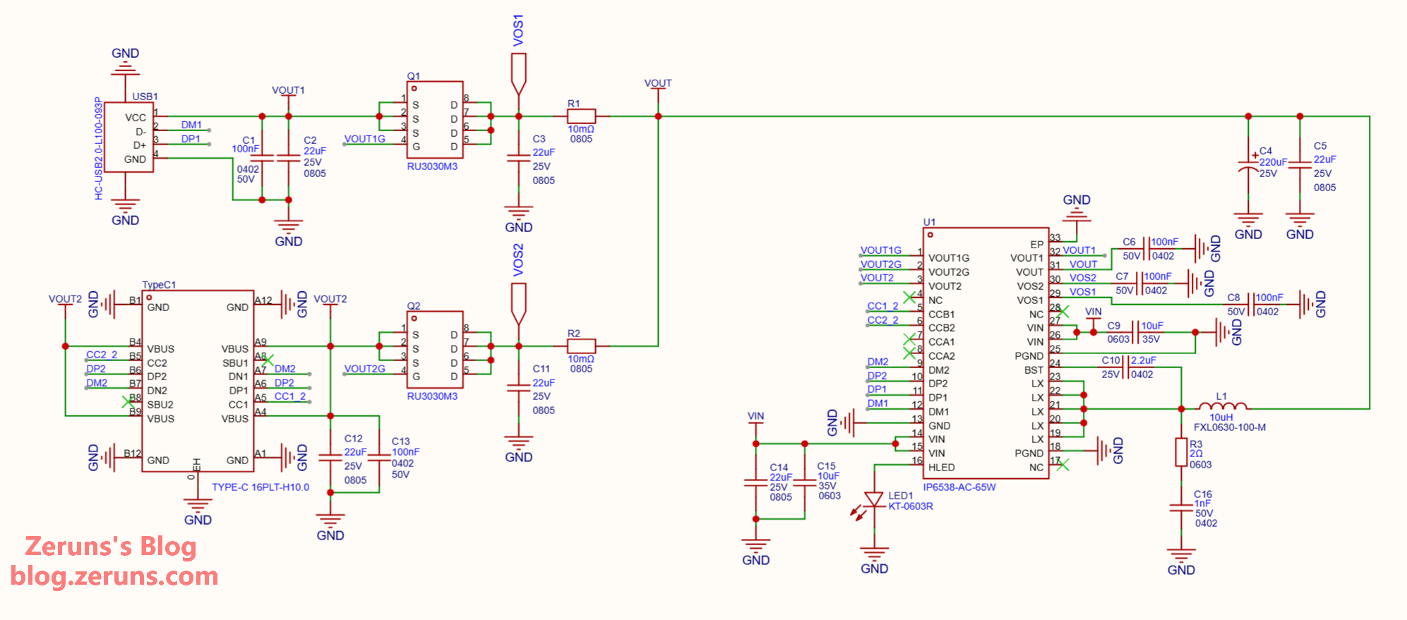
IP6538
IP6538 is a dual-port SOC IC integrating a synchronous buck converter, supporting 14 fast-charging protocols including USB PD2.0/PD3.0(PPS), suitable for car chargers, fast chargers, and smart power strips. Supports dual USB-C, USB-C + USB-A, or dual USB-A configurations. Features automatic plug detection — either port alone supports fast charging; when both are used simultaneously, both output 5V with total current up to 4.8A. Built-in MOSFETs, input voltage range: 8.2V–32V, output range: 3V–20V.
Fast-charging protocol test results:
Successfully supports: PD3.0 FIX 65W, PPS 63W, QC2 20V, QC3 20V, QC4+, QC5, PE1.1, PE2.0, Apple 2.4A.
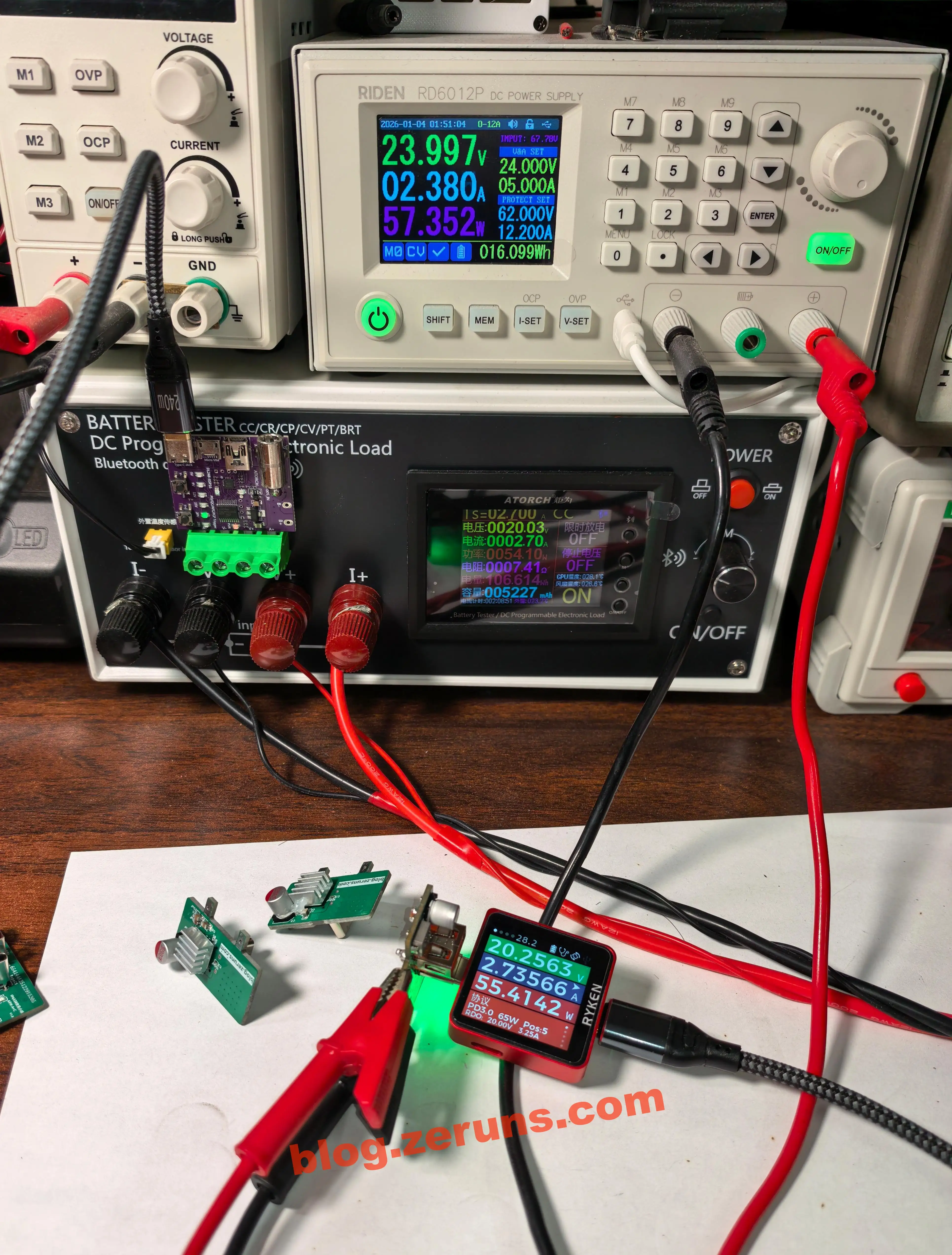
Load testing: Input voltage 24V, PD negotiation to 20V, electronic load set to 2.7A.
Measured output power: 55.41W, input power: 57.35W, efficiency: 96.62%.
Not sure if it’s due to my design or a batch issue with these chips — they trigger protection when current exceeds 2.7A. Another project using the same schematic does not exhibit this problem. See related open-source 140W+65W buck-boost PD3.1 fast-charge module (2C+1A): https://blog.zeruns.com/archives/801.html
Thermal imaging at maximum supported load: Chip temperature ~87.6°C, no heatsink.
Schematics
GaN Flyback Power Base Board
XPM52CDP65 Fast-Charge Sub-Board
IP6538 Fast-Charge Sub-Board
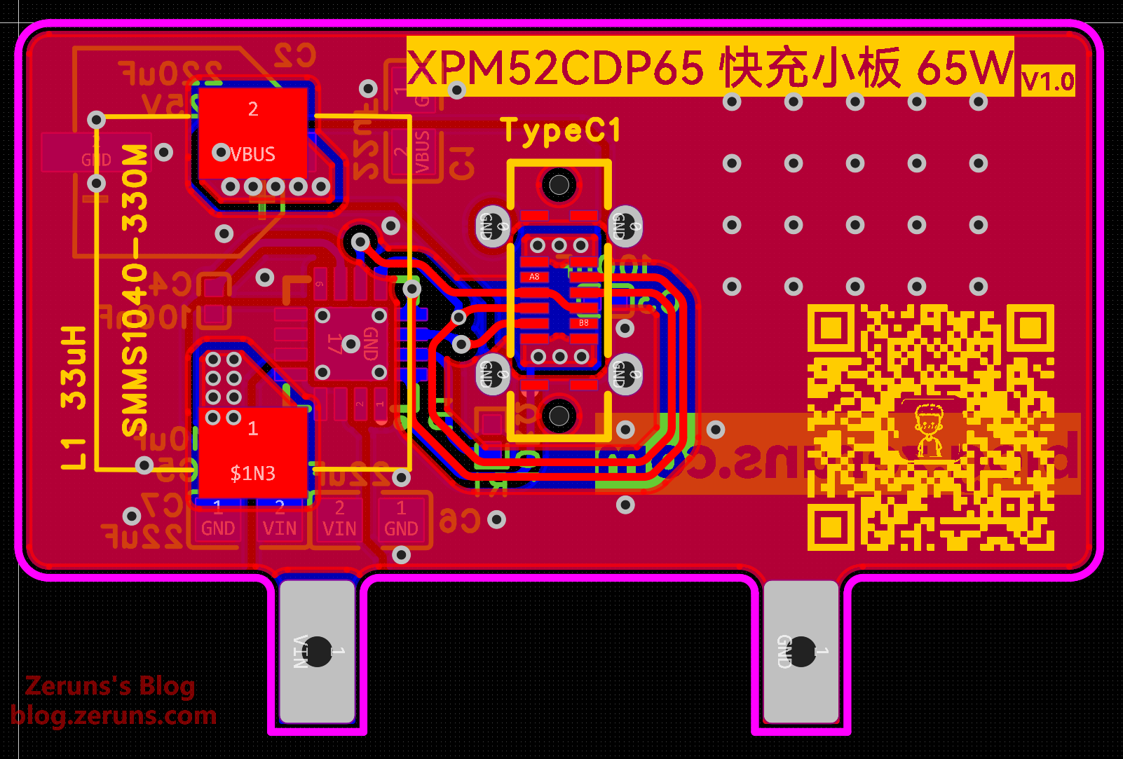
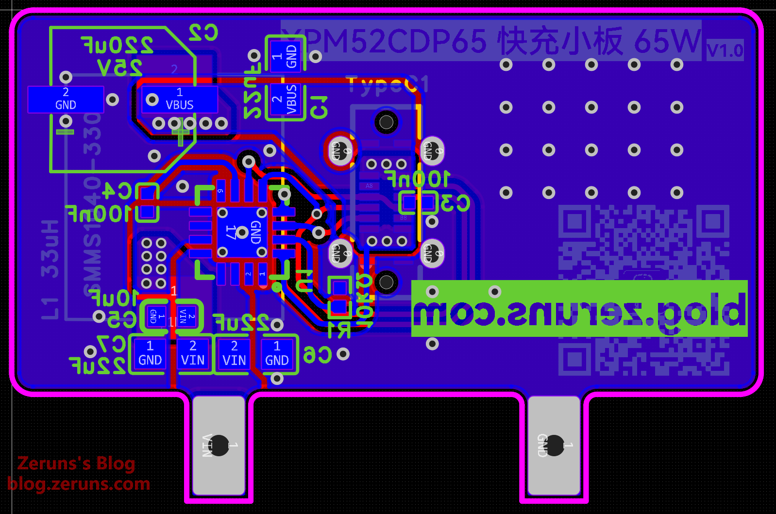
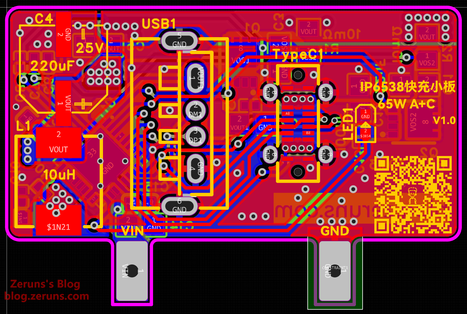
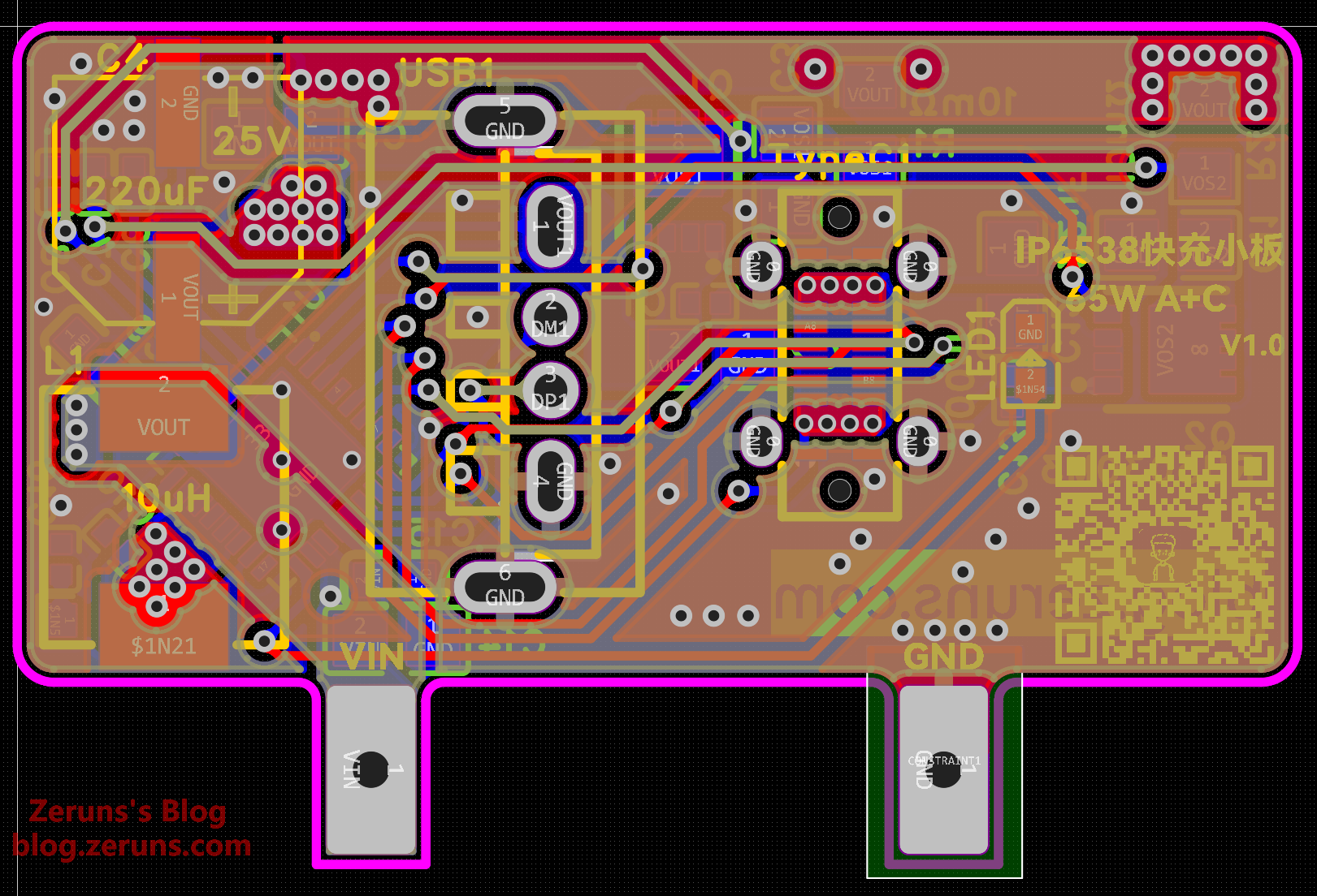
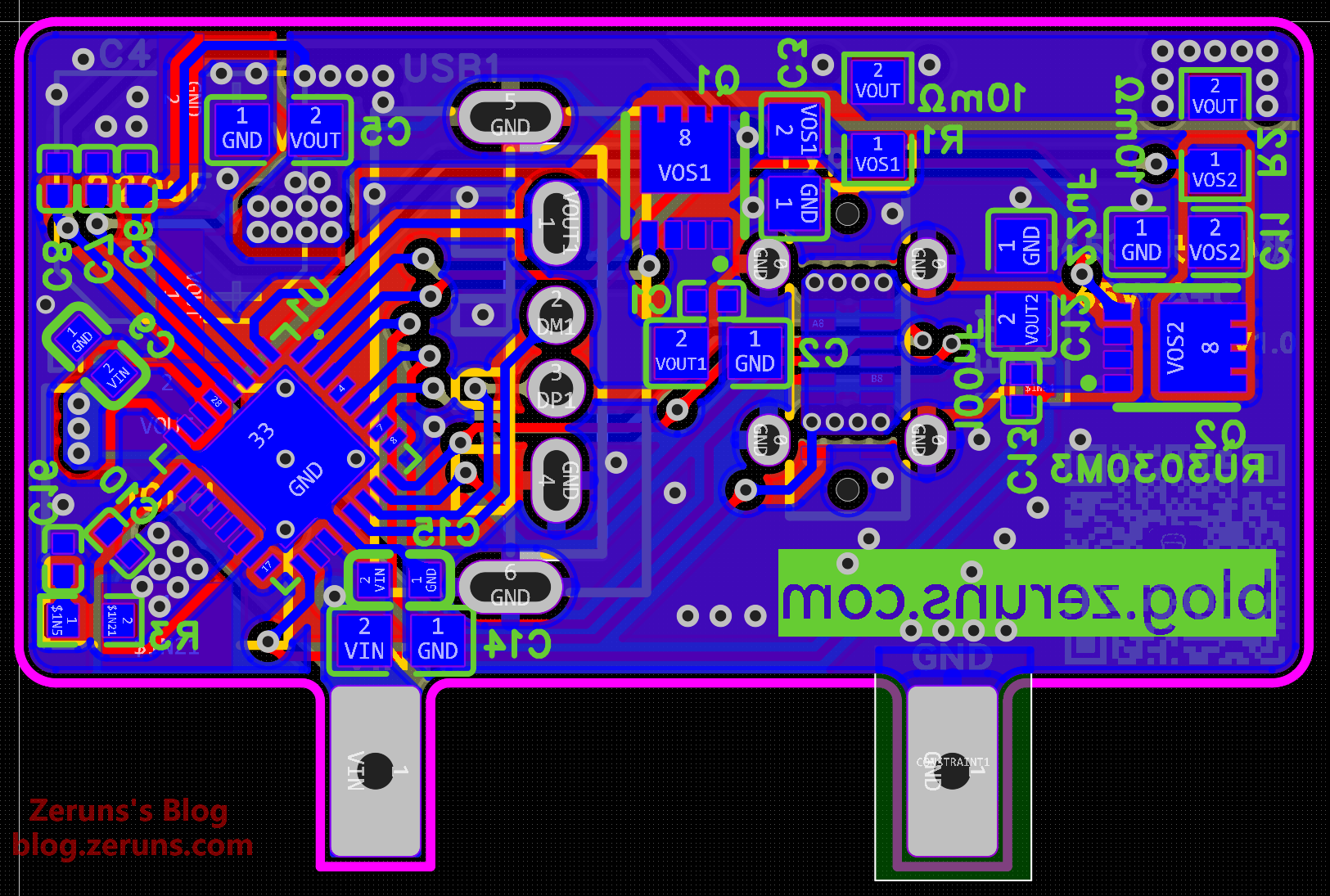
PCB Layouts
GaN Flyback Power Base Board
XPM52CDP65 Fast-Charge Sub-Board
IP6538 Fast-Charge Sub-Board
Component Purchase Links
Purchase links for some components used in this project are listed below:- 0402/0603 Resistor and Capacitor Sample Book: https://s.click.taobao.com/3rAjyQn
- SMT Stencil: https://s.click.taobao.com/EMrr8Gn
- PQ2020 Core and Bobbin: https://s.click.taobao.com/DLPE8Gn
- MSB40M: https://s.click.taobao.com/ToQ68Gn
- NTC 5D-7: https://s.click.taobao.com/LrD08Gn
- XPM52CDP65: https://s.click.taobao.com/8r3VxQn
- Litz Wire: https://s.click.taobao.com/IuyT7Gn
- Surface-Mount Solid-State Capacitors: https://s.click.taobao.com/xylswQn
It is recommended to purchase components from LCSC (EasyEDA): https://activity.szlcsc.com/invite/D03E5B9CEAAE70A4.html
You can click “Order Now on LCSC” in the BOM table of the Open Source link on LCSC to import all required components into your shopping cart with one click.
Download Resources
Resources include: EasyEDA project files, schematic PDFs, SMPSKit software, datasheets for used chips, interactive BOM (for soldering assistance), transformer specifications, Gerber files, and stencil file for three boards panelized together (within 10*10 cm, stencil service on Taobao, ~15 RMB).
- 123Yunpan download link: https://www.123865.com/s/2Y9Djv-MaddH
- Baidu Wangpan download link: https://pan.baidu.com/s/1yrOYifFEItxbd1aHXmoq4A?pwd=6k1n Password: 6k1n
- Open-source link on LCSC OSH Hub: https://oshwhub.com/zeruns/pd65w-gallium-nitride-charger
![]() QQ Group for Electronics/MCU Technical Discussion: 2169025065
QQ Group for Electronics/MCU Technical Discussion: 2169025065
![]() eeClub - Electronic Engineers Community: https://bbs.eeclub.top/
eeClub - Electronic Engineers Community: https://bbs.eeclub.top/
Recommended Open-Source Projects- Open-source three-phase power meter, convenient for monitoring home electricity usage: https://blog.zeruns.com/archives/771.html
- Open-source synchronous rectification Buck-Boost digital power supply based on STM32: https://blog.zeruns.com/archives/791.html
- LM25118 automatic buck-boost adjustable DCDC power module: https://blog.zeruns.com/archives/727.html
- Open-source intelligent electronic load based on CH32V307, competition project from an embedded systems contest: https://blog.zeruns.com/archives/785.html
- EG1151 high-power synchronous rectification adjustable buck-boost power module (supports Type-C PD fast charging input), open-source: https://blog.zeruns.com/archives/794.html
- Open-source 140W+65W buck-boost PD3.1 fast charging module (2C+1A ports), IP6557+IP6538, 205W desktop charger: https://blog.zeruns.com/archives/801.html
- Open-source Type-C docking station with four 10Gbps USB-A ports + 2.5G Ethernet card + card reader: https://blog.zeruns.com/archives/868.html
- [Open-source] 24V 3A flyback switching power supply based on UC3842 (including circuit and transformer parameter calculation): https://blog.zeruns.com/archives/910.html
- [Open-source] Adjustable buck-boost DCDC power supply based on SC8703, voltage and current adjustable, supports PD fast charge input: https://blog.zeruns.com/archives/929.html
Recommended Reading
- Recommended affordable and cost-effective VPS/cloud servers: https://blog.zeruns.com/archives/383.html
- Minecraft server setup tutorial: https://blog.zeruns.com/tag/mc/
- GL-RM1PE simple unboxing review and teardown – enabling BMC remote management on regular PCs: https://blog.zeruns.com/archives/900.html
- Discourse forum setup guide – deploying an open-source Discourse community forum website from scratch: https://blog.zeruns.com/archives/919.html
- OWON HDS160 oscilloscope multimeter – simple unboxing review and teardown: https://blog.zeruns.com/archives/927.html
- Quick one-click Minecraft server setup tutorial, supporting all MC versions (Forge, Fabric, Paper, Bedrock, etc.): https://blog.zeruns.com/archives/923.html
English Version of the Article: https://blog.zeruns.top/archives/85.html