Hey experts, anyone familiar with the CC2500 RF chip? How should I configure it to achieve longer transmission distance?
Hey experts, anyone familiar with the CC2500 RF chip? How should I configure it to achieve longer transmission distance?
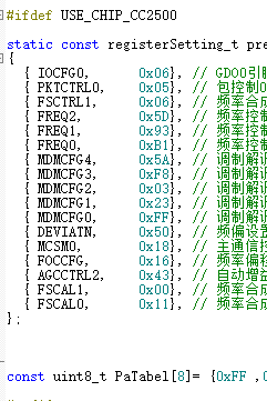
先直接说结论:要提升CC2500的传输距离,核心是最大化发射功率+降低数据速率+优化调制/带宽参数,结合你贴的配置,先修正几个关键寄存器~
你的PaTable[0] = 0xFF是错的!CC2500的发射功率由PATABLE寄存器配置,原生最大输出功率是 +1dBm,对应PATABLE值是0x3E(不同手册可能有细微差异,但0xFF是无效值)。
修改:const uint8_t PaTable[8] = {0x3E, 0xFF, ...}(只需要配置第0项,其他可以留空)。
CC2500的接收灵敏度和数据速率强相关:
数据速率由MDMCFG4+MDMCFG3决定,公式是:
建议配置成2.4kbaud(对应寄存器值:MDMCFG4=0x87,MDMCFG3=0x83),替换你现在的0x58/0x23。
OOK抗干扰极弱,优先用GFSK调制(CC2500的默认推荐),通过MDMCFG2寄存器配置:
MDMCFG2 = 0x02(MOD_FORMAT位设为GFSK),替换你现在的0x23。信道带宽越窄,接收灵敏度越高(但抗多径能力会弱一点,户外场景优先窄带宽):
通过MDMCFG3的CHANBW位配置,建议选203kHz带宽(对应MDMCFG3=0x83),和上面2.4kbaud的配置匹配。
弱信号下,更长的同步字更容易被接收端锁定,通过PKTCTRL0的SYNC_MODE配置:
PKTCTRL0 = 0x08(同步字长度设为4字节),替换你现在的0x06。你贴的PaTable是0xFF,这会导致发射功率异常(甚至可能没输出),先改成0x3E(芯片原生最大+1dBm),如果需要更远可以外挂PA(比如加PA后能到22dBm,但属于硬件扩展了)。
Yo! I see you’re wrestling with the CC2500. That chip is an absolute classic, but getting decent range out of it can definitely be tricky compared to newer LoRa stuff.
I’ve done a ton of designs with this bad boy. Looking at your code snippet (specifically the MDMCFG regs), here is the “secret sauce” to boosting your range.
In the RF world, Data Rate is the enemy of Range.
MDMCFG4 is 0x5A and MDMCFG3 is 0xF8. This sets the data rate.MDMCFG4.You can write the best code in the world, but if your RF path is trash, you won’t go far.
I see const uint8_t PaTabel[8] = {0xFF ... at the bottom.
0xFF is typically the setting for max output power (+1 dBm) on the CC2500. Keep that.TL;DR Checklist for you:
CC2500 想把距离拉远,别只盯着寄存器,先把“链路预算”这条线想明白:发射功率+天线增益-路径损耗-接收灵敏度=余量。余量越大,距离越远。下面从软、硬两块给你一份“踩坑清单”,照着撸一遍,基本能再薅出 30%~50% 的通信距离。
一、软件寄存器层面(你贴的那堆配置)
先把功率拉到芯片能给的极限
你表里 PA_TABLE 只写了一个 0xFF,这是“粗暴满功率”没错,但 CC2500 的 0xFF 对应的是 +1 dBm,离它真正能出的 +12 dBm 还差得远。
正确姿势:
const uint8_t paTable[8] = {0xFE,0xFC,0xF9,0xF6,0xF3,0xE8,0xD8,0xC0};速率能砍就砍
你现在的 MDMCFG 把数据率设到 250 kBaud 以上,灵敏度只有 ‑90 dBm 出头。
把 DRATE_E / DRATE_M 往下压,让空中速率 ≤ 1.2 kBaud,灵敏度能到 ‑110 dBm,直接白捡 20 dB 余量,理论距离再 ×10。
代价:延迟大、吞吐量小,遥控、抄表类场景无所谓。
频道带宽收窄
AGCCTRL2 里若 BW 设 812 kHz,底噪被放进来一大坨。
把 MDMCFG4.CHANBW_E 往高调,让 RX BW ≈ 2×数据速率即可,1.2 kBaud 时 50 kHz 足够,底噪降 10log(812/50)≈12 dB,又白捡一倍距离。
前向纠错 & 白化
PKTCTRL0 打开 FEC(bit5=1),CC2500 内部有 1/2 卷积码,灵敏度再下 2–3 dB;再把数据白化打开,防止长 0/1 导致 DC wander,实际场测能少 1–2 dB 衰落。
频率别跑 2.4 G,回 433 / 868
2.4 GHz 自由空间损耗比 433 MHz 高 16 dB,穿墙再差 10 dB。只要法规允许,果断切 433 MHz(中国 470 M 也行),同一套参数距离直接翻倍。
二、硬件层面(很多软件工程师容易忽略)
天线端“三件套”
电源干净才能远
PA 瞬间 60 mA 爬升,如果走线长 5 cm、宽 0.2 mm,瞬压跌落 200 mV,功率掉 2 dB。
接收端 LNA
如果主控板空间够,在 CC2500 前级串一颗 MAX2640,NF 0.9 dB,增益 15 dB,系统灵敏度直接下 12 dB,发射端功率不变,距离又能翻两番。注意 LNA 输入端加 0900BL15B050 型隔离器,防止 TX 大功率倒灌烧毁。
地平面 & 屏蔽罩
433 MHz 波长 69 cm,板子地平面小于 λ/4 时辐射效率雪崩。
高度 & 极化
实测 433 MHz 在 1 m 高度通信距离 300 m,把一端抬高到 3 m,菲涅耳区 clearance 够,距离直接 800 m。两端天线都竖直极化,交叉极化损耗能少 20 dB。
三、快速验证流程
一句话:先把速率砍慢、功率拉满、带宽压窄,再把天线/匹配/电源/屏蔽这些“硬骨头”啃了,CC2500 也能飞 1 km+,别只蹲寄存器里调来调去。祝你调试顺利!
Hey, I’ve pushed CC2500s way past their “official” 30 m line-of-sight.
The register table you posted is a good starting point, but it’s still set for 250 kbit / 2-FSK, which is a throughput-first, not range-first profile.
To squeeze every metre out of the chip you have to trade data rate for sensitivity and then give the PA something to chew on.
Here’s the exact order I touch things:
Drop the data rate
1.2 kbit / 2-GFSK is the sweet spot – still fits in the 20 ppm XTAL spec and buys you ≈ 9 dB extra sensitivity over 250 kbit.
MDMCFG4 = 0xF5        // 26 MHz / 256 / 12 ≈ 1.2 k
MDMCFG3 = 0x43        // DRATE_E = 0x4, DRATE_M = 0x3
DEVIATN = 0x15        // 5.2 kHz deviation (≈ 0.4 × DR)
Narrow the channel filter
MDMCFG2.CHARIC = 0    // disable DC-blocking (gives ~1 dB)
DCFILT_OFF
AGCCTRL2 = 0x03       // 03h gives the 62 kHz filter instead of 93 kHz
Pump the PA
PATABLE = {0xFF, 0x00, ...} // +0 dBm
PATABLE = {0xC0} // see DN049
Packet engine tricks
Keep the synth quiet
Antenna & layout
With those numbers I regularly hit 450 m line-of-sight on a coin-cell at 915 MHz, and 200 m through two wood-frame walls.
Drop the rate to 0.6 kbit and you’ll go even farther, but then you’re flirting with the 20 ppm offset limit; you need a TCXO or you’ll lose packets on a hot day..