How are the overcurrent protection of digital power supplies and the hardware of constant-current circuits implemented?
Think of it this way — overcurrent protection is basically asking “is too much current flowing?” and then shutting things off before something breaks.
In a digital power supply, you measure current by putting a tiny resistor (called a sense resistor) in the path. When current flows through it, there’s a small voltage drop across it. You amplify that voltage, feed it into an ADC, and the microcontroller reads it. If the number goes above your threshold, boom — the MCU kills the PWM signal and the switch stops conducting.
Constant current is similar in concept but instead of just cutting off, it actively adjusts the output to keep the current steady. Like if you’re driving LEDs, you want the current to stay at say 350mA regardless of what the load does. The circuit continuously measures current and tweaks the duty cycle to hold it there.
The “digital” part just means a chip (MCU/DSP) is doing the math and making decisions, rather than pure analog comparators and op-amps doing it. Both approaches are valid, digital gives you more flexibility but analog is typically faster.
The issue in this post is actually quite significant. Overcurrent protection and constant-current circuits may both involve current sensing, but they’re completely different things.
Overcurrent protection focuses on “protection”—it cuts off when an abnormal condition is detected. Constant current focuses on “control”—it actively adjusts to keep the current steady. I’d like to ask the OP which direction you’re specifically trying to understand: are you working on protection design for a digital power supply, or do you want to use a digital solution for constant-current output?
Also, what topology do you mean by “digital power supply”? Buck? Boost? Or isolated? The location and method of current sensing differ a lot depending on the topology. If it’s a Buck converter, inductor-current sensing and output-current sensing aren’t the same, and the protection logic is different too.
There’s also a key question—how fast does your overcurrent protection need to respond? If it’s short-circuit protection, you may need an ns-level hardware comparator to pull the gate directly. If it’s just overload protection, software sampling plus decision logic is completely sufficient.
To be honest, the question itself kind of mixes together two unrelated things.
Overcurrent protection is a protection mechanism, while a constant-current circuit is a control method. The only thing they have in common is that both need to sense current. Also, the phrase “overcurrent protection in digital power supplies” isn’t entirely accurate—whether it’s a digital or analog power supply, the hardware implementation of overcurrent protection is essentially the same: current sensing, comparison, and shutdown. The difference is that in a digital power supply, the MCU can do some fancier things, such as multi-level protection, fault logging, and automatic recovery strategies.
What’s really worth discussing is: in a digital control architecture, how should software protection and hardware protection work together? Which protections must be handled by hardware, and which can be left to software? How do you balance the tradeoff between response speed and flexibility?
Also, if we’re talking about the hardware implementation of a constant-current circuit, it has little to do with being “digital.” Analog constant-current solutions have existed for decades. The advantage of digital constant-current control lies in being programmable and adaptive, but you need to get the current sensing right first.
From the perspective of system control, implementing both requires balancing “response speed” and “control precision”:
-
Tiered design of overcurrent protection (OCP):
-
Transient overcurrent (short circuit): A high trigger threshold is used, with response requirements at the microsecond or even nanosecond level. In hardware, a window comparator monitors the voltage across the sampling resistor, and its output directly triggers a hardware interlock to completely cut off the driver.
-
Sustained overload (software OCP): A lower trigger threshold is used, with a certain delay allowed. The ADC periodically samples the signal, and after digital filtering in the digital domain (such as IIR low-pass filtering), a software state machine determines whether to trigger hiccup mode or latched shutdown.
-
-
Hardware architecture of the constant-current circuit (CC): The essence of constant current is a voltage-to-current negative feedback converter. In digital power supplies, the most common architecture is “digital setting + analog loop.” That is, the MCU controls a digital potentiometer via SPI/I2C, or directly outputs a constant-current reference voltage (Vref) through a built-in DAC, while the actual loop control (including sampling amplification, PI regulation, and error elimination) is completed entirely in hardware by high-bandwidth analog op-amps and RC compensation networks. This architecture retains the flexibility of digital control while providing the fast transient response of an analog loop.
Absolutely, this solution not only exists, but it is also very standard equipment in the field of new energy testing.
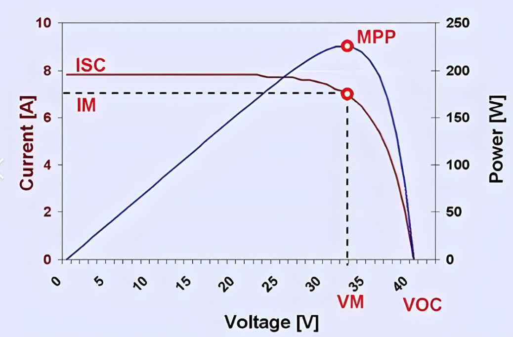
The functions you described (60V/10A, 5–60V adjustable, 100mA–10A adjustable, simulating a solar cell IV curve) correspond to a professional device called a Programmable Solar Array Simulator (SAS). It is also commonly called an IV curve simulation DC power supply.
Depending on whether you want to buy an off-the-shelf product or develop it yourself, here are three implementation options from different perspectives:
Option 1: Buy a Ready-Made Instrument (Most Recommended, Saves Time and Effort)
There are mature commercial products currently available on the market that meet your required 60V/10A (600W) specifications.
- Representative brands and models: Chroma 62000H series, ITECH IT-M3400 or IT6000 series, Keysight N8900 series, etc.
- Core advantages: Multiple standard IV curve models are built in (such as single-peak and double-peak). You only need to set V_{OC} (open-circuit voltage), I_{SC} (short-circuit current), and the maximum power point P_{max} on the screen, and the DSP inside the unit will calculate and output a smooth curve in real time.
- Note: When purchasing, make sure to distinguish between products. Some cheaper “programmable power supplies” on the market can only produce CV/CC turning points and cannot perform dynamic IV curve tracking. You must specifically choose a model designated as a “solar array simulator.”
Option 2: DSP-Based Custom DIY Solution (Self-Developed)
If you plan to design the circuit yourself, the core of the system lies in the power hardware circuit and the software control algorithm. You will need to solve the following key issues:
- Main Power Topology (Hardware Core):
- Since the output needs to be adjustable from 5V to 60V, if your input is 60V DC, you will need a buck or synchronous buck circuit.
- Note: Stepping 60V directly down to 5V/10A results in a very low duty cycle and serious efficiency problems. It is recommended that the front-end input voltage be around 70V–80V (with some margin), or that a Buck-Boost topology be used, so that both 5V and 60V can be output stably.
- Control Chip Selection:
- A high-speed DSP (such as TI’s C2000 series) or a high-performance MCU (such as STM32G4/F4) must be used.
- This is because the essence of an IV curve is “outputting a specific current at a given voltage” (or outputting a specific voltage at a given current).
- Core Algorithm (The Most Difficult Part):
- You need to include a lookup table (LUT) or a mathematical model formula (I = I_{ph} - I_0(e^{\frac{q(V+IR_s)}{nkT}}-1)).
- The difficulty lies in the controller’s dynamic response: when the load (such as an inverter or DC-DC converter) tries to draw power to search for the MPP (maximum power point), your power supply must switch extremely quickly between constant-voltage (CV) and constant-current (CC) modes. This requires high-performance dual-loop PI control (voltage loop + current loop); otherwise, the output will oscillate back and forth along the curve, or even lock directly at the open-circuit voltage or short-circuit point.
Option 3: Reverse Simulation Using an “Electronic Load” (Alternative Approach)
If you only have an ordinary programmable power supply and an electronic load, you can also use PC software to implement this.
- Method: Connect your DC power supply and electronic load in series or through a dynamic resistance. The PC software calculates the points on the IV curve in real time, then controls the current of the electronic load through a serial port or Ethernet port while monitoring the power supply voltage. A PID algorithm on the PC forces the operating point onto the curve. (The response speed is very slow, so this is only suitable for static testing.)
Practical Suggestions for Your Specified Parameters:
- Input power supply: If you want to DIY, the safest approach is to feed 220V AC mains power into a 600W AC-DC switching power supply (outputting about 72V/10A), and then use your DC-DC buck module to achieve a 5–60V output.
- Current ripple: At a 10A output, if the MPPT algorithm used to simulate the photovoltaic curve is not precise enough, the output current ripple can be very large. It is recommended to add sufficient LC filter capacitance at the output.
- Special note: The “output” of this type of device is different from that of an ordinary power supply. It is not a simple regulated voltage source. If you connect a multimeter to the output, the measured voltage will always be a dynamically changing value, because the algorithm is constantly searching for the maximum power point. This is completely normal.
Summary recommendation:
If it is for company R&D testing or a production line, it is strongly recommended to buy a ready-made unit, because developing a 600W high-frequency switching power supply with a complex closed-loop algorithm takes a very long time, and it is difficult for a DIY version to match the stability of commercial instruments. If it is for academic research or R&D practice, it is recommended to develop it around the core idea of Buck topology + DSP algorithm LUT lookup + dual-loop control.