I didn’t understand your question.
Source code is here
Still don’t understand what you’re asking.
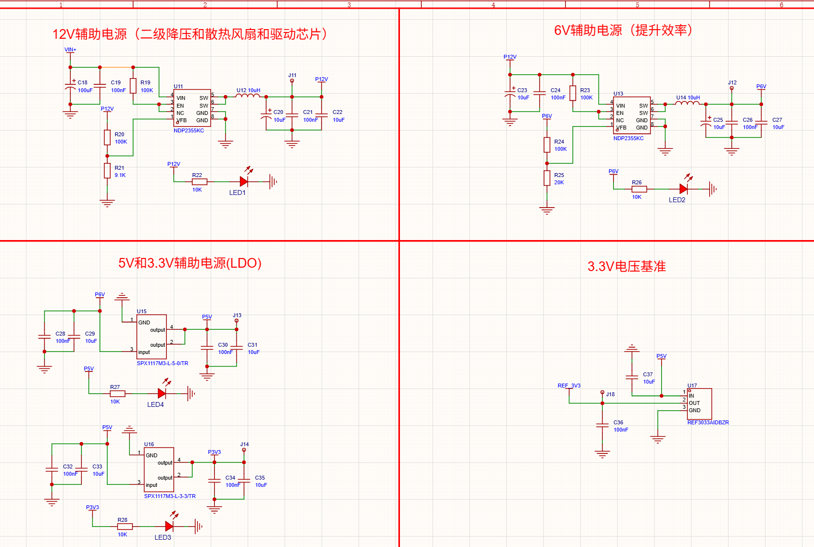
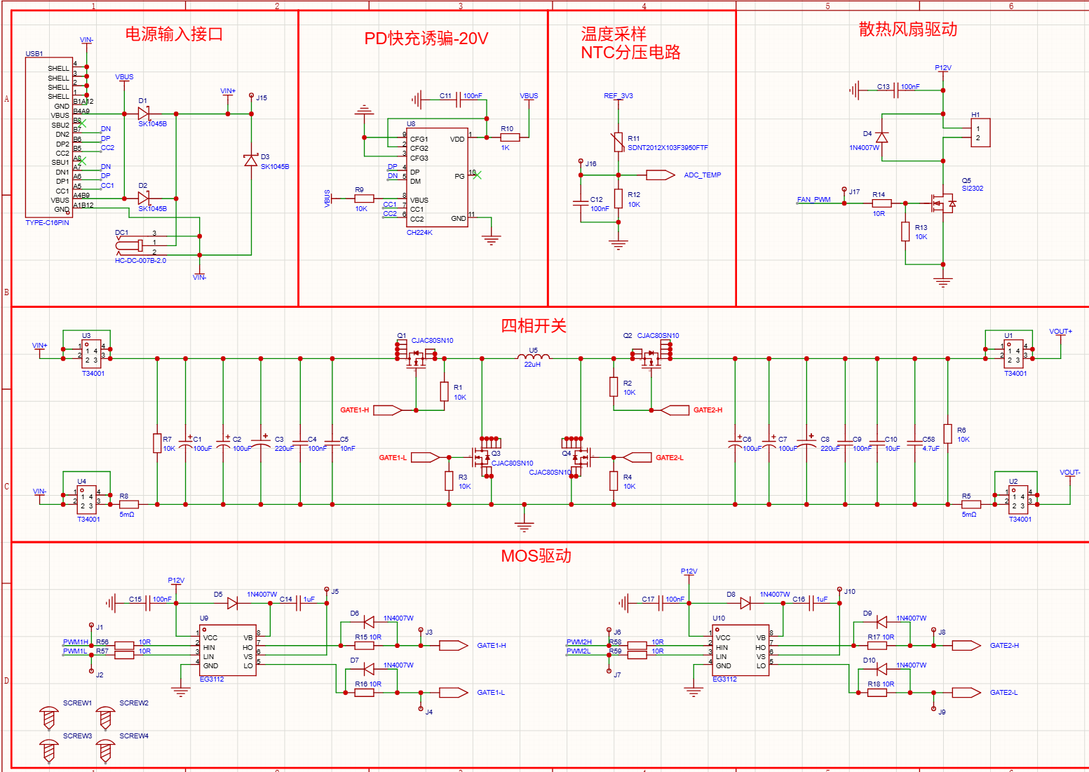
Blogger, could you please help me? I modified the auxiliary power module, replacing your DCDC step-down module with the NDP2355KC module. My power inductor is the PSPMAA0605H-100M-ANP. However, I’m encountering issues: when I input 16V or similar voltages and try to set the output to around 10V, the system restarts (when powered via the C port) or activates overcurrent protection, immediately outputting maximum current (when using a regulated power supply). When using a DC power supply, the supply enters CC mode with an output voltage of around 6V. Additionally, the MOSFET on the board overheats significantly. Could you help analyze this issue? Thank you!
Check if there’s a short circuit at the output
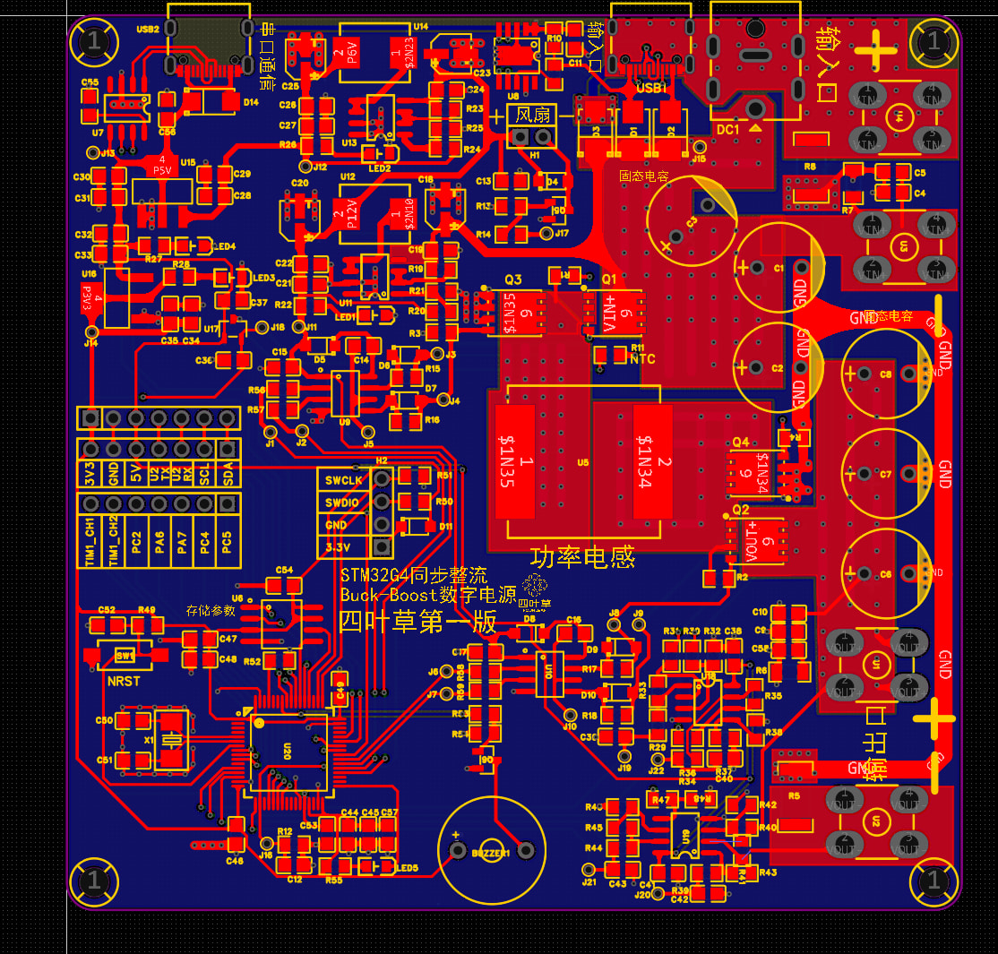
Take a look at your PCB layout
There is no short-circuit in the output either.
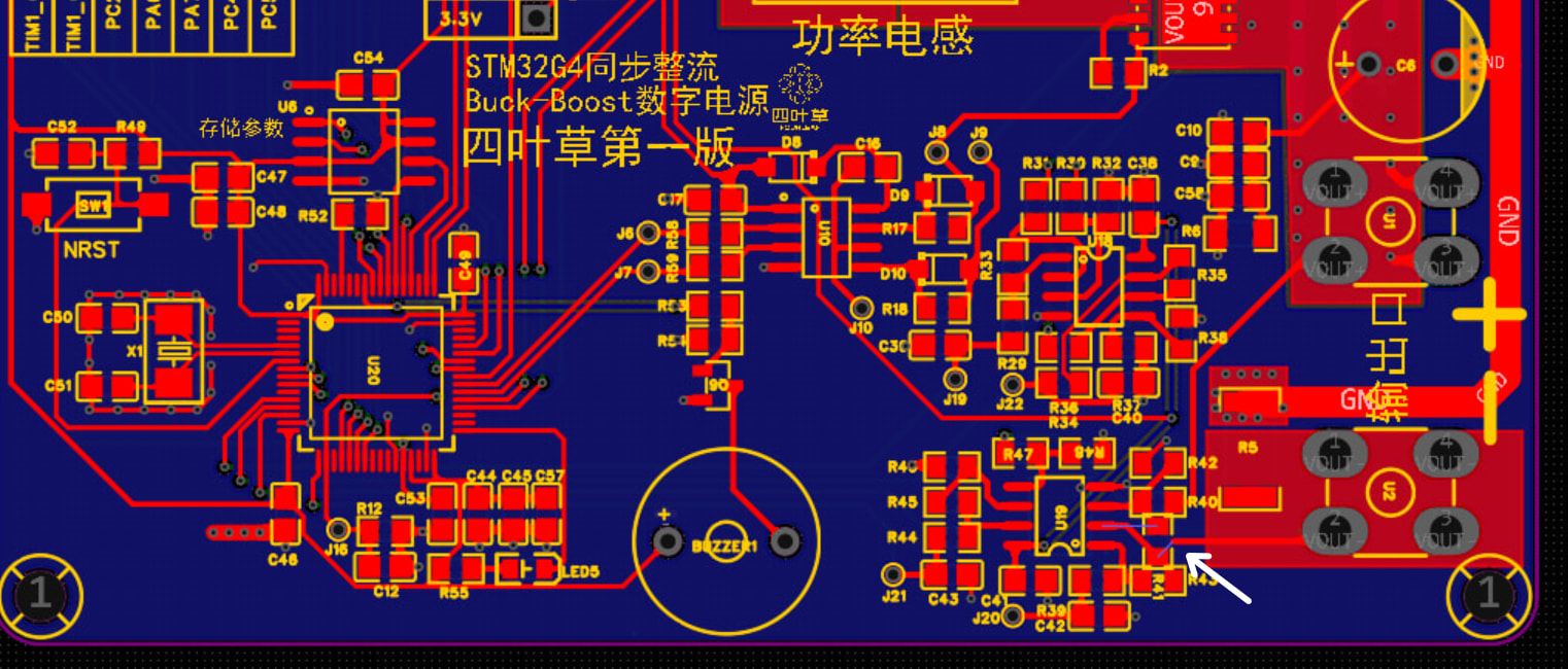
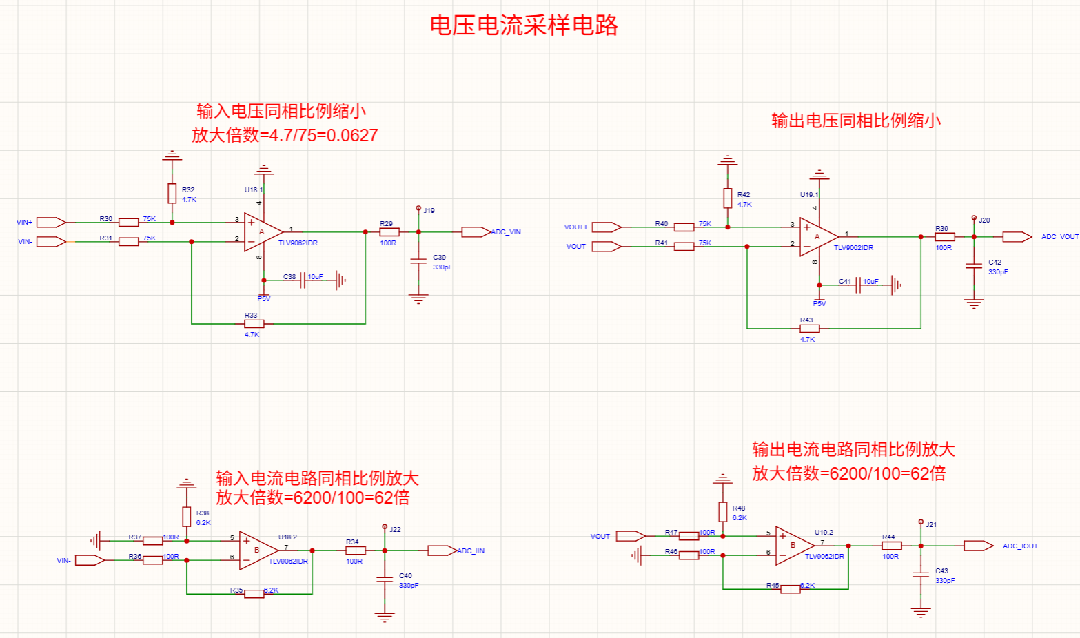
It’s just that the resistor was accidentally rotated slightly. The PCB is fine. I indeed didn’t notice that the current sensing should use Kelvin connections. Thanks to the blogger for the reminder.