What is an RC Filter Circuit?
An RC filter circuit is a simple filtering circuit composed of resistors (R) and capacitors (C) that can selectively process signals of different frequencies. In electronic circuits, we often need to retain specific frequency signals while attenuating others, and RC circuits provide the most fundamental implementation for this purpose.
Two Basic Types
1. Low-Pass Filter (LPF)
Function: Allows low-frequency signals to pass while attenuating high-frequency signals.
Circuit Structure: Input signal → Resistor → Capacitor → Ground, output taken across the capacitor.
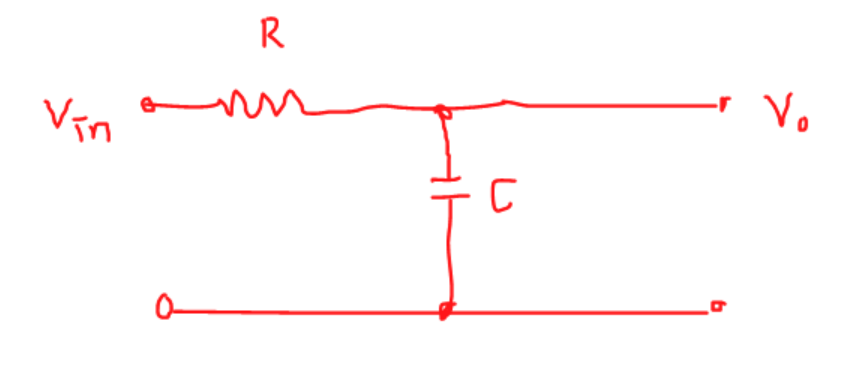
Working Principle:
- At low frequencies, the capacitor’s reactance is large, allowing almost all signals to reach the output
- At high frequencies, the capacitor’s reactance is small, shorting the signal to ground
- Effectively “blocks” high frequencies while “allowing” low frequencies to pass
2. High-Pass Filter (HPF)
Function: Allows high-frequency signals to pass while attenuating low-frequency signals.
Circuit Structure: Input signal → Capacitor → Resistor → Ground, output taken across the resistor.
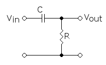
Working Principle:
- At low frequencies, the capacitor’s reactance is large, preventing signal passage
- At high frequencies, the capacitor’s reactance is small, allowing signals to pass smoothly to the output
- Effectively “blocks” low frequencies while “allowing” high frequencies to pass
Core Parameters and Calculations
Cutoff Frequency (f₀)
This is the most important parameter of a filter, representing the frequency at which the signal attenuates to -3dB (approximately 70.7% of the original amplitude).
Formula:
f₀ = 1 / (2πRC)
Where:
- R: Resistance value in ohms (Ω)
- C: Capacitance value in farads (F)
- π: Pi constant, approximately 3.1416
Calculation Example
Suppose we need to design a low-pass filter with a cutoff frequency of 1kHz:
Select R = 1kΩ = 1000Ω
Calculate required capacitance:
C = 1 / (2π × R × f₀)
  = 1 / (2 × 3.1416 × 1000 × 1000)
  ≈ 0.000000159 F = 0.159 μF
In practical applications, we can choose the closest standard value of 0.15μF or 0.22μF.
Frequency Response Characteristics
Attenuation Slope
- Beyond the cutoff frequency, signals attenuate at 6dB per octave
- This means the signal amplitude halves for every doubling of frequency
Phase Shift
- Low-pass filter: Output signal phase lags input
- High-pass filter: Output signal phase leads input
- At cutoff frequency, phase shift is exactly 45°
Practical Application Considerations
- Load Impedance Impact: Actual load connections will alter filter characteristics, requiring load impedance consideration
- Component Precision: Resistor and capacitor precision directly affects filter performance
- Frequency Range: RC filters suit audio to mid-frequency ranges; extreme frequencies require alternative solutions
- Cascading Use: Multiple RC stages in series can achieve steeper attenuation characteristics
Summary
RC filter circuits are among the most fundamental and important circuits in electronics. Through simple resistor-capacitor combinations, they achieve frequency selection capabilities. Mastering RC filter principles and calculations forms the basis for understanding more complex filters and signal processing systems.
Remember the key formula f₀ = 1/(2πRC), and you can design filters meeting basic requirements!