一、RC去抖核心原理与取值原则
按键机械去抖的本质是利用RC阻容电路的充放电惰性,平滑按键闭合、断开时的电压毛刺,滤除机械抖动。常用电路为上拉电阻R并联电容C在按键两端,其核心参数是RC时间常数:
\boldsymbol{\tau = R \times C}
- \tau:RC时间常数,单位秒(s),代表电容电压充/放电至稳态值的63.2%所需时间;
- 工程上认为电路达到99%以上稳态、完全滤除抖动,需要 \boldsymbol{5\tau} 的时间;
- 普通轻触按键的机械抖动时长为5~20ms,为保证可靠去抖,需满足 \boldsymbol{5\tau \ge 20ms} ,即 \boldsymbol{\tau \ge 4ms} 。
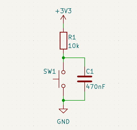
二、10kΩ上拉电阻的电容推荐取值
已知上拉电阻 R=10\mathrm{k}\Omega=10\times10^3\Omega ,结合 \tau\ge4\mathrm{ms}=4\times10^{-3}\mathrm{s} 的要求,推导最小电容:
C_{\text{min}} = \frac{\tau}{R} = \frac{4\times10^{-3}}{10\times10^3} = \boldsymbol{400\mathrm{nF}}
结合电子元器件标准标称值,10kΩ上拉电阻的电容推荐如下:
| 电容标称值 | 对应RC时间常数 \tau | 5\tau 完全去抖时间 | 适用性 |
|---|---|---|---|
| 220nF | 2.2ms | 11ms | 滤波效果偏弱,仅适合抖动极小的优质按键 |
| 470nF | 4.7ms | 23.5ms | 满足绝大多数按键去抖需求,是工程常用搭配 |
| 1μF | 10ms | 50ms | 去抖效果强,但按键响应变慢,适合对响应速度不敏感的场景 |
结论:使用10kΩ上拉电阻,优先选择470nF电容,兼顾去抖效果与按键响应速度。
三、10kΩ电阻+470nF电容的充放电时间计算
代入公式精确计算:
- RC时间常数
\tau = R \times C = 10\times10^3\,\Omega \times 470\times10^{-9}\,\mathrm{F} = \boldsymbol{0.0047\,\mathrm{s} = 4.7\,\mathrm{ms}}
- 完全充放电、可靠去抖时间
电路达到99%以上稳态,需 5\tau :
5\tau = 5 \times 4.7\,\mathrm{ms} = \boldsymbol{23.5\,\mathrm{ms}}
该时间远大于普通按键20ms的最大抖动时长,能够完全滤除机械抖动,同时不会造成明显的按键延迟。
四、实际应用补充说明
- 电容优先选用独石电容、陶瓷电容,稳定性好、成本低,避免使用电解电容(有极性、高频特性差);
- 若单片机IO口内部集成上拉电阻,外部可省去10kΩ上拉,直接在按键两端并联电容即可;
- RC硬件去抖属于无源滤波,无法完全消除极端抖动,对高可靠场景,可搭配软件延时去抖(读取IO电平后延时10~20ms再次读取),实现双重去抖。