Simple Discrete Operational Amplifier Circuit Diagram

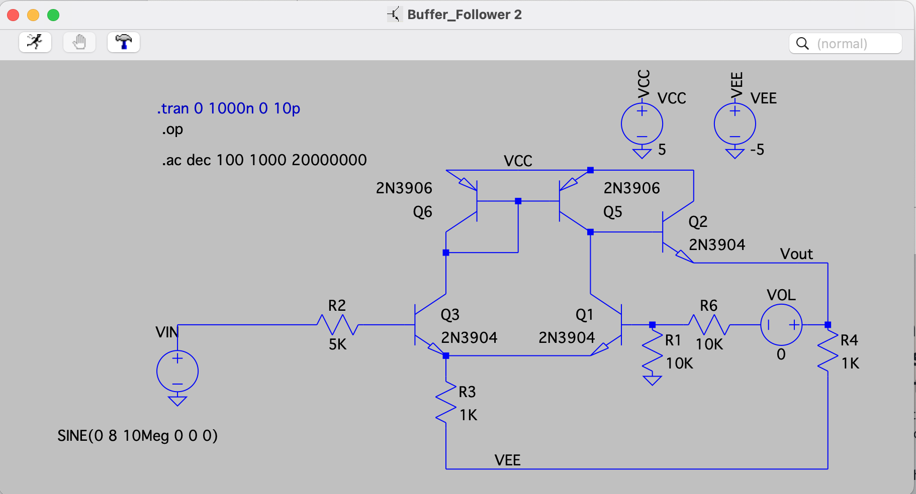
Here is a simple operational amplifier composed of 5 transistors and 2 resistors, which may help some people learn about the internal working principles of transistor operational amplifiers.

Of course, this operational amplifier has performance issues such as large offset voltage, high bias current, low open-loop gain, narrow bandwidth, and poor output stage performance. Any operational amplifier costing $0.10 on the market will outperform this one, but as a discrete component circuit, its structure is simple enough to serve as an excellent learning tool for those wanting to explore the internal workings of operational amplifiers rather than treating them as a “black box.”

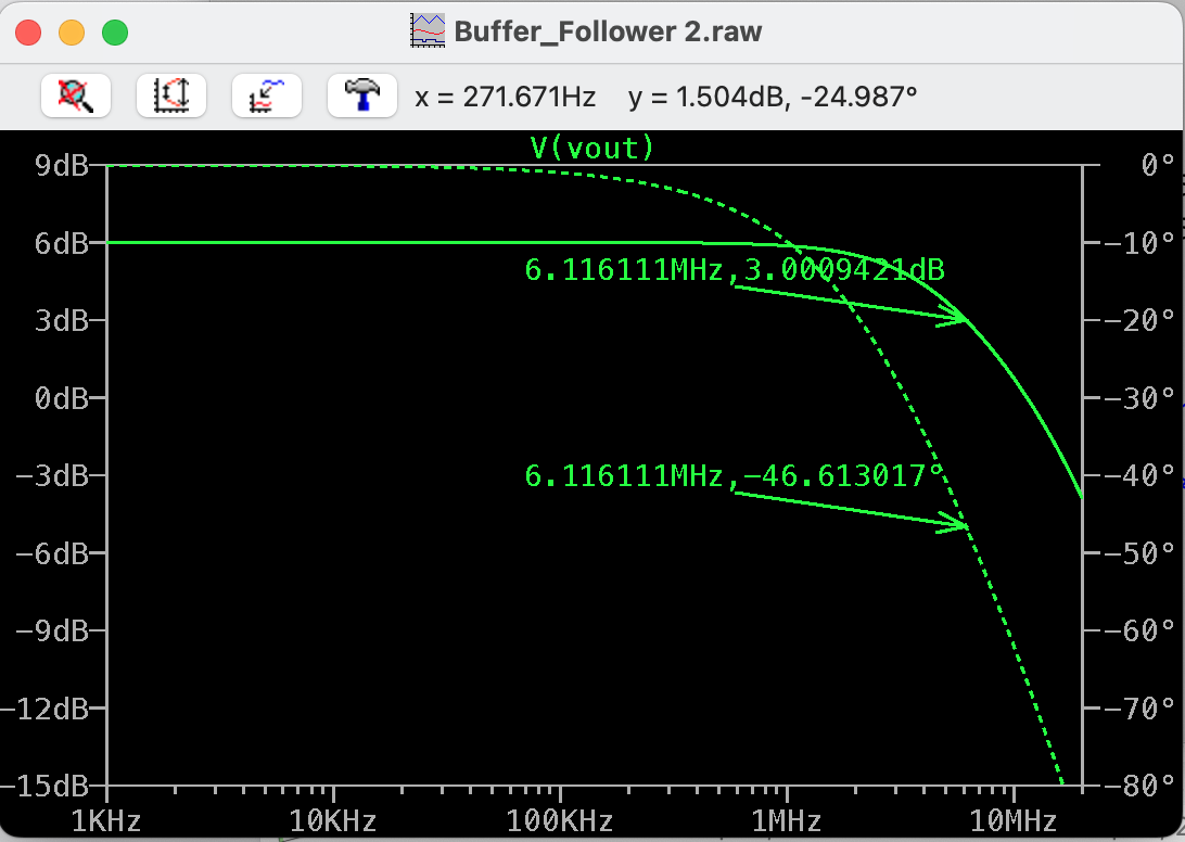
Most transistors can be used to build this circuit. We selected 2N3904 and 2N3906 transistors paired with two 1kΩ resistors. The core circuit only requires a ±5V power supply to operate. The circuit uses a pair of 10kΩ resistors for feedback, configured in a non-inverting amplifier setup with a gain of 2 (6dBV).

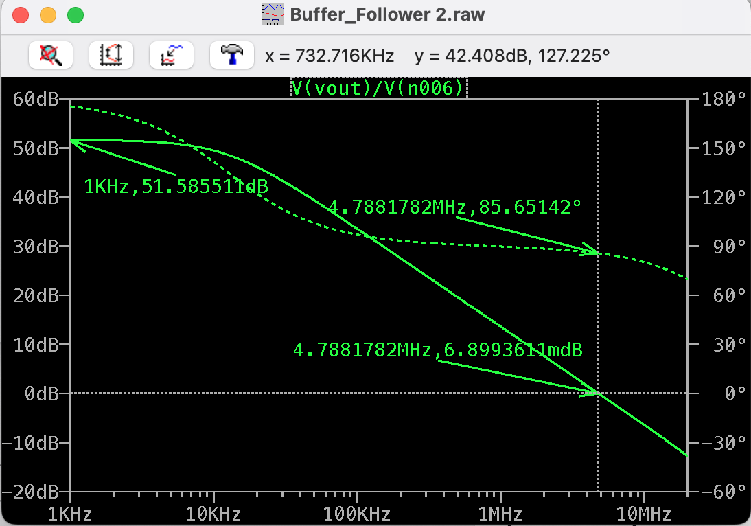
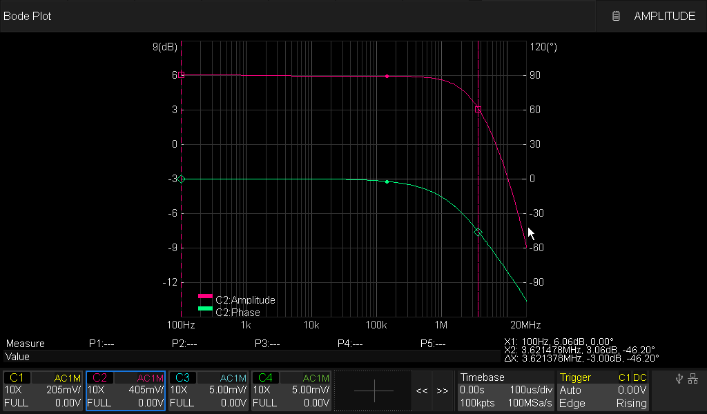
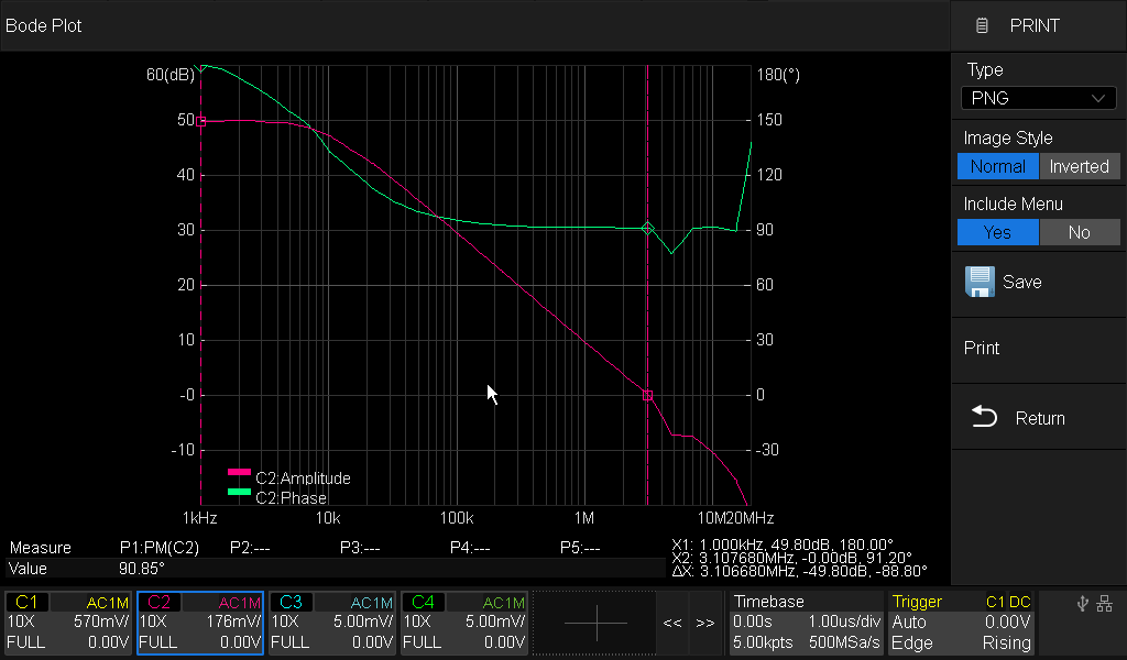
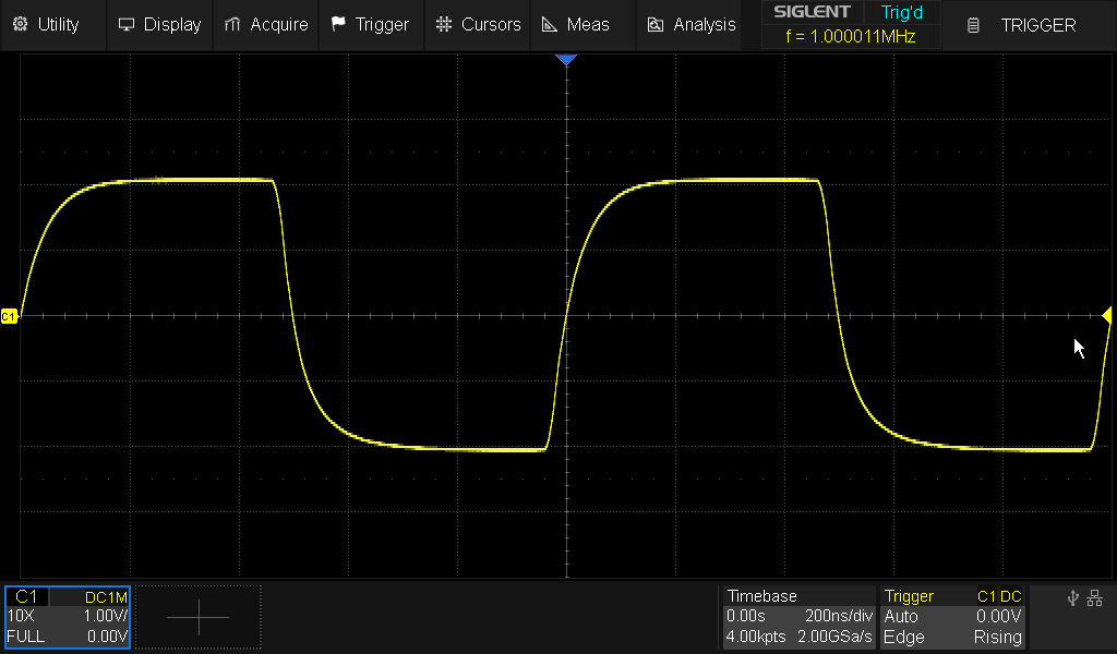
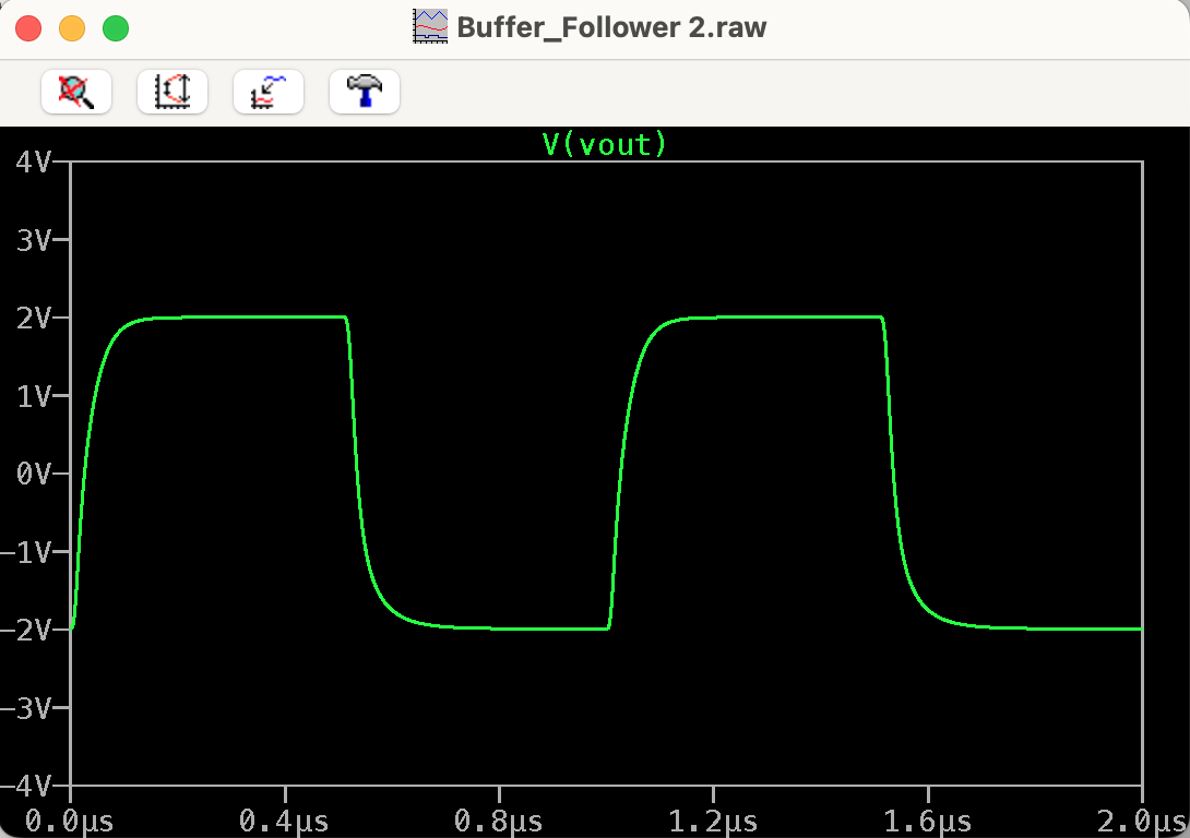
The article includes simulation results based on the LTspice default model, as well as actual circuit test response data — test results show the circuit achieves the previously mentioned 2x gain, and an isolation transformer was used during the open-loop tests for the measurements.

Please note that in the LTspice schematic, VOL is a test voltage source used to measure open-loop gain, and in actual measurements, the secondary winding of the isolation transformer is also connected at this position.

We hope you find some enjoyment from this circuit.

11e683cf681f3deec1fa2a67ac369d29__action=dlattach;attach=2293489;image
cbc3243d9da47446d1c37b9d9068b486__action=dlattach;attach=2293493;image
d19835ea4895d5ef3ace4d4c0c61c6a6__action=dlattach;attach=2293501;image
b8485e2cba67088b596026390816c3ad__action=dlattach;attach=2293505;image
c4d699f8c800a29a8710097a6e42e9ea__action=dlattach;attach=2293519;image
629bca45a291cc6984c76eb3f64162fb__action=dlattach;attach=2293693;image
db7498b9b5bb996a8d91d47ca98c3ef1__action=dlattach;attach=2293697;image

2 Likes

The architecture of this amplifier is indeed quite basic. Its output range is constrained by the input common-mode voltage: the output voltage cannot be much lower than the input voltage (approximately 1V). Therefore, the circuit should actually incorporate an additional amplification stage.

To simplify the circuit, the current mirror can also be eliminated by implementing a constant current source for the differential pair (LTP), which would at least maintain a certain level of common-mode rejection capability.

Additionally, the circuit lacks a frequency compensation stage.

1 Like

As previously stated, the core purpose of this circuit is to help beginners understand the operational amplifier’s fundamental working characteristics through the process of improving this simple circuit.

I made a breadboard version of the 5BJT version, and it works more or less like the LTSpice version, as a diff. amp it makes a nice since wave between 0-3.6V. But I’m surprised how quick the output starting dropping off past 10kHz, I don’t think I had any extra capacitance of any size. I need to make the AC model, see what it looks like.

None of my textbooks go into enough detail on this stuff, I guess I need higher level books. I just buy old old textB’s, but in good shape.