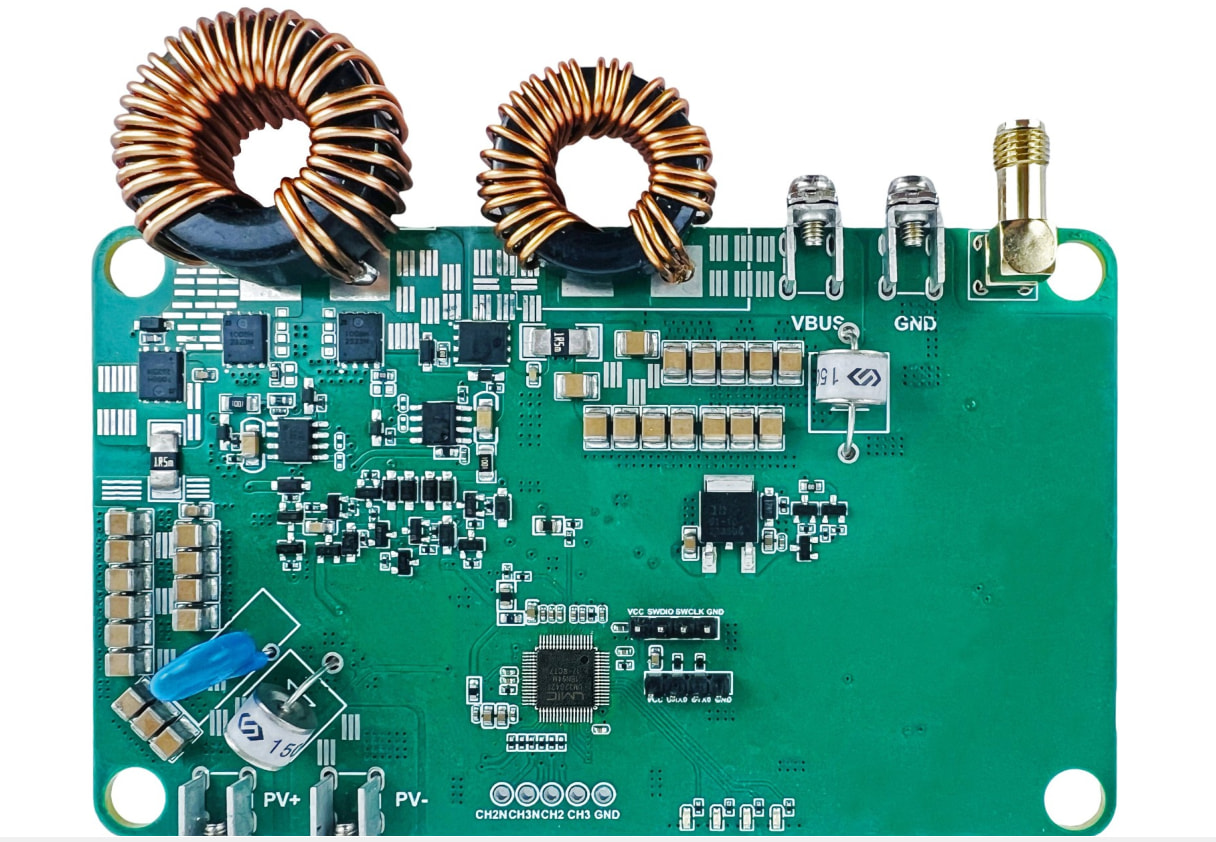
Why do MPPT products usually have two inductors?

The large inductor in the middle of the H-bridge is the main power inductor. Together with the four MOSFETs, it forms a four-switch Buck-Boost (synchronous step-up/step-down) topology. MPPT has to handle various voltage differences between the solar panel and the battery, and this large inductor is mainly responsible for energy storage and conversion. It needs to withstand very high ripple current, which is why you can see that its wire gauge is very thick and the magnetic ring is large.

As for the small inductor between the H-bridge output and VBUS, it is clearly used for output filtering. Together with the SMD capacitor next to it, it forms an LC low-pass filter. Batteries or the VBUS side are usually quite sensitive to high-frequency ripple, so adding a second-stage filter can effectively reduce switching noise and make it much easier to deal with EMC testing. The components used are fairly solid.

Judging by the trace topology, this should be a typical four-switch synchronous Buck-Boost architecture. The large toroidal inductor in the middle of the H-bridge is the main power inductor, responsible for the core energy storage and energy transfer when the switching transistors operate. The small inductor at the output of the H-bridge is essentially paired with the capacitor network downstream to form a second-stage LC filter (or a pi filter). During MPPT optimization, the current can vary significantly, so relying on the main inductor alone is not enough to ensure sufficiently low voltage ripple at the VBUS output. Adding a small-value inductor specifically to suppress high-frequency switching noise is a common practice for improving power supply output quality.

One large and one small, each with a different role.
Large inductor: main power energy storage for the four-switch buck-boost converter.
Small inductor: high-frequency filtering/choking at the output.

It mostly comes down to power quality and EMI compliance. The central large inductor is obviously your main buck-boost component. However, the hard switching of the 4 MOSFETs in the H-bridge generates substantial dI/dt and high-frequency harmonics. You really don’t want those transients propagating down the VBUS line and polluting the rest of the system. That smaller inductor is essentially an EMI/ripple choke, knocking down the high-frequency spikes before they can leave the power stage.