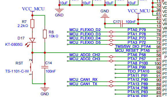
This is the schematic for the Elephant Embedded S32K144. The current issue is that the program won’t run, and the flash remains empty. RESET measures 1 V to ground when the reset button is released, which is clearly wrong.
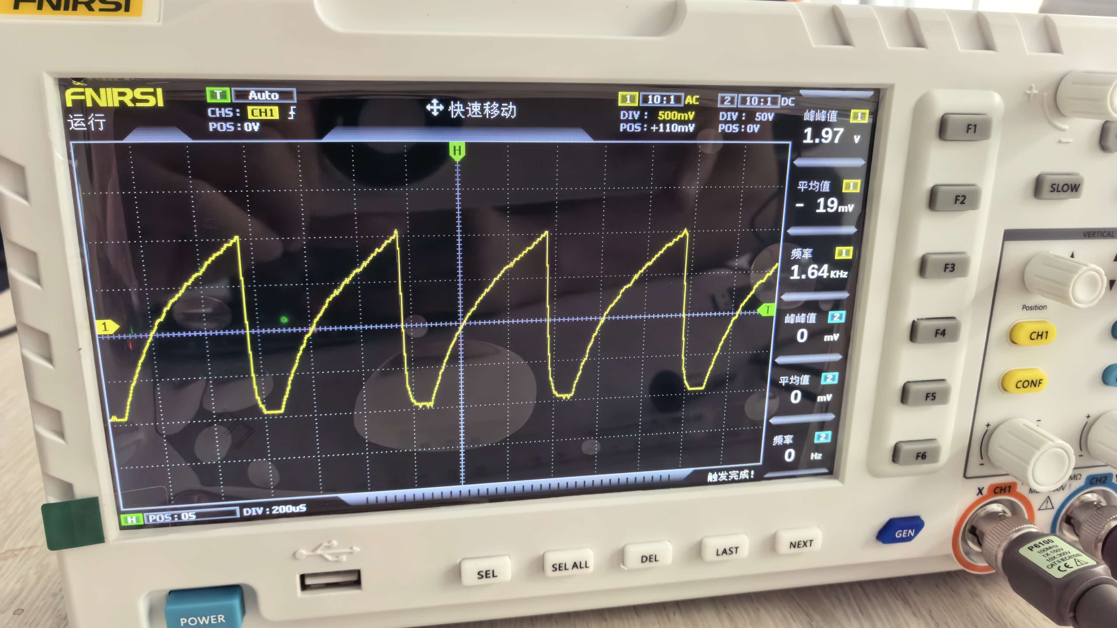
The seller’s view is that the chip is locked and RESET will have an output. Below is the RESET-to-ground waveform.
But after I walked GPT through the flashing process, it told me the chip isn’t locked: the flash can be programmed, but it is immediately erased.
When I gave GPT the entire process, its explanation was: the chip’s reset loop is not a watchdog, but a LOCKUP reset—an empty flash CPU fetches instructions at 0xFFFFFFFE → bus error → HardFault (the handler is also at 0xFFFFFFFE) → recursion → LOCKUP → reset → repeat, with a period of a few hundred microseconds.
However, none of the suggested fixes worked. Do any of you experts know how to resolve this?
Is the reset IO being repeatedly pulled low? Could it be that the program you flashed uses PTA5 (RST) as an IO, pulls this IO low in software, and doesn’t disable the reset function of this IO in software, causing continuous resets and reboots? Try flashing a normal example program.
The 1 V RESET voltage on this board really does seem problematic. Normally, after the reset button is released, RESET should be pulled close to VCC (3.3 V) by an internal pull-up or an external pull-up resistor. A reading of 1 V means either the pull-up is too weak, or the chip itself is continuously pulling the reset line low.
Looking at your schematic, the R7 2.2 kΩ pull-up should be strong enough, but note that the RESET pin on the S32K144 is bidirectional—the chip itself can also actively pull reset low. If it really is stuck in a LOCKUP loop, the chip will reset itself every few hundred microseconds, and the 1.64 kHz sawtooth waveform you see on the oscilloscope is very likely that.
First, check a few things:
-
Measure the voltage across R7 to confirm that the pull-up resistor is actually connected to VCC_MCU and that the voltage is normal. Sometimes a dry solder joint on the development board power supply or an unstable LDO output can cause the pull-up voltage to be insufficient.
-
Disconnect the reset button and connect the RESET pin directly to VCC with a jumper wire, then see whether the program can run. If it does, the issue is in the reset circuit; if it still does not, you can rule out the reset circuit.
-
Connect directly with a J-Link or PE debugger, without going through the onboard OpenSDA, and see whether it can identify the chip ID. Sometimes the onboard debugger can interfere with reset.
-
Check VDDA and VREFH. If the S32K144 analog power supply is unconnected or unstable, it can also cause strange reset behavior.
As for the LOCKUP loop mentioned by GPT, the logic is correct—an empty flash can indeed cause this. But the key question is why the flash is empty. Did the programmer fail to write it, or was it written and then erased? I recommend connecting to the chip directly with J-Flash or S32 Design Studio and checking what the flash content actually is. If the flash is indeed all FF, first write the simplest possible blink program to it and see whether it can run. If it runs, the chip is not locked and the issue is with the programming flow; if it still does not run, then consider whether the chip is damaged or locked.
The GPT explanation is actually spot on. An empty flash on the S32K144 causes a fetch from an invalid address, leading to a HardFault, which escalates to a Lockup and then a system reset. The MCU is actively driving that reset pin low, hence the 1.64kHz sawtooth waveform you’re seeing. To fix this, you need a debugger that supports “Connect under reset”. If you’re using a J-Link, open J-Link Commander and try the unlock kinetis command. It halts the core before it tries to execute the bad instruction.
Same board. I ran into this exact issue last month. Your GPT analysis is actually pretty accurate: it’s a LOCKUP loop. But don’t be misled by the reset waveform.
What worked for me was: press and hold the reset button while programming, then release it immediately after clicking Download. This lets the code get written before the chip comes out of reset. Once it enters a LOCKUP loop, the SWD timing gets scrambled; the debugger thinks the write succeeded, but it never actually wrote anything. If you read it back later, it’s all 0xFF, which makes it look like it was “erased.”
Also, check whether your startup file is specifically for the S32K144. If you ported the code from STM32, the vector table location or linker script may be wrong. The S32K144 Flash starts at 0x0000_0000, but the vector table must contain a valid initial SP and Reset_Handler. If either of those values is 0xFFFFFFFF, the chip will jump straight into HardFault as soon as reset is released.
One more thing: measure whether the 3.3 V supply is stable. This board sometimes can’t handle USB power properly. If the voltage drops below 2.8 V, Flash writes can fail silently, which also looks like it “won’t program.” Try using a shorter USB cable or an external 5 V supply.
Is it a new board? It could also be continuously resetting because there’s no program on it.
I had the same issue when I used an ESP32S3 before. With a new module, the flash memory is empty, so it keeps triggering a reset. The solution for the ESP32 is to power it on while holding the BOOT button to enter flashing mode.
The leader gave it to me. He said he hadn’t used it before.
I used the official example and checked PTA5, but it wasn’t configured.
I tried it, and unlocking Kinetis works, but the flash still can’t be written to—or rather, it gets written and then erased again.
Thanks, I’ll try it tomorrow morning.