Gongtian F95D Portable Mini Fan Teardown Analysis and Circuit Analysis.
I recently bought a small fan with 4 speed settings, 18W fast charging, a 5000mAh battery, and a USB-C port that supports both input and output, so it can also be used as a power bank. In this article, I’ll take it apart and analyze the circuit.
Other teardown articles: https://blog.zeruns.com/tag/拆解/
Product Specifications
- Product name: Portable multifunction charging fan
- Product model: F95D
- Power: 8W
- Product weight: 222g
- Battery capacity: 5000mAh
- Runtime: 2–24h
- Main unit dimensions: 106×43×140mm
- Package dimensions: 109×46×178mm
Purchase link: https://s.click.taobao.com/nVQY0qj
Fan Appearance
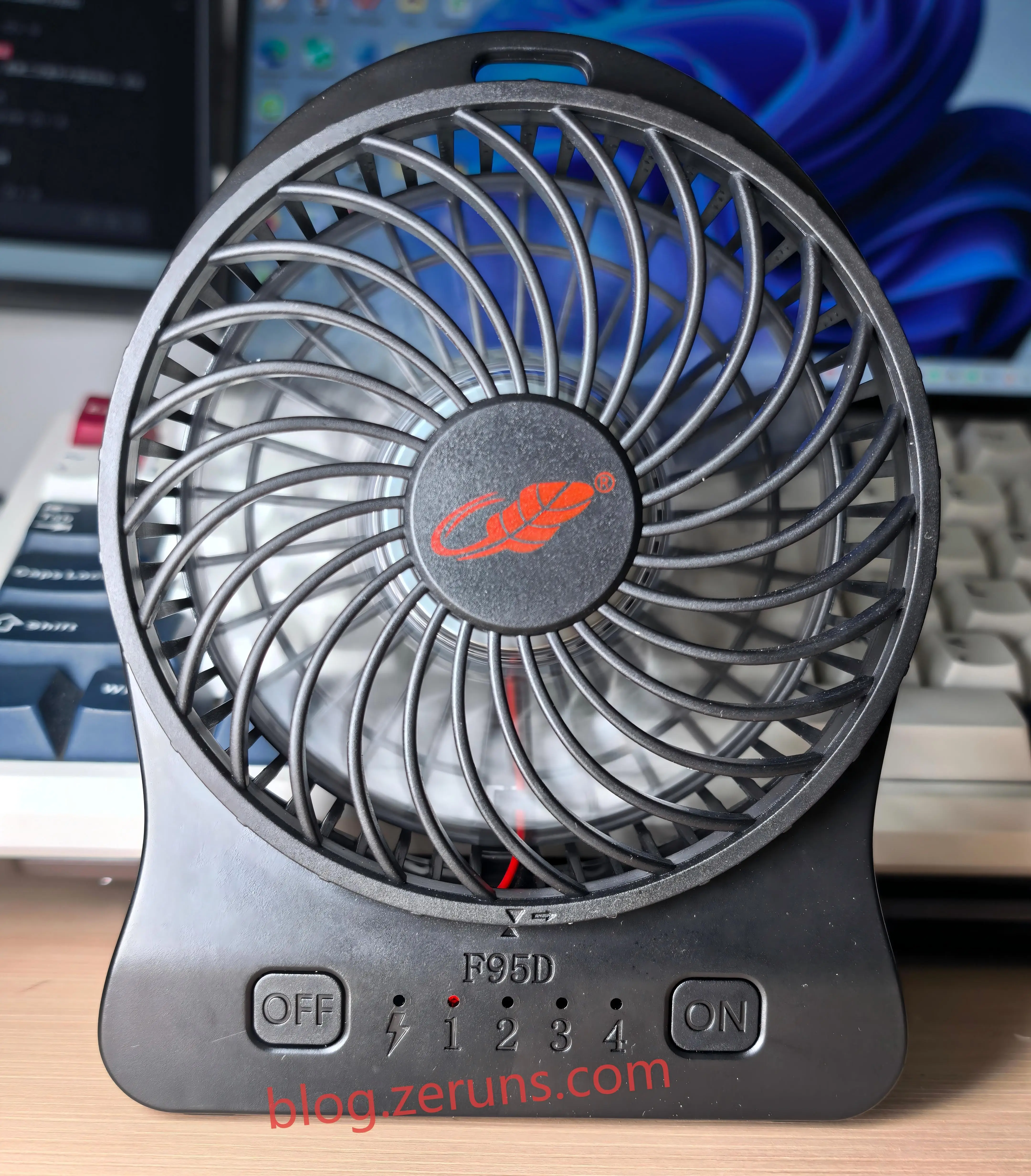
Front view of the fan. There are two buttons on the front: OFF on the left and ON on the right. Each press of the ON button increases the speed by one level. In the fourth-speed state, pressing ON again turns the fan off directly. Pressing OFF at any speed level turns the fan off directly. In the middle, 4 red LEDs + 4 green LEDs indicate the speed level and battery level respectively. The green battery-level LEDs only light up while charging. To the left of the level-1 indicator is a blue LED with a lightning symbol, which is the fast-charging indicator; it only lights up when fast charging is triggered.
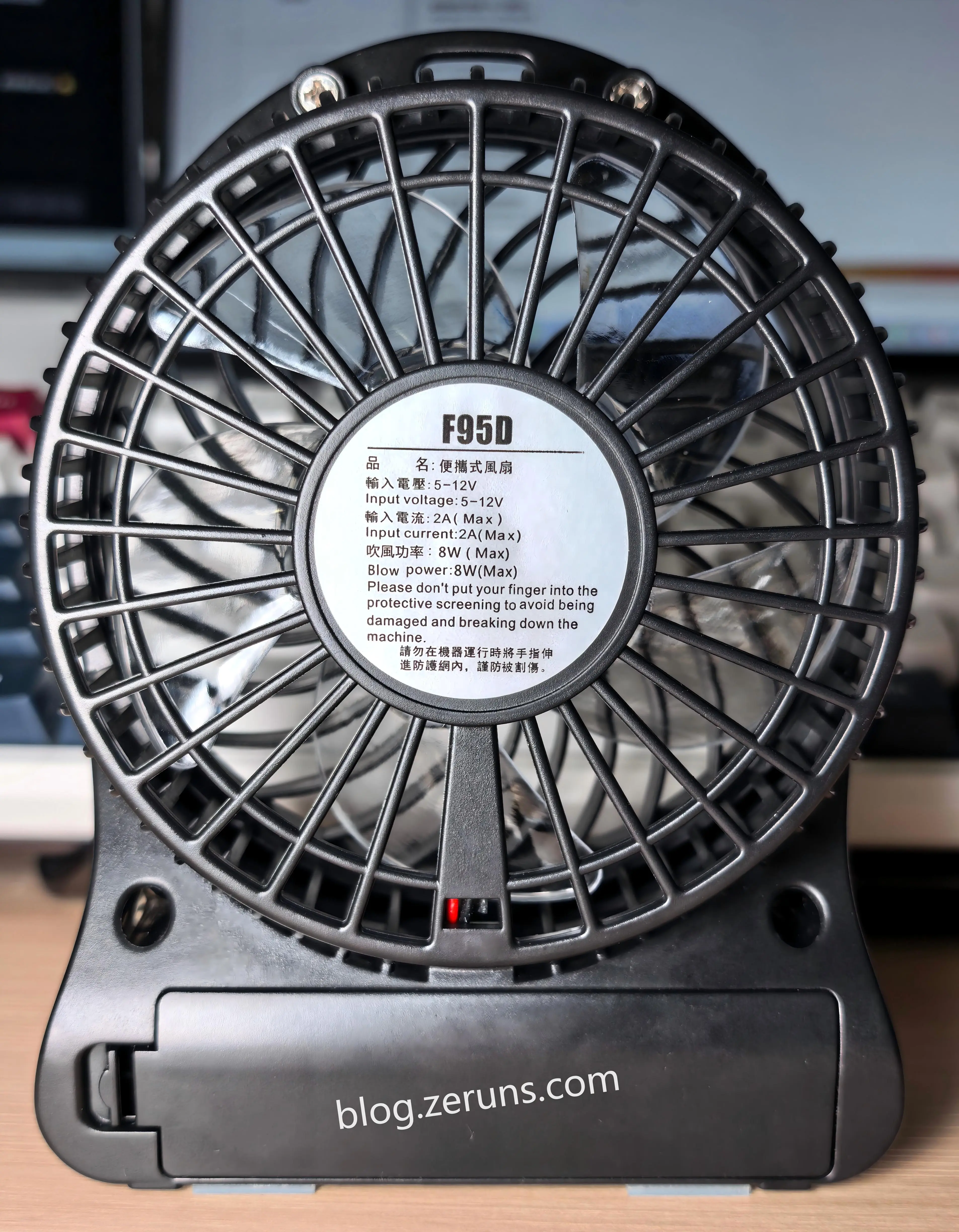
Back view of the fan. There is a label in the middle, with specifications printed in Chinese and English. The Chinese text uses traditional characters:
- Product name: Portable fan
- Input voltage: 5–12V
- Input current: 2A (Max)
- Blowing power: 8W (Max)
- Do not insert fingers into the protective grille while the device is running, as this may cause injury.
The bottom is the battery compartment, which supports 21700 and 18650 ternary lithium batteries.
Charging Power and Heat Test
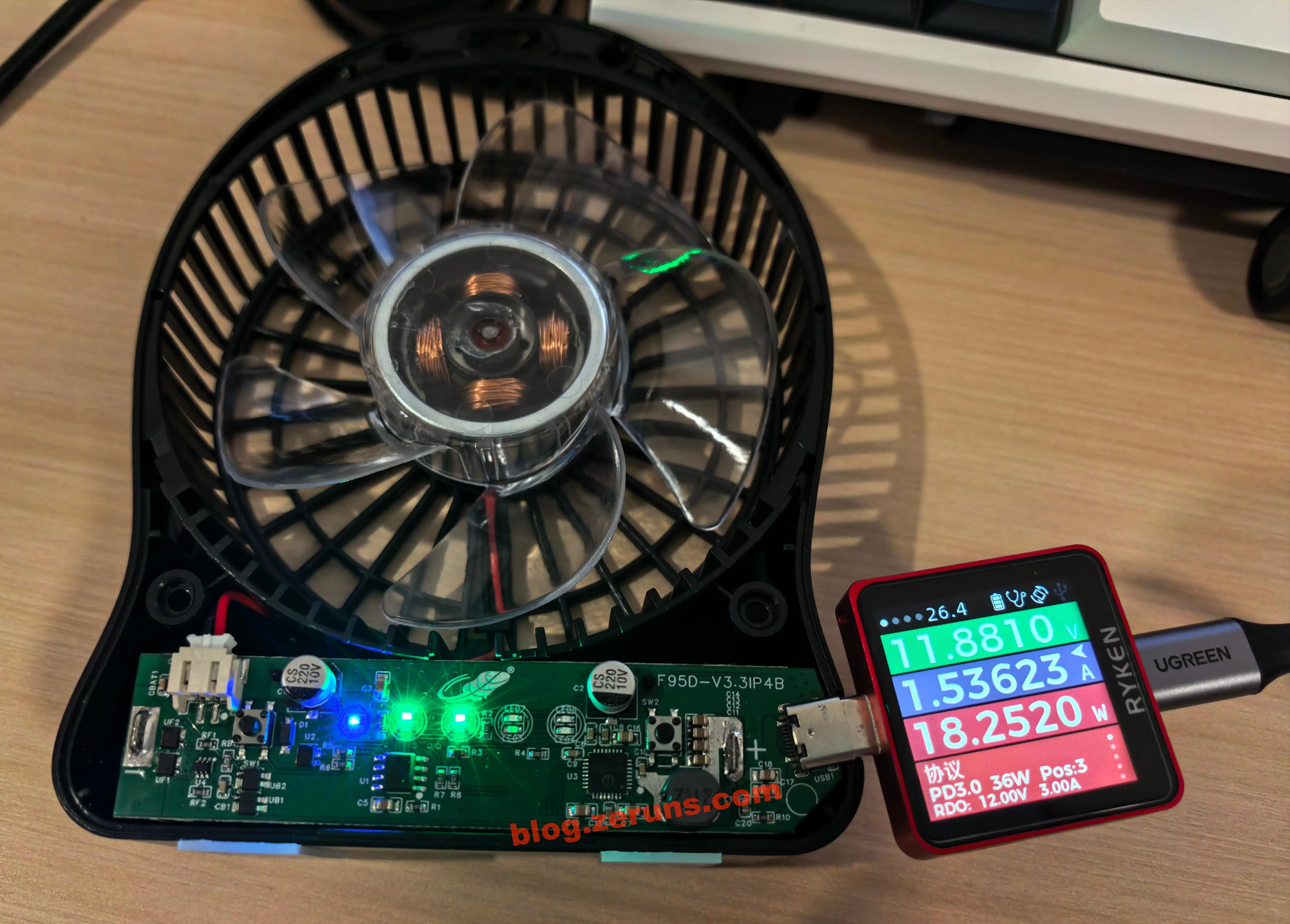
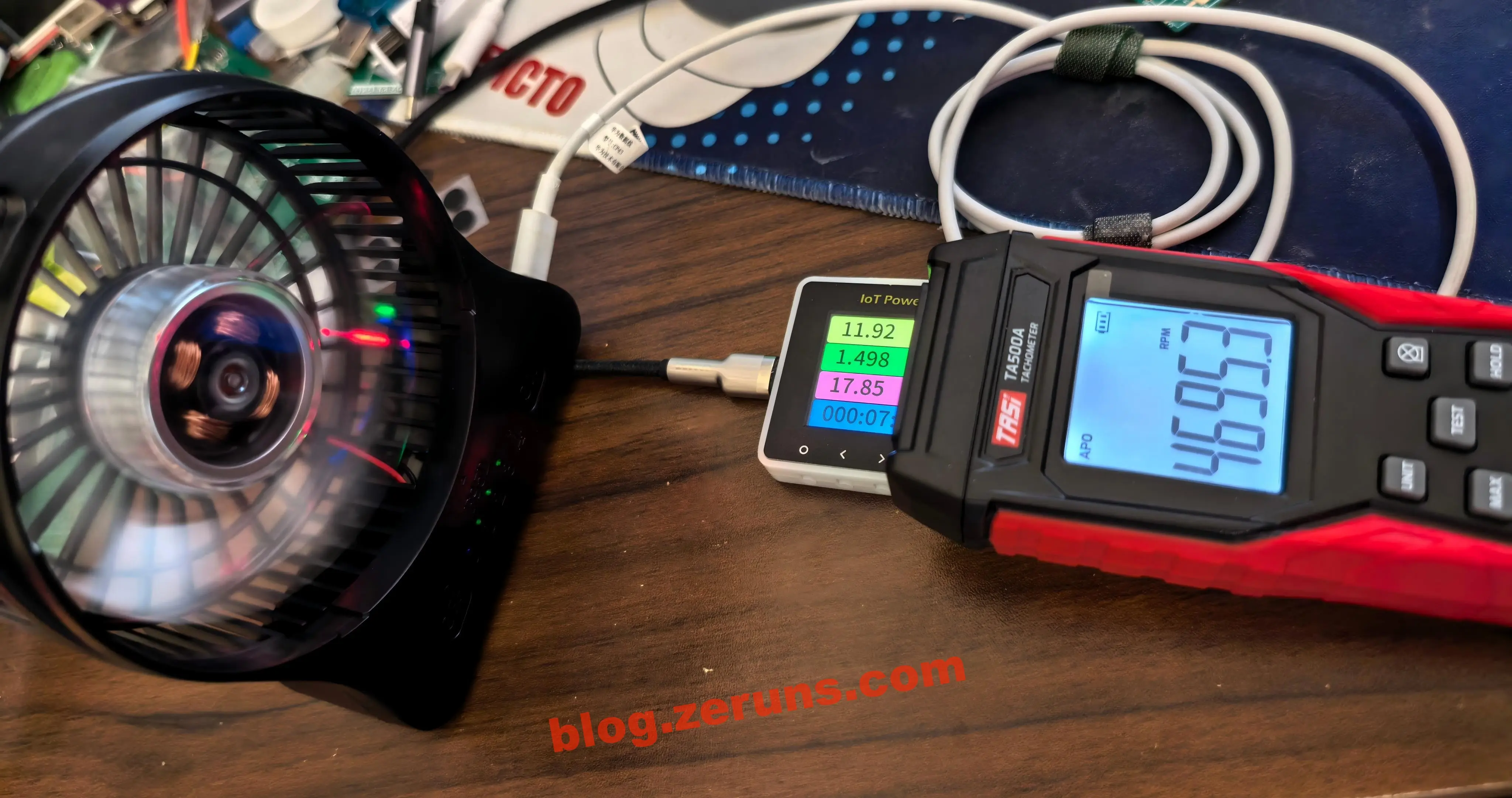
The charger is a Huawei 100W fast charger that supports the PD fast-charging protocol. The fan battery was at 2 bars, and the measured charging power was about 18W, with a requested voltage of 12V.
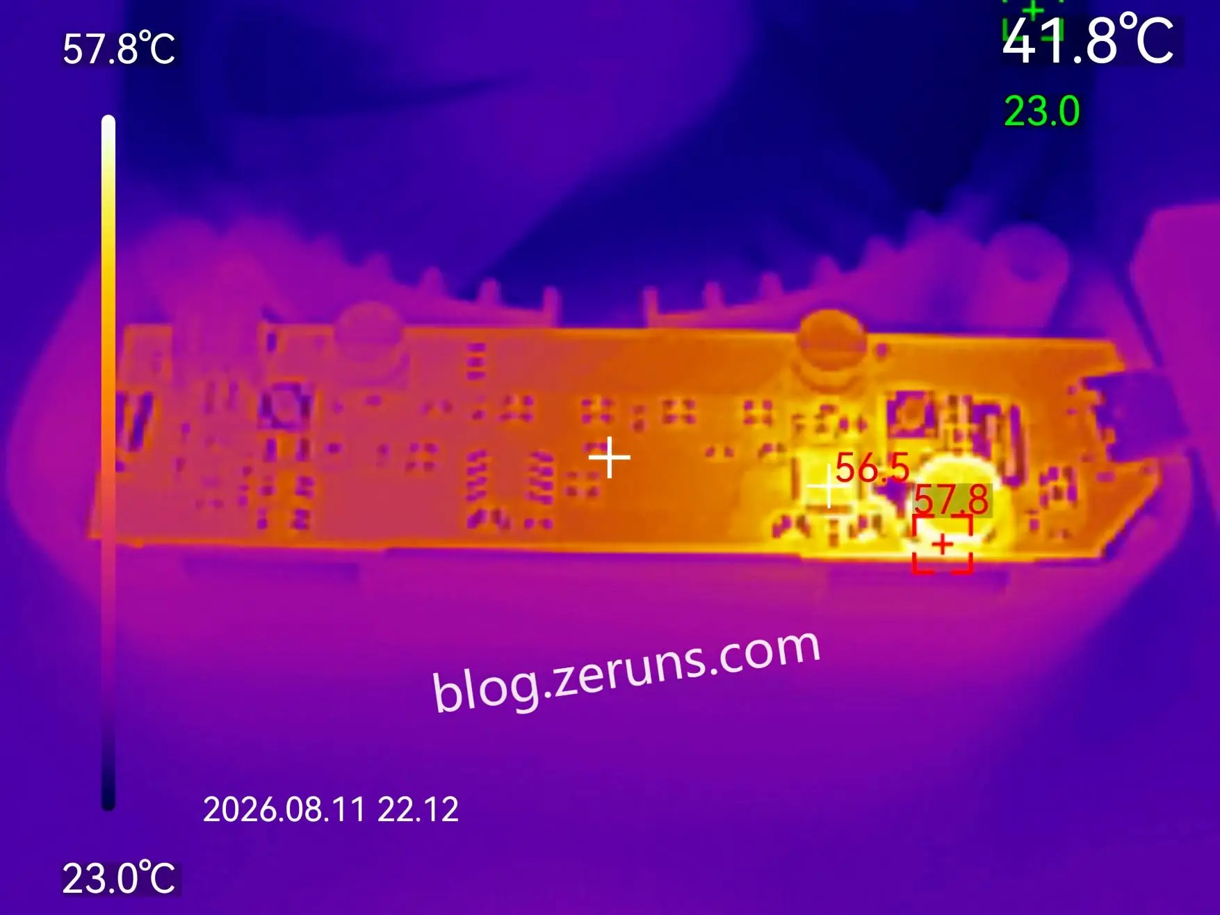
The following is a thermal image of the front side of the circuit board after ten minutes of charging. The ambient temperature was about 23°C. The charging chip temperature was about 56.5°C, and the temperature of the charging chip’s DC-DC inductor was about 57.8°C.
Speed Test
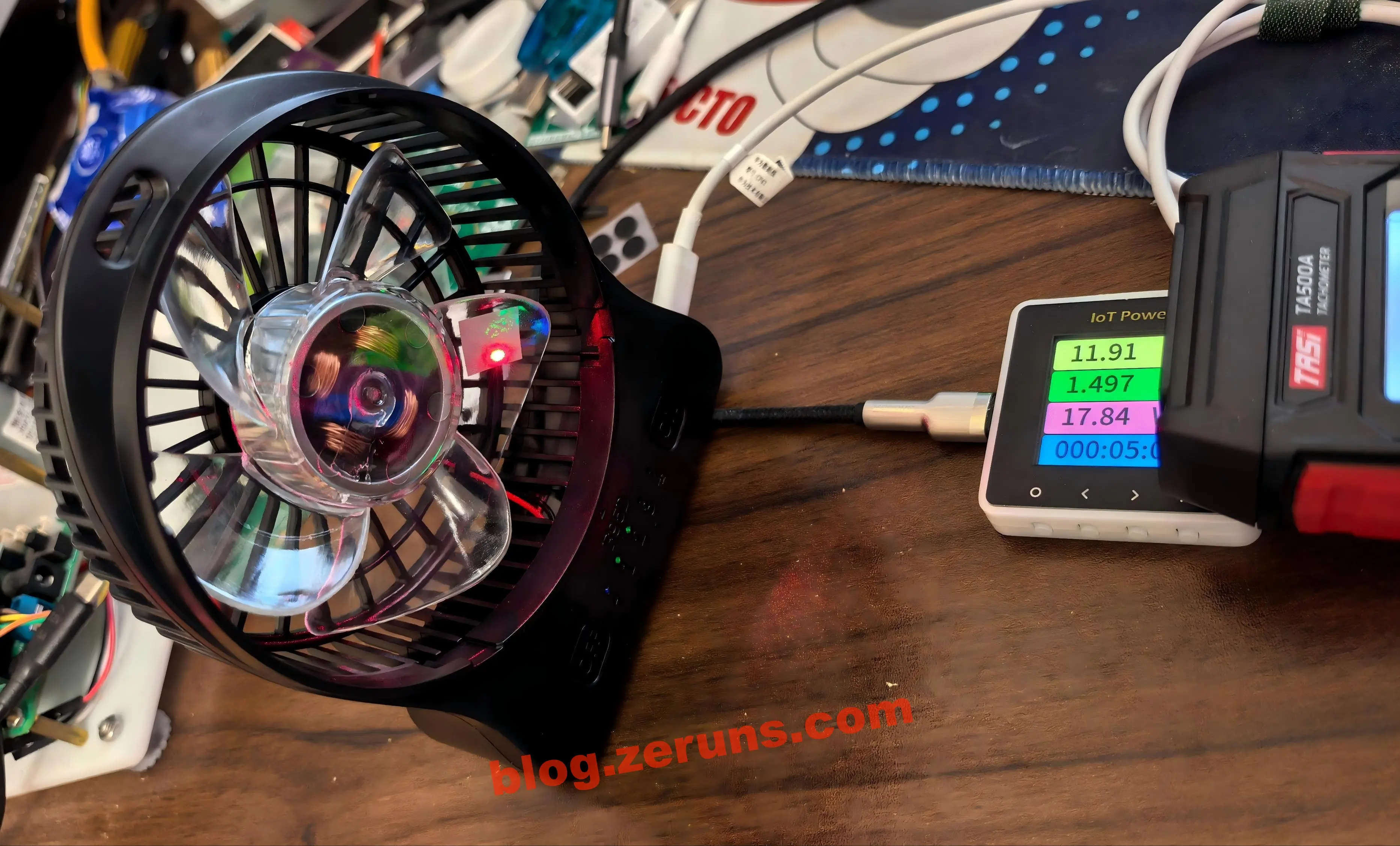
I used the TENMARS TA500A laser tachometer to test the fan speed. First, a reflective sticker needs to be attached to the fan blade.
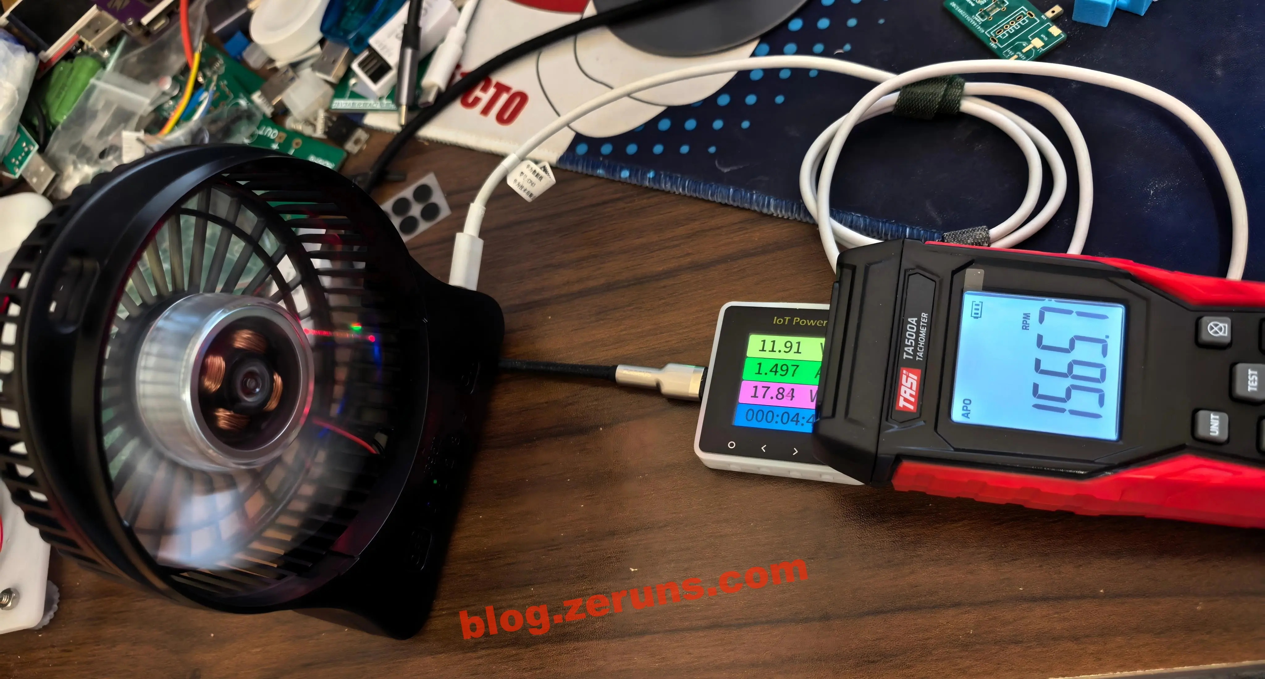
First-speed rotation: 1565 RPM. (RPM: revolutions per minute)
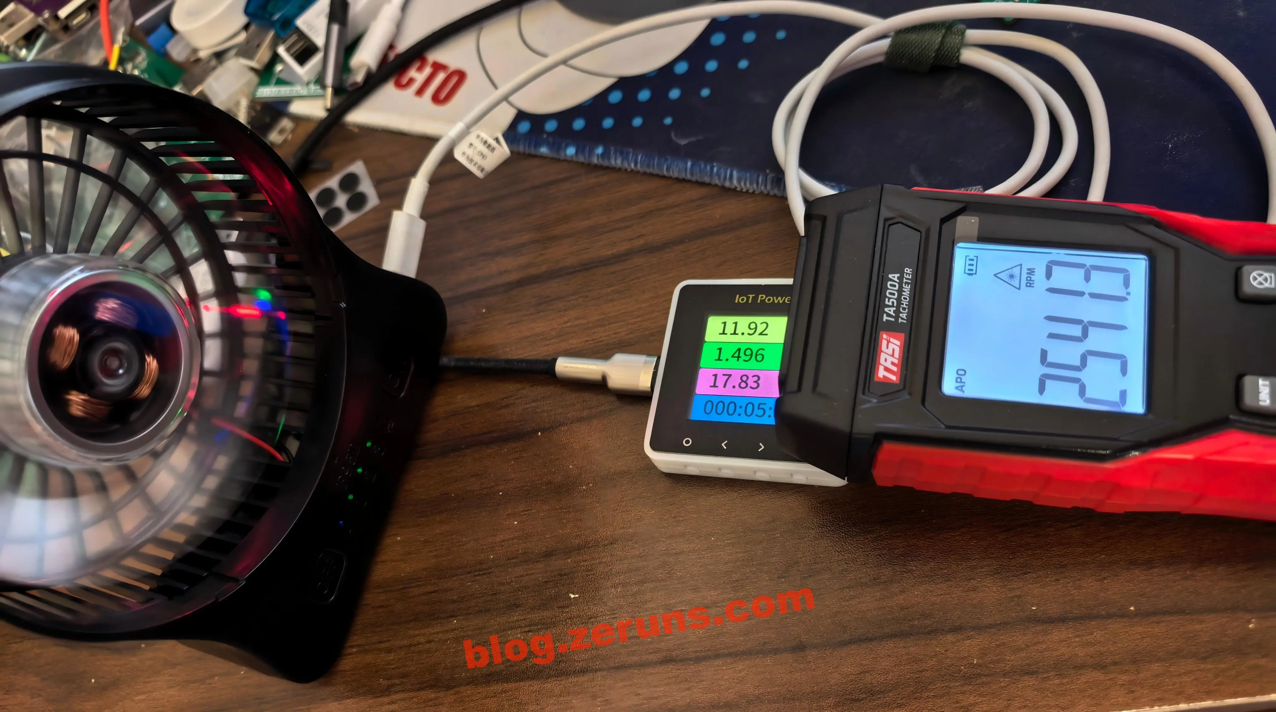
Second speed: 2541 rpm.
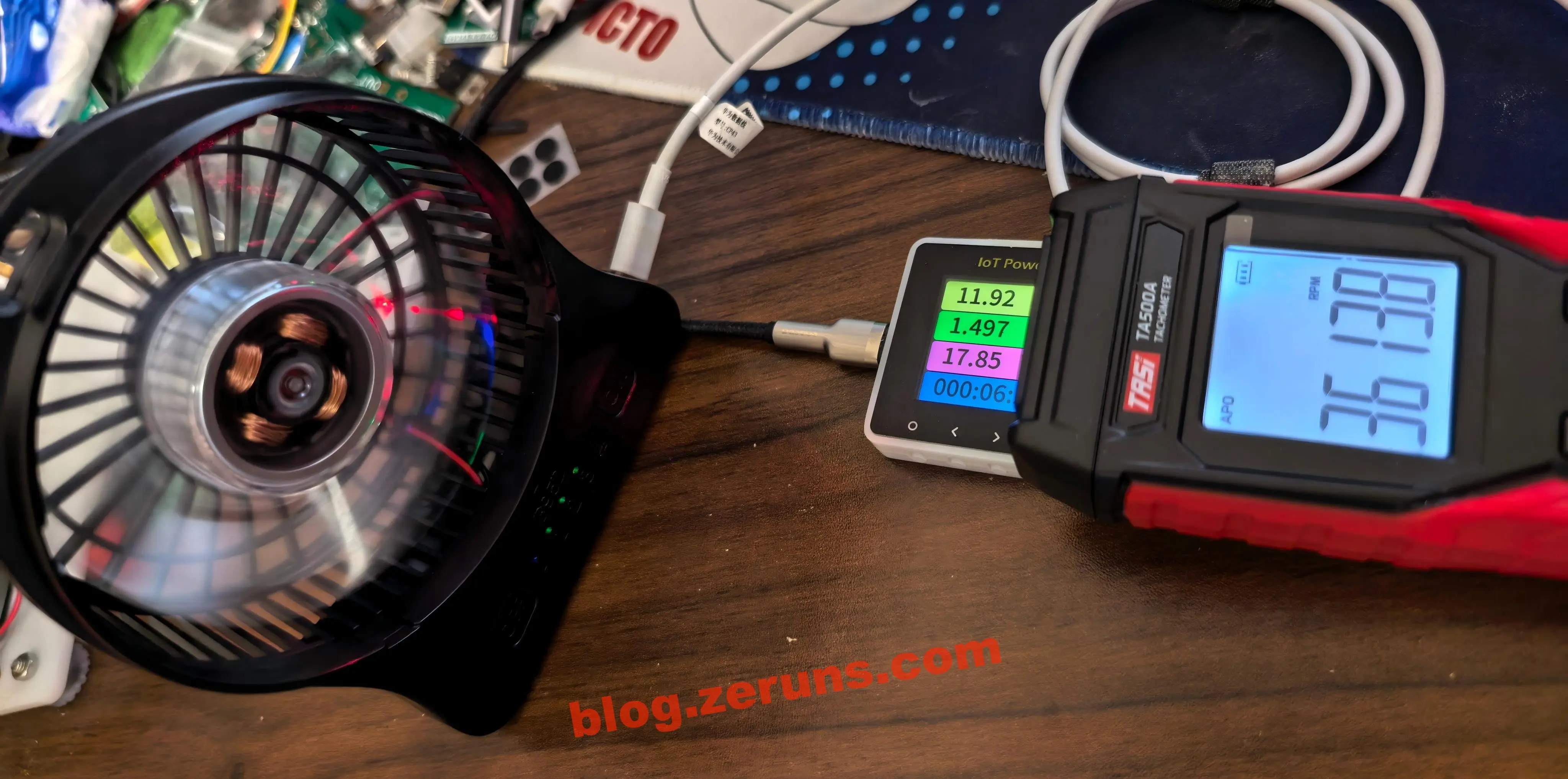
Third-speed rotation: 3613 RPM.
Fourth-speed rotation: 4695 RPM.
Teardown
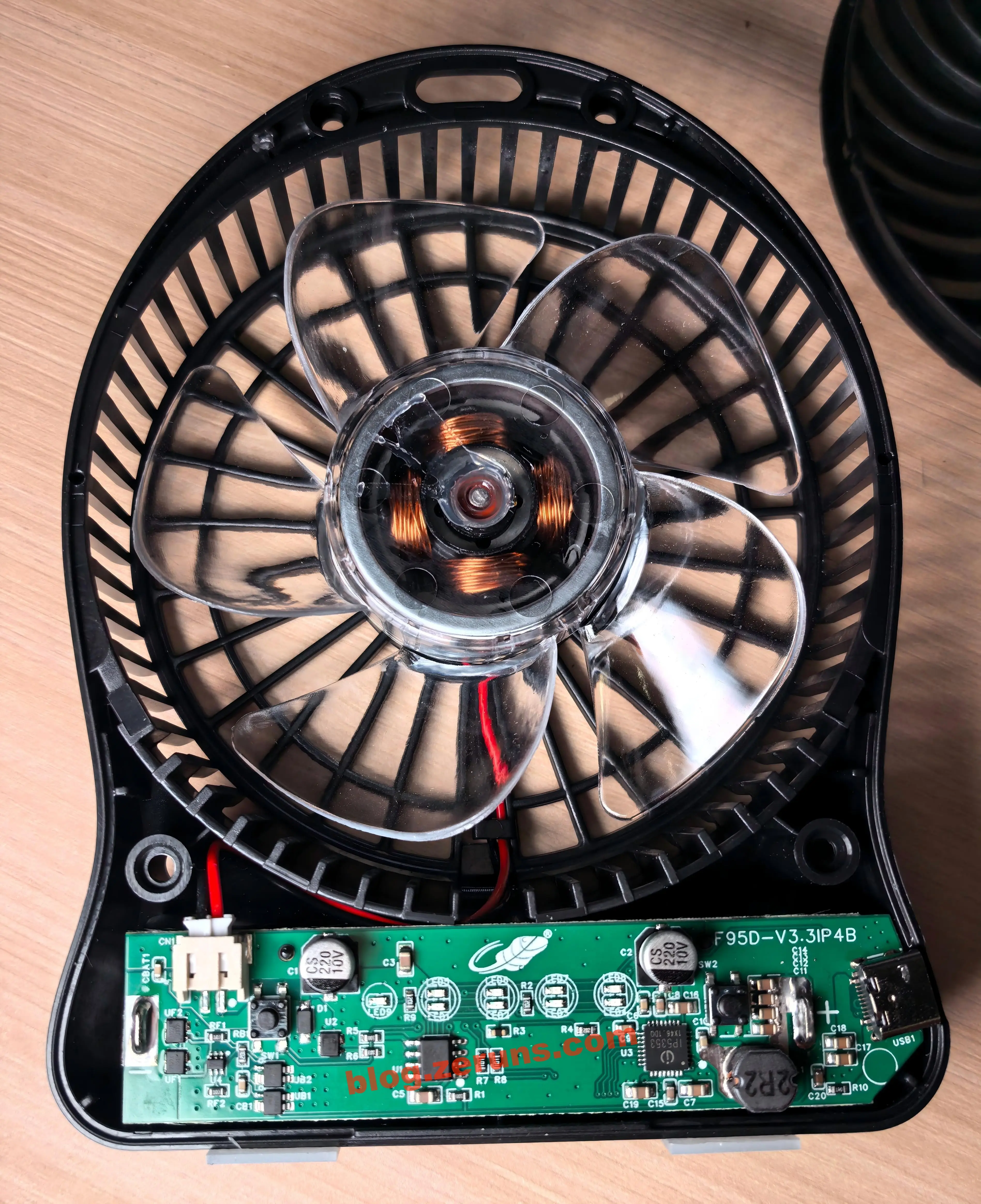
Unscrew the 4 screws on the back of the fan, and the front panel can be removed. The motor has 4 sets of stator coils, which should be a two-phase BLDC (brushless DC motor), and the wire from the main board to the motor is 2P.
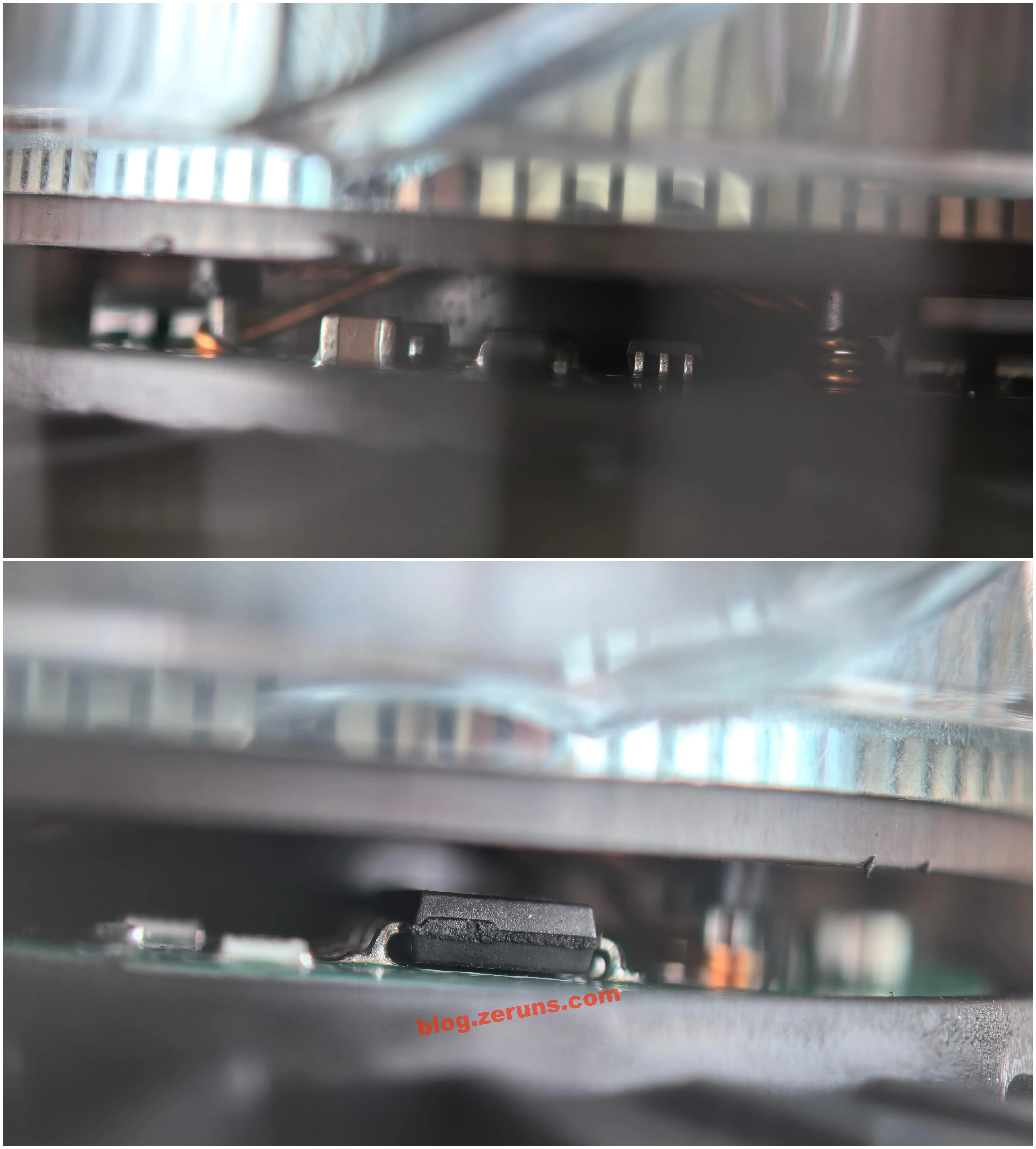
Viewed from the side of the motor, the bottom of the motor has a drive circuit. This motor should be the same type as those used in cooling fans: 2-phase, 4 sets of coils, with a built-in drive circuit.
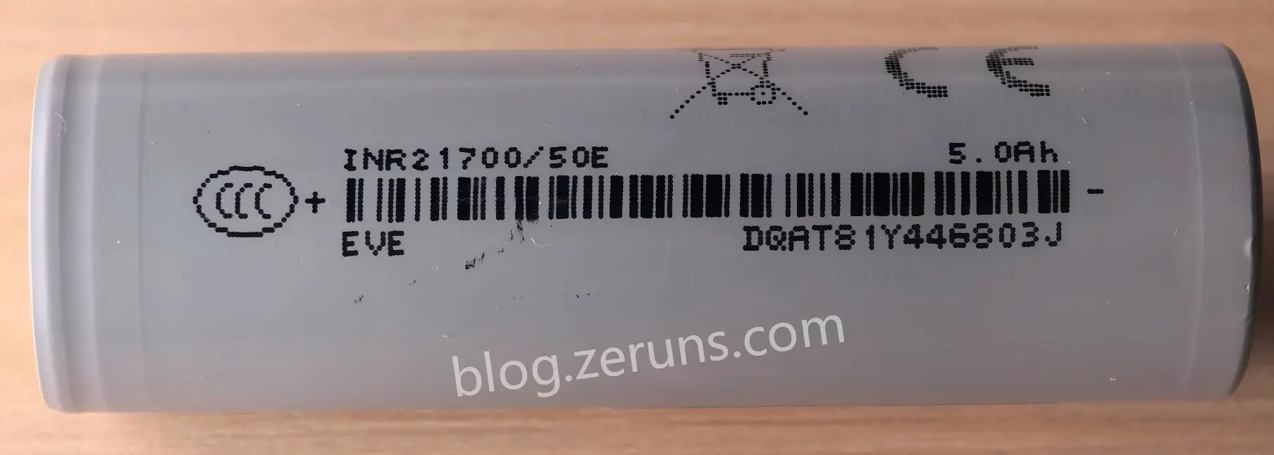
The included battery is an EVE INR21700/50E cylindrical ternary lithium-ion cell. Its nominal capacity is 5000mAh, it is marked with the 3C logo, and its cell size specification is 21700, with a diameter of 21mm and a height of 70mm.
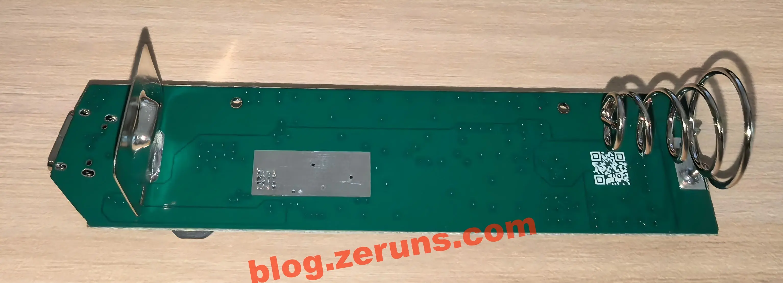
After removing the main board, you can see that the back of the board has through-hole battery holder contact tabs soldered on, and a QR code is also printed on it. The information scanned from the QR code is F95D-V3.3IP4_1cq9n5_21787. There is also a rectangular solder-mask opening area in the middle of the PCB, which is used for heat dissipation by the fast-charging chip.
Front side of the main board. The model and version number F95D-V3.3IP4B are printed in the upper right corner. The Gongtian logo is in the middle, along with 9 LED indicators.
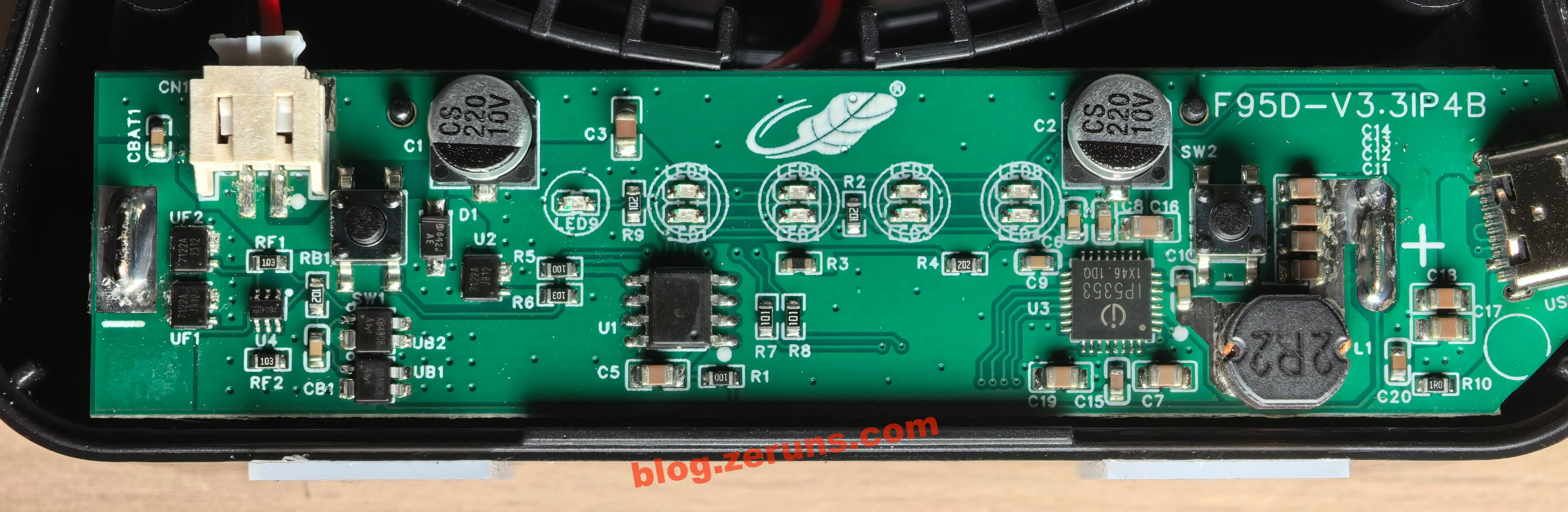
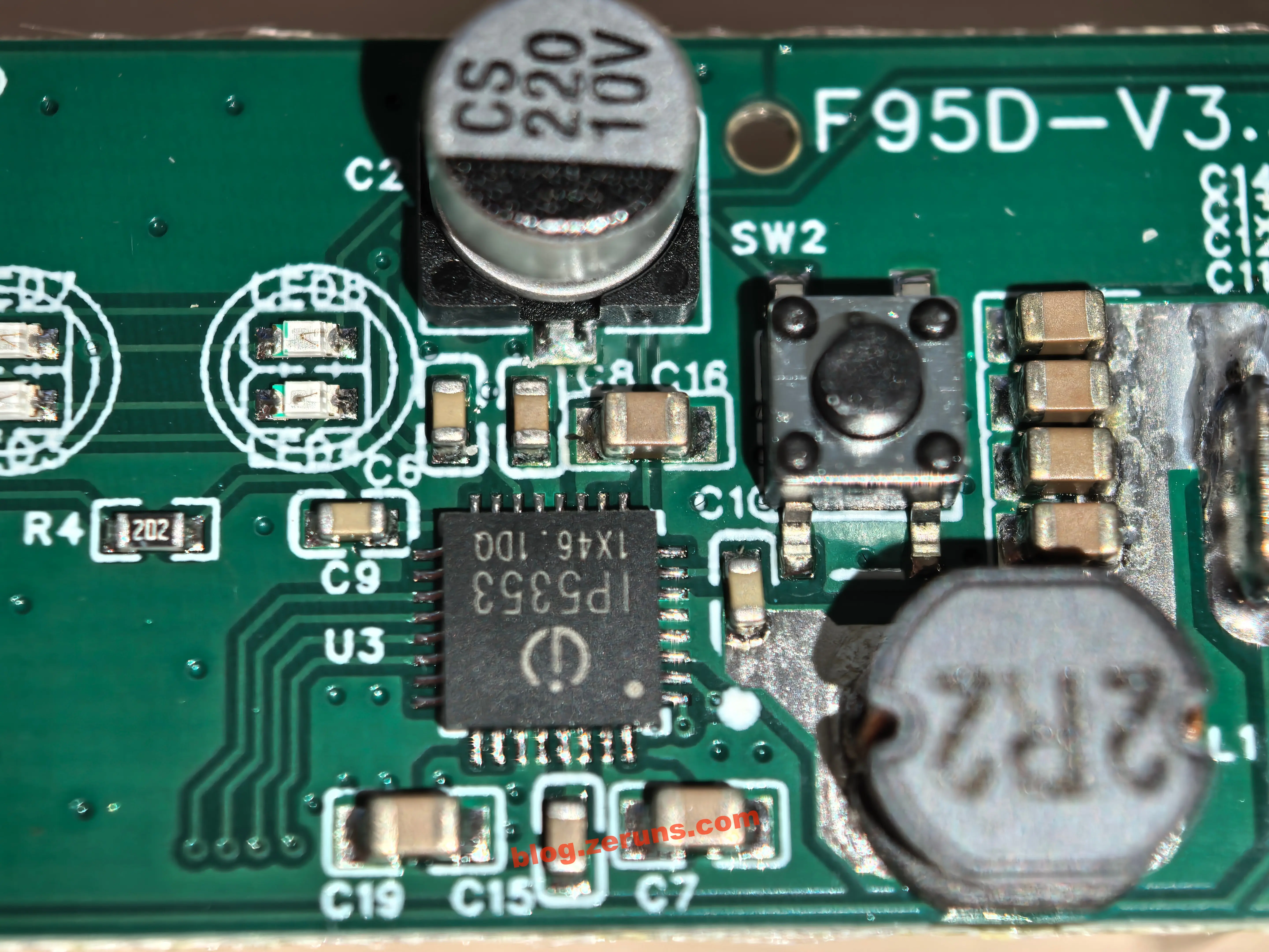
First, let’s look at the charging circuit. The charging chip model is IP5353, a power bank power-management SoC from INJOINIC in Zhuhai. A single chip handles the lithium battery charging, boost output, and battery-level indication for this fan.
IP5353 Core Specifications (AI-generated):
Core functions: Integrates synchronous boost/buck conversion and lithium battery charging management, has a built-in power MOS, uses a single inductor for charging and discharging, and supports buttons, 4-LED battery indication, and lighting drive
Fast-charging protocols: Supports PD2.0/PD3.0 (including PPS), QC2.0/QC3.0, Huawei SCP, FCP/AFC, and is compatible with BC1.2/Apple/Samsung
Charging and discharging specifications: 18W charging, maximum battery-side current of 5A; maximum discharge of 22.5W ([email protected] / [email protected] / [email protected]), with 95% efficiency at 5V@2A
Package and batch: QFN32 SMD package (5mm×5mm). The integrated molded power inductor beside it confirms the single-inductor design. The silk-screen marking
1X46.1DQis batch informationApplication positioning: Commonly used in fast-charging power banks and portable energy storage; here it is cross-used in the charging circuit of a portable fan
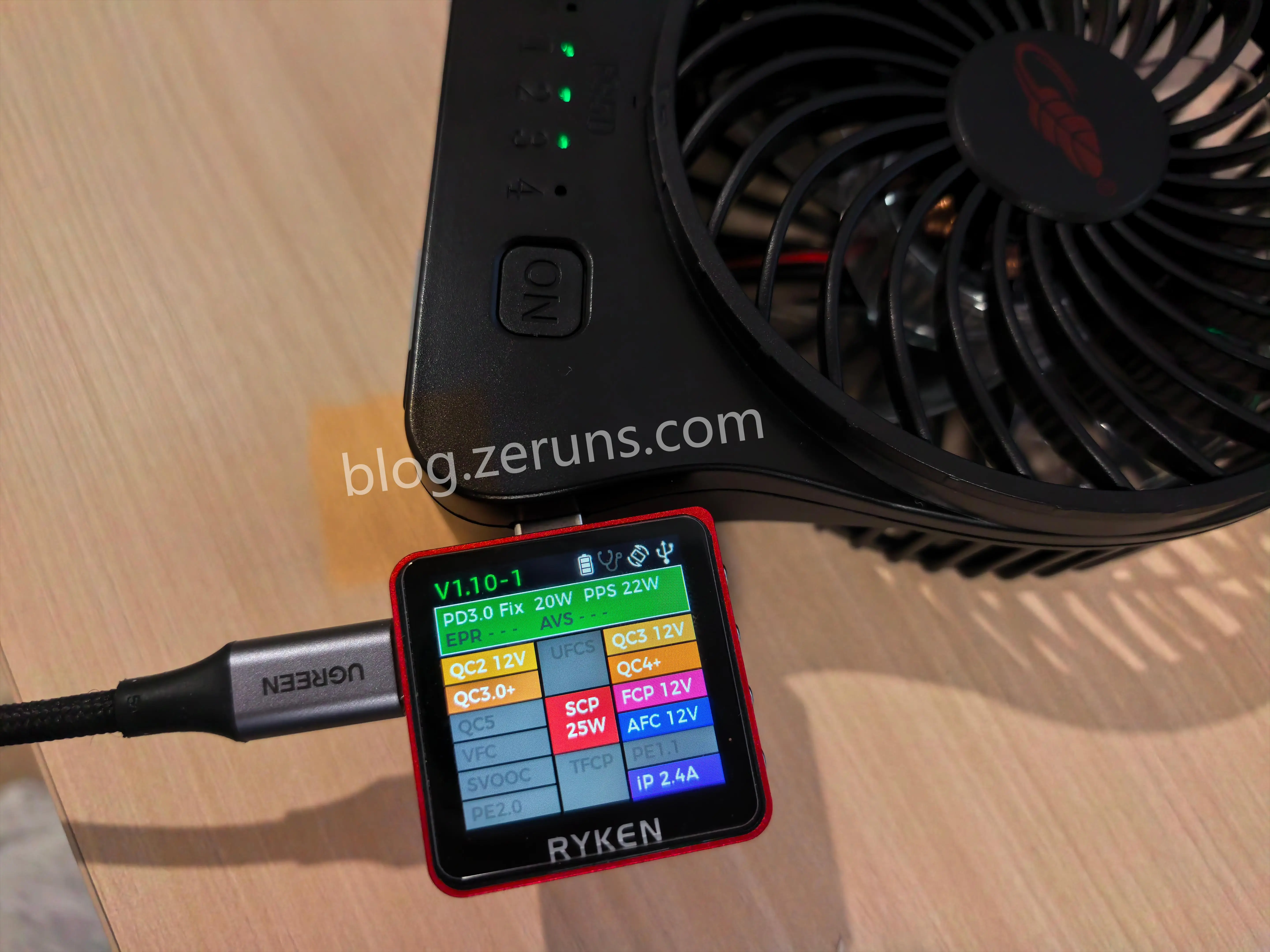
Next, I used the RK-X3 Pro fast-charging tester to check which fast-charging protocols the fan’s USB-C output supports. It supports PD22W, SCP25W, QC, FCP, AFC, and other protocols.
There is an 8-pin chip in the middle of the PCB whose silk-screen marking has been ground off. It should be a microcontroller (MCU), responsible for speed-level switching and display, as well as outputting PWM to control the fan speed. Pin 1 of this chip should be the positive power supply. The power supply passes through RC filtering and then goes to pin 1 of the chip. Pin 8 should be GND.
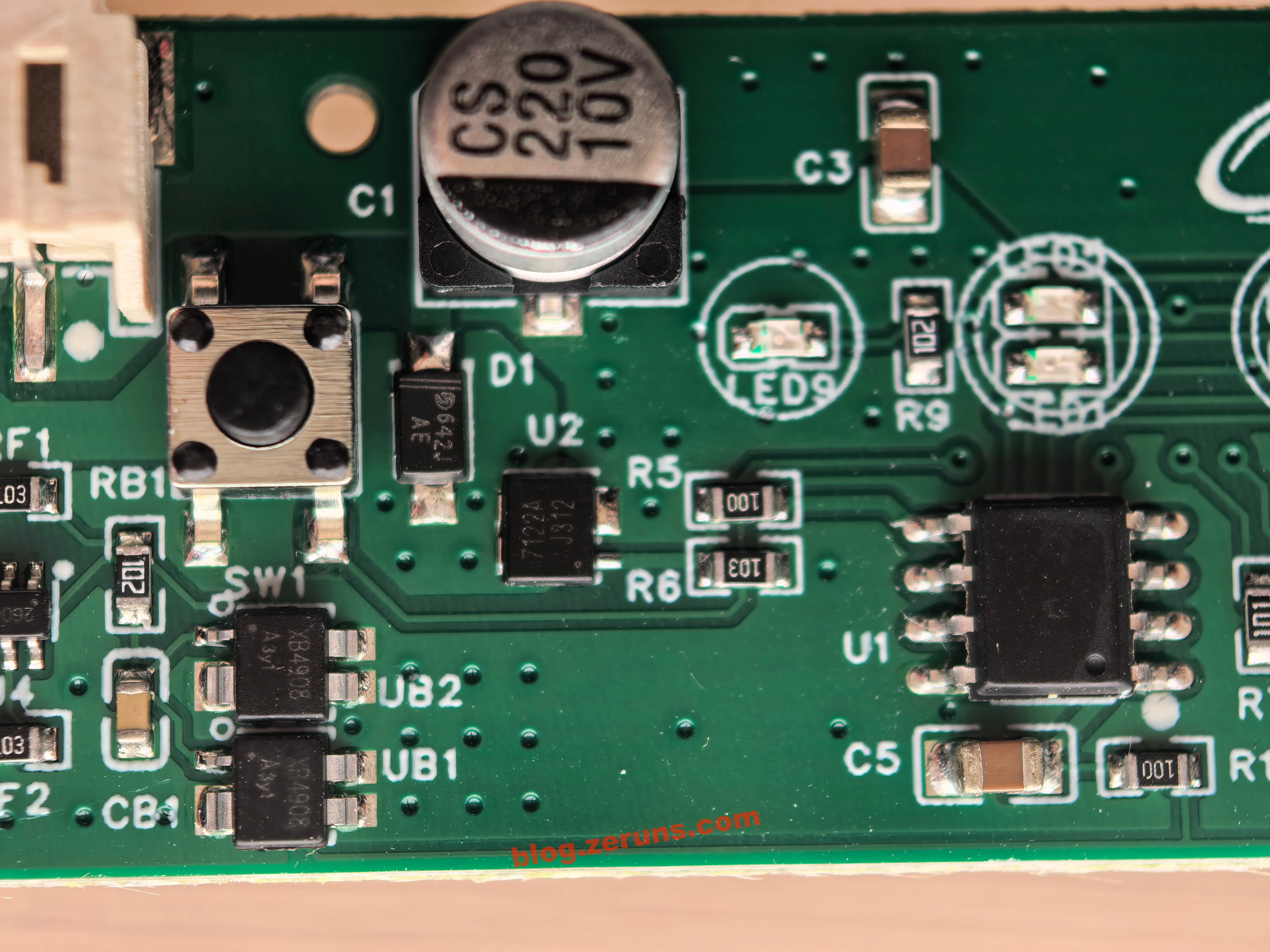
U2 is an NMOS chip with the silk-screen marking 7122A. I couldn’t find the datasheet for this MOS. The MOS gate is connected to pin 5 of the MCU through a 10Ω resistor. The MOS drain (D) is connected to the motor’s black wire, and the source (S) is connected to GND. The fan speed is controlled by adjusting the on/off time ratio (duty cycle) of the negative side of the motor power supply.
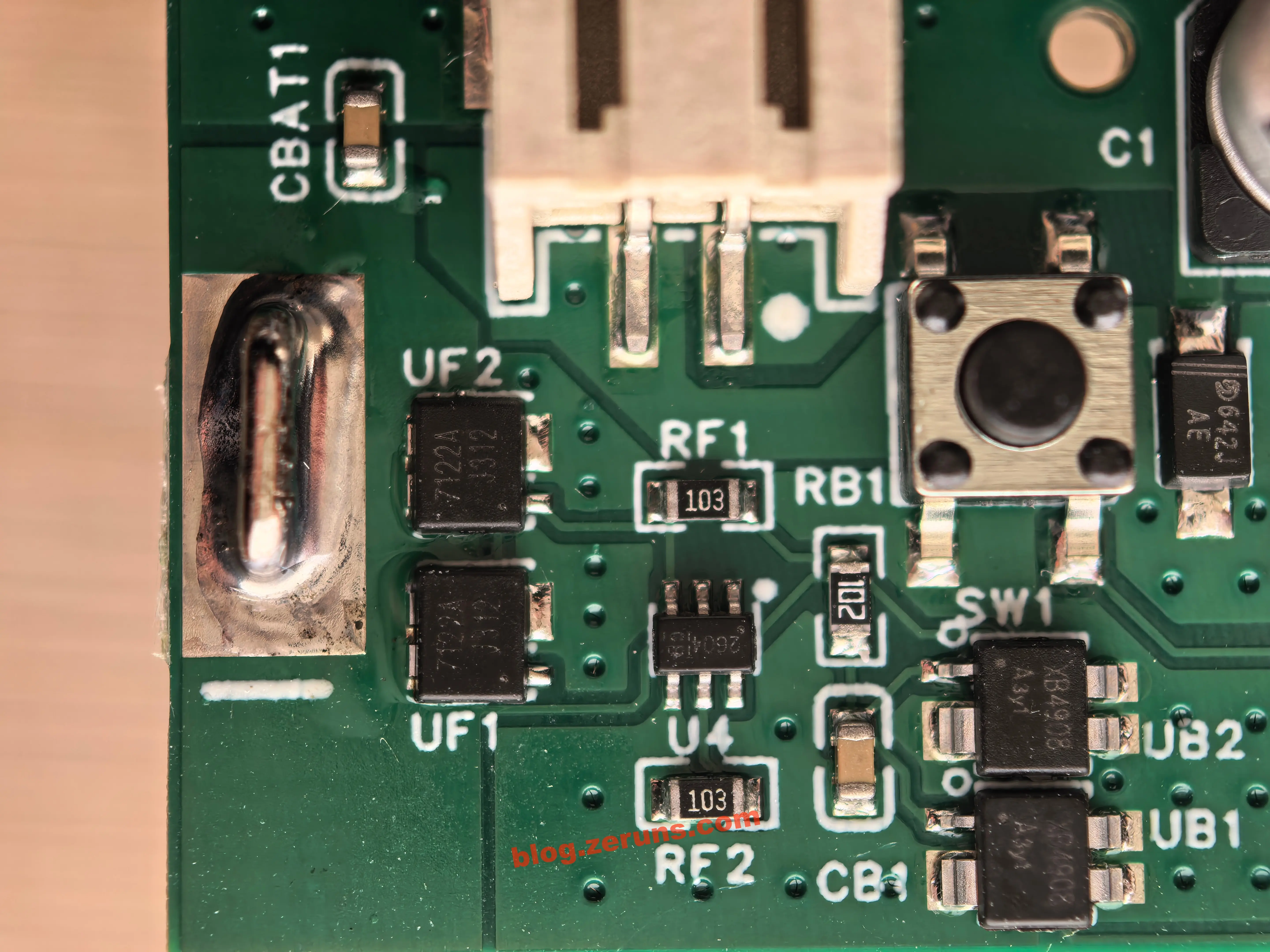
The circuit below the fan connector also has an independent lithium battery protection circuit near the battery negative pad. It consists of one protection IC 2604 (designator U4), two 7122A MOSFETs (designators UF1/UF2), and two Suzhou XINLITIAN Microelectronics XB4908 2-in-1 protection ICs (designators UB1/UB2).
Motor Control Waveforms at Different Speed Levels
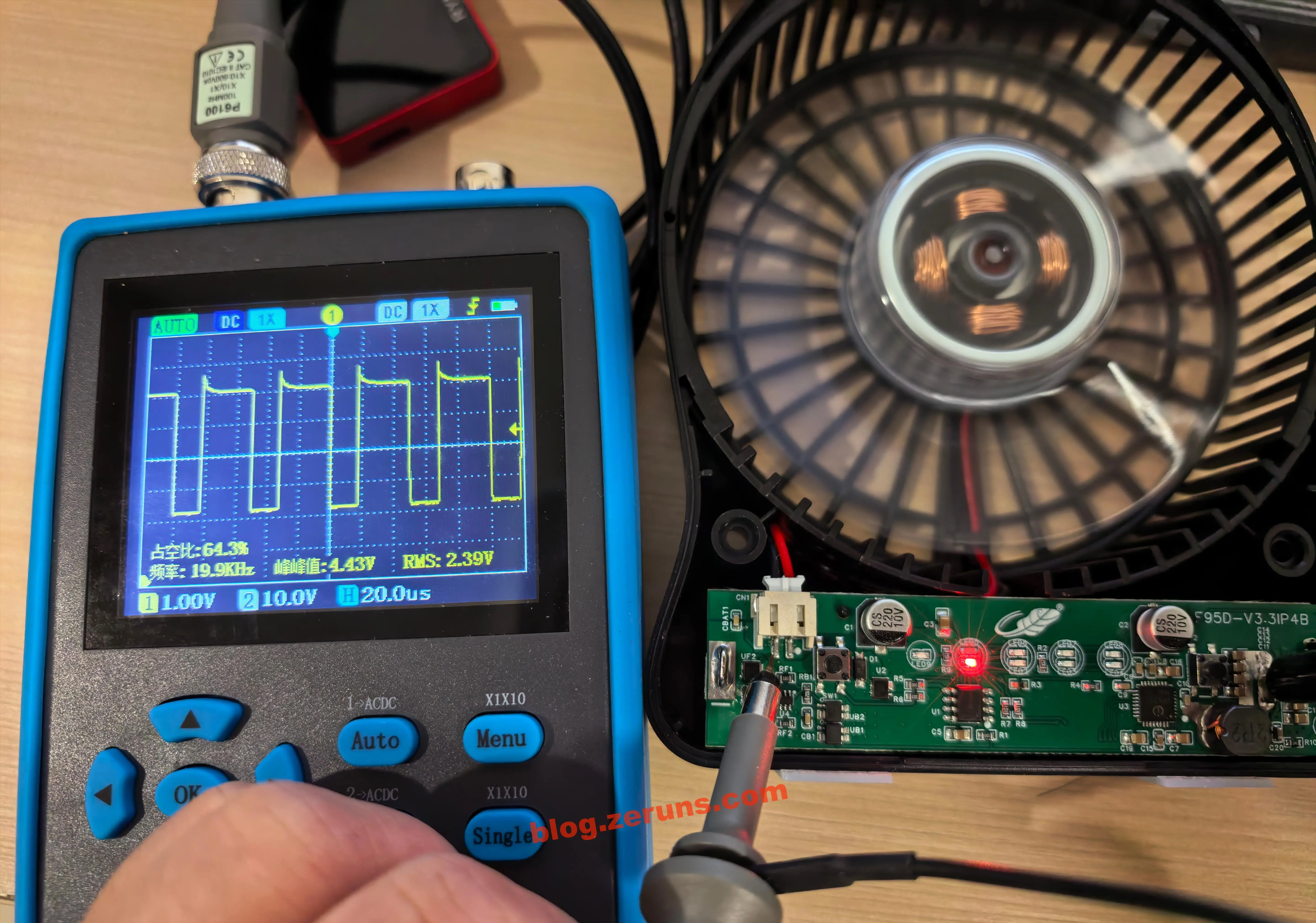
I used an oscilloscope to measure the waveform on the motor power line. The probe positive lead was connected to the motor negative terminal, and the probe negative lead was connected to the motor positive terminal. With the fan at first speed, the measured PWM frequency was 19.9kHz and the duty cycle was 35.7% (because the probe was connected in reverse, the waveform and duty cycle are both inverted).
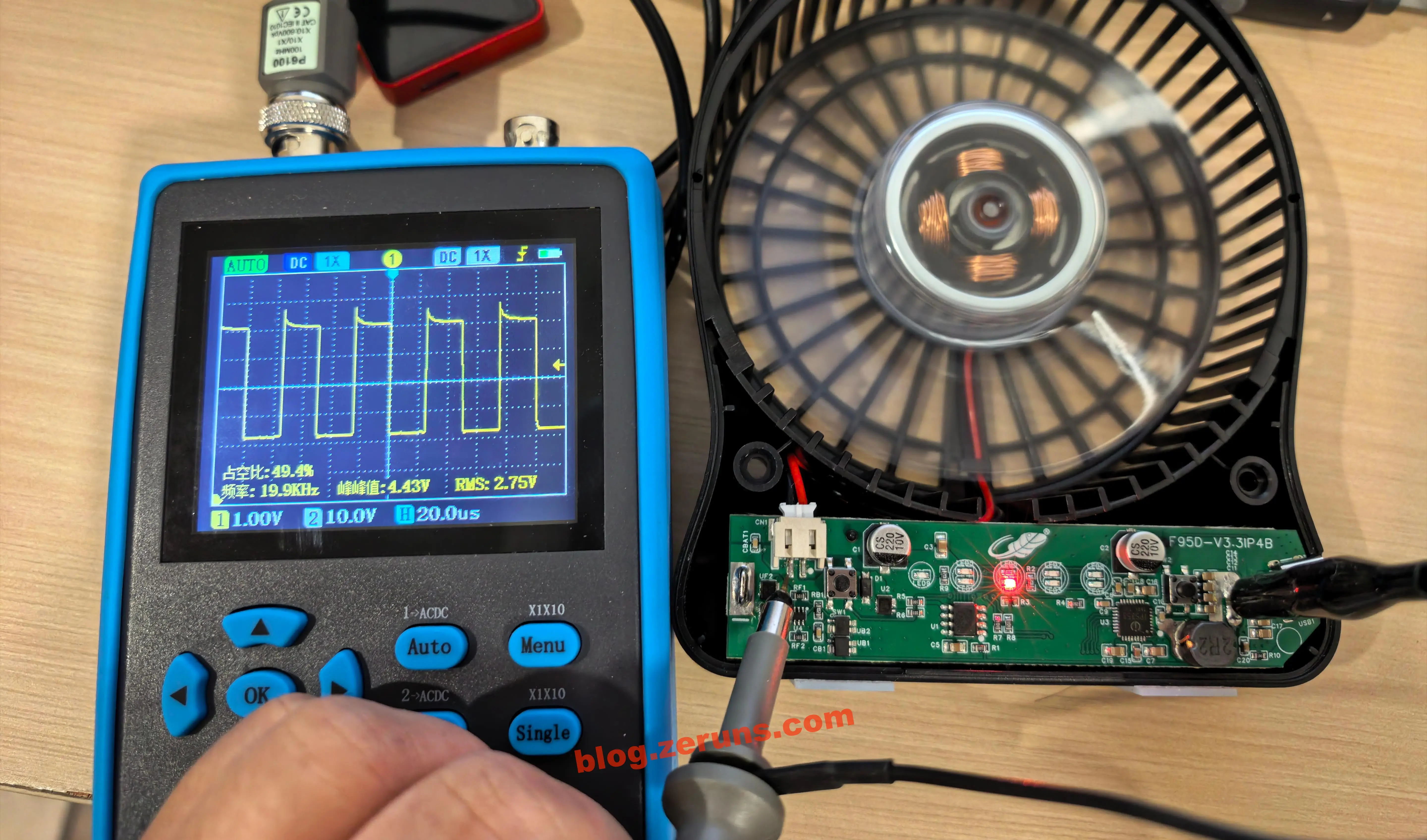
Fan at second speed. The measured PWM frequency was 19.9kHz, and the duty cycle was 50.6%.
Fan at third speed. The measured PWM frequency was 19.9kHz, and the duty cycle was 70.6%.
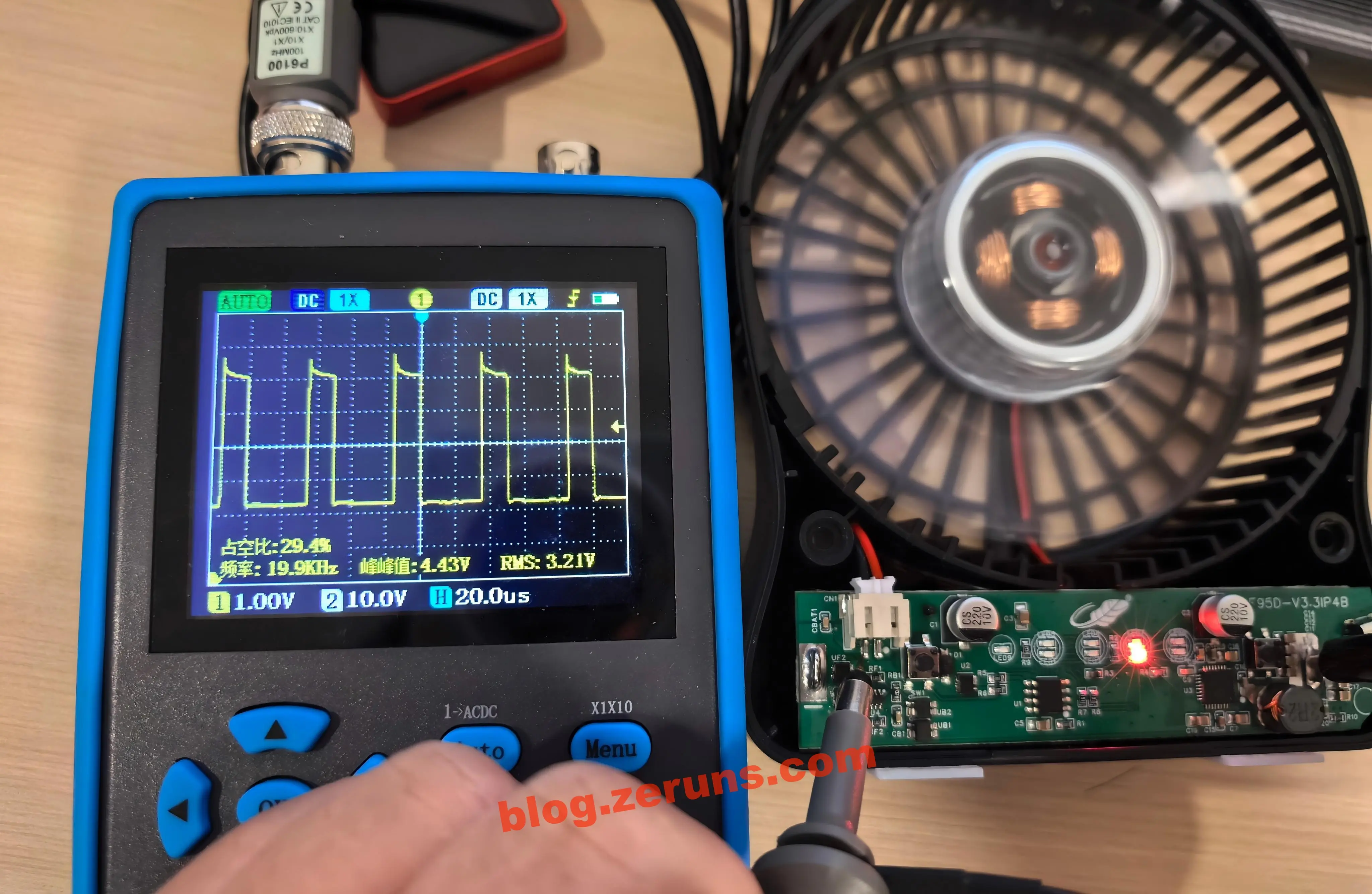
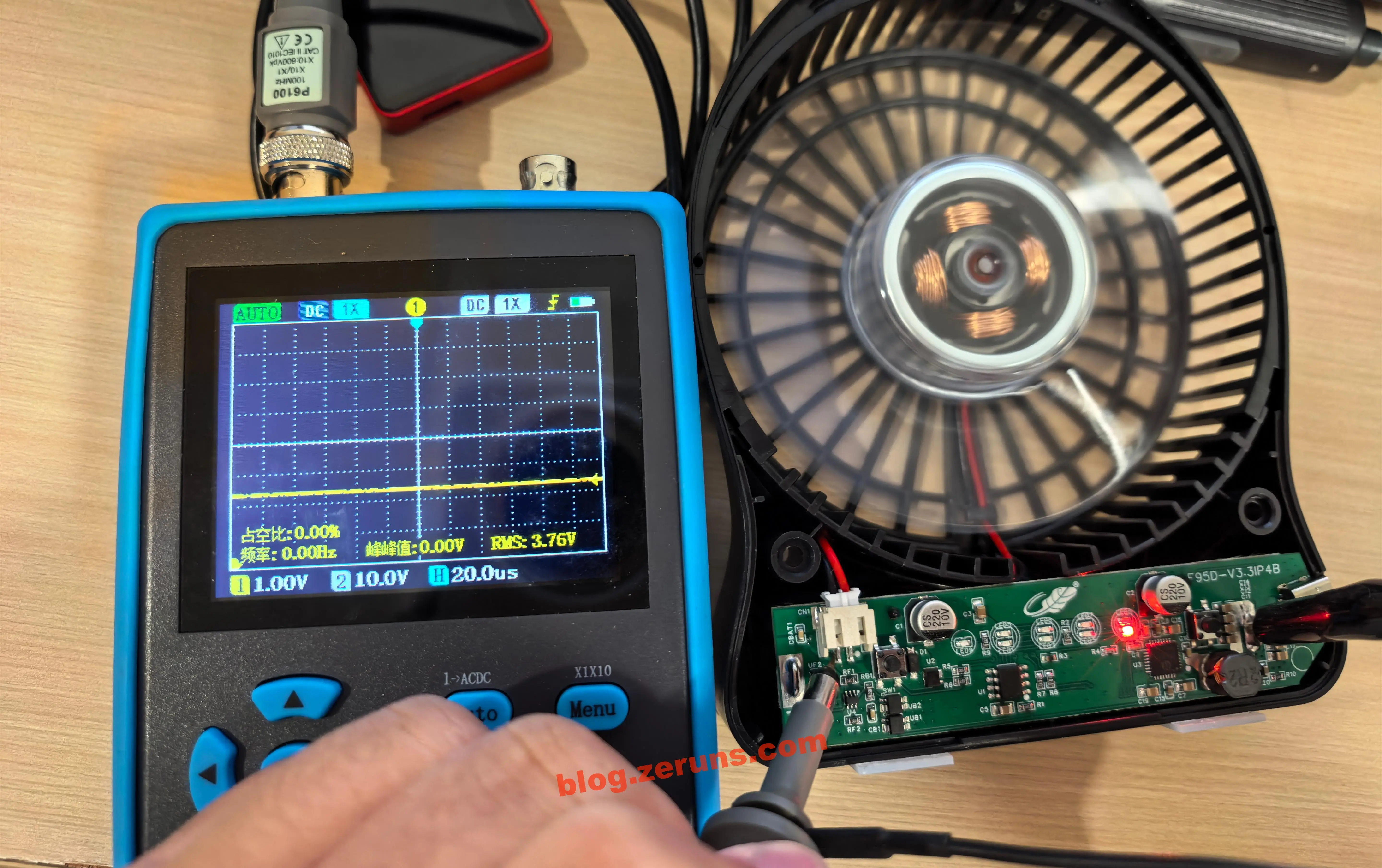
Fan at fourth speed. The duty cycle was 100%, meaning it remains continuously on.
Recommended Reading
- High value-for-money and affordable VPS/cloud server recommendations: https://blog.zeruns.com/archives/383.html
- Recommendations and introductions to AI large-model API platforms from various providers: https://blog.zeruns.com/archives/947.html
- Minecraft server setup tutorial: https://blog.zeruns.com/tag/mc/
- Complete guide to Hermes Agent deployment, a step-by-step tutorial for building your first AI assistant: https://blog.zeruns.com/archives/939.html
- Ugreen DXP4800Pro NAS unboxing review and teardown: https://blog.zeruns.com/archives/949.html
- OWON HDS160 oscilloscope-multimeter simple unboxing review and teardown: https://blog.zeruns.com/archives/927.html
English Version of the Article: https://blog.zeruns.top/archives/98.html