Questions about studying oscillator circuits and ultrasonic atomizer driver circuits

I’m an electronics hobbyist, and I’m currently trying to build the driver circuit for an ultrasonic atomizer. Before getting started, I’ve been studying this driver circuit a bit, and my conclusions so far are as follows:

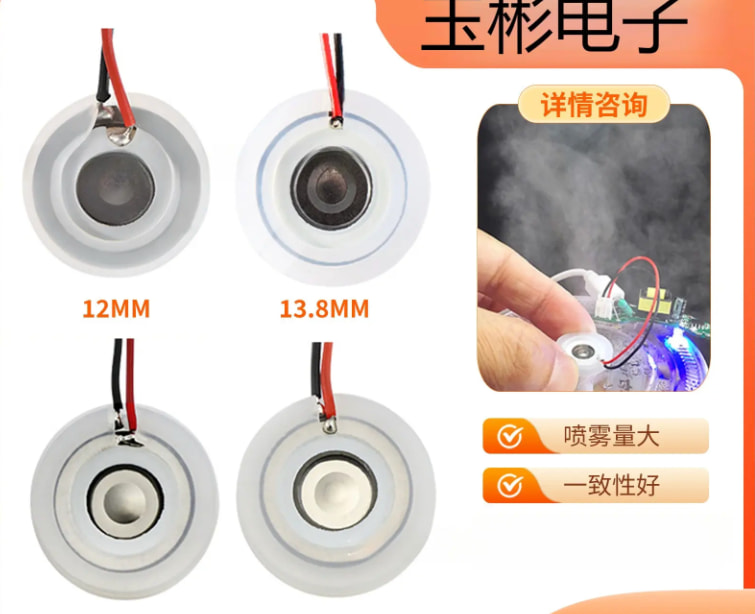
  1. An ultrasonic atomizer works by using a piezoelectric ceramic disc to vibrate rapidly and break water into tiny mist droplets, thereby producing mist;

  2. There are currently two types of atomizing discs on the market: ultrasonic atomizing discs and microporous atomizing discs. The difference between them is that the former operates at high frequency, while the latter has a lower frequency.

  1. To drive the atomizing disc, an oscillator circuit is needed to generate an AC signal.

The issue I’m currently stuck on is this oscillator/driver circuit. I’ve been looking up information online and in discussion groups, and my current understanding is as follows:

  1. The two most basic components of an oscillator circuit are the inductor and capacitor, which exchange stored energy and potential energy. During this process, the polarity of the inductor reverses, and this is the key to generating AC;

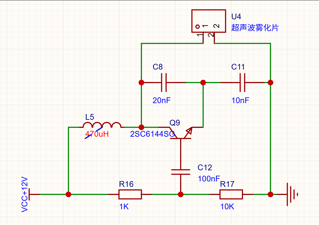
  2. Based on what I currently want to build, I plan to use a three-point capacitive oscillator circuit (below is the schematic I sketched out; the specific component selection and parameters have not been finalized yet)

For component selection, I first determined that the atomizing disc frequency is 1.7 MHz, then calculated the value of image backwards from the desired frequency. My result was 9.36×10^-8.

  1. A (amplification factor) * β (feedback coefficient) > 1. In the materials I looked up, it says 3∼5. Most sources write |A*β| as being in this range, but since our goal is to generate oscillation, it should be a positive value, producing an amplifying effect.

  2. The capacitance values are the combined capacitance of C8, C11, and the atomizing disc. The β feedback coefficient is image

  3. The base and the center tap of the bias resistor are equivalent to AC ground, so a capacitor needs to be connected in parallel.

As the saying goes, it all makes sense when you read it, but falls apart as soon as you try to do it. I feel like I don’t really understand it that well from reading, and actually building it is even more difficult. The points I’m currently stuck on are:

  1. First, apart from the capacitance value of the atomizing disc, which I can calculate directly, how do I calculate the values of the other two capacitors? For now, I only found an empirical rule for the product of A and β, and I don’t know exactly what the value should be, so I can’t work backward to determine the specific values of C8 and C11. I also can’t calculate the inductance value.

  2. What criteria should be used when selecting the capacitor for AC grounding at the base?

  3. Is this driver circuit correct? If I want to control the mist output, could I add a power MOSFET at the front end of the driver circuit’s GND and use a square wave to control the average power, thereby indirectly controlling the mist output?

  4. Could experienced folks take a look and tell me whether the circuit is correct?

I hope experienced folks can take a look, give me some comments, and let me know whether my line of thinking is correct

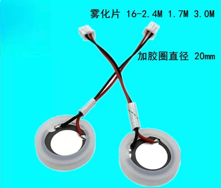
The OP is heading in the right direction, which I’ll acknowledge first. A three-point oscillator (Colpitts) is indeed the mainstream traditional architecture for driving atomizer disks, and the 1.7 MHz choice is also a common specification (the kind of disk marked 1.7M/2.4M/3.0M with a 20 mm diameter). But there are a few things to watch out for:

  1. Don’t expect to calculate C8, C11, and L accurately using formulas alone. The atomizer disk is not a pure capacitor; it is a composite model of “static capacitance C0 + motional branch.” The nominal value and the measured value can differ a lot, and different manufacturers vary wildly. The correct approach is to measure C0 with an LCR meter, then tune the resonance around that.

  2. The L value is probably wrong. The 470 µH shown in the diagram is far too large. The rule for this kind of circuit is straightforward: the inductor must resonate with the atomizer disk’s parallel capacitance. Working backward from 1.7 MHz, with a total capacitance of 2–3 nF, L is only 1–3 µH (online DIYers using 25 W disks have used 1–2 µH + 3.3 nF for resonance). With 470 µH, no matter which capacitance range you pair it with, the resonant frequency drops to tens of kHz, putting the disk far outside its resonance point; atomization efficiency becomes extremely low, or it may not oscillate at all. You can calculate it yourself to verify: f = 1/(2π√(LC)).

  3. Check the units on your 9.36×10⁻⁸. If it is in farads, that is 93.6 nF, an order of magnitude larger than the parallel capacitance expected for an atomizer disk (nF range). You probably used the wrong formula or chose the wrong L value. At 1.7 MHz, C should be in the few-nF range.

  4. Base AC-grounding capacitor: The selection principle is to make its capacitive reactance Xc at the operating frequency ≤ 1/10 of the impedance being bypassed. In general, 100 nF is safe; no need to split hairs.

  5. A×β: For oscillation to start, the loop gain must be ≥ 1 and satisfy the Barkhausen criterion (including the transistor’s 180° phase inversion). A value of 3–5 is an engineering rule of thumb for margin; it can only be treated as a target, not used as the sole basis for back-calculating C8/C11.

  6. Note that this disk is high-power. 1.7 MHz disks are usually used in humidifiers above 15 W, with common supply voltages of 12–24 V. You are only supplying 12 V, so the drive margin is rather tight. Since the transistor is also operating in the linear region, heat dissipation will be significant; use a large heatsink and, if possible, verify the disk’s rated power.

  7. Mist control. The traditional method is adjust base current (potentiometer) → change the voltage across the atomizer disk → adjust mist output. The 50–80 V peak-to-peak shown in the diagram is raised there by inductive step-up. The MOSFET intermittent/PWM method you added can also work and is a feasible DIY approach, but pay attention to the minimum duty cycle—if it is too low, oscillation will stop. New production designs have already moved to MOSFET switching + MCU frequency sweeping/tracking (for 1.7M disks, the sweep is generally 1.55–1.85 MHz).

I’d suggest not trying to get everything perfect in one step. First, replace L with 1–3 µH and change the feedback capacitors to the nF range, then get oscillation running: power it up and see whether the current jumps, listen for a “buzzing” sound from the disk, and use an oscilloscope to check for a sine/triangle-ish wave near 1.7 MHz. Post the waveform, and we can fine-tune from there.

“Easy to understand at a glance, but useless as soon as you try it” is completely normal. The trap with this circuit is that the Colpitts formulas from the textbook don’t fully apply here. Let me walk you through it.

1. Why can’t you calculate C8/C11? Because you’re not supposed to calculate them that way. The misting disc here isn’t “a capacitor”; it’s a piezoelectric resonator (you can think of it as a 1.7 MHz crystal oscillator). Using the Van Dyke model, it has a static capacitance C0≈1600~1900 pF (you calculated this correctly; an LCR meter at 1 kHz can measure it directly), in parallel with a mechanical branch Lm-Cm-Rm. Between fr and fa, it behaves overall as inductive—so in this circuit it acts as the “inductor,” and the oscillation frequency is locked to its own mechanical resonance. That’s why the manufacturer says “this circuit can automatically follow the natural frequency of the piezoelectric oscillator and avoids frequency adjustment.”

So the correct approach is: the disc sets the frequency; L/C only controls amplitude and feedback amount. The division of roles is—the parallel branch has a resonance point below the operating frequency (sets amplitude), while the series branch has a resonance point above the operating frequency; the closer it is to 1.7 MHz, the stronger the feedback (sets feedback). The feedback capacitor is not better the larger it is. If it’s too large and makes the b-e terminals inductive, oscillation will stop directly.

2. Your understanding of the A·β loop is fine. The Barkhausen criterion is |A·β|≥1 with 0° loop phase shift. The common-base configuration is inherently in phase, so it provides positive feedback. But don’t expect to derive C from A—A only needs to be “large enough,” while β is determined through tuning.

3. Your 470 µH inductor isn’t the problem. In real tests, people have used 47 µH and 150 µH with normal results, and mist output basically stops increasing above 47 µH. In this circuit, it mainly acts as energy storage / a current path.

4. But 12 V really won’t work. This is what you should change first. A 1.7 MHz solid-hole disc needs 50~80 Vpp excitation, and classic modules use a 33~50 V supply. The measured conclusion is very straightforward: 12 V can only lift the water; it can’t atomize it. Boost it to 24~36 V with an XL6009, or switch to a 113 kHz micro-hole disc and use a low-voltage solution.

5. Adjusting mist output: I’d recommend following commercial designs—use a potentiometer to adjust the oscillator transistor’s base current, changing the amplitude. If you want PWM, make it a second-level intermittent pattern like “run for 10 seconds, stop for 50 seconds” (the cycle scale in the patent is 0.1~10 s). Don’t hard-chop it at the kHz level; repeatedly starting away from the resonance point can damage the disc.

6. Base bypass capacitor: Xc ≤ Rth/10. With your 1k∥10k, at 1.7 MHz you only need ≥1 nF, so 100 nF is more than enough. Just use a high-frequency ceramic / NPO capacitor.

Hope you get mist output on the first try!

Thank you for your guidance. After reading it, I’ve reorganized my thinking about controlling the “mist output.” To keep the circuit running stably, I’ll keep the frequency unchanged and adjust the oscillation amplitude of the atomizing plate to affect the output. I think this is better than my previous idea.

At the moment, I don’t have an oscilloscope, and my power supply can’t provide 24 V or higher, so I’ll first make a few boost modules and then rebuild it to try again. I hope I’ll be able to successfully submit the assignment later.

Nice write-up — your grasp of the Barkhausen criterion is better than most. But there are three things I’d change before you solder anything.

First, 12V won’t get you fog. These 1.7MHz discs want 50–80Vpp across them; the classic commercial boards run 33–50V at roughly 0.6A. Someone actually measured this: at 12V the disc just throws up a water column, it doesn’t atomise. Boost to 24–36V (an XL6009 module is the usual hack), or switch to a 108–113kHz microporous disc which is happy on 5–12V.

Second, don’t derive the frequency from L and C. The disc is the frequency-determining element — treat it like a crystal in a Pierce oscillator. Unloaded, these self-oscillating boards run around 0.65MHz; connect the disc and it snaps to 1.7MHz. That’s the “auto-tracking” the manufacturers brag about. So your L/C network has two separate jobs: the branch whose parallel resonance sits below the operating frequency sets the amplitude, and the branch whose series resonance sits above it (the closer to 1.7MHz the better) sets the feedback. Push the feedback cap too far and the b-e port goes inductive and it just stops oscillating. One guy’s measurements: about 2000pF with an inductor ≥47µH for the parallel branch, and it still ran fine at 150µH — so your 470µH is not the problem people think it is.

Third, check the voltage rating, not the current. Your 2SC6144SG is actually a beast — 50V/10A/25W, fT 330MHz. Plenty of current and gain. But VCEO is only 50V and the collector sees the supply plus a good chunk of that 50–80Vpp swing. The usual spec for this job is ≥100V, ≥3A, fT ≥100MHz plus a heatsink (BU406 is the classic: 200V/60W), and a clamp diode across C-E. Also, low-VCEsat switching transistors tend to have a skinny SOA — running one in the linear region at 1.7MHz is asking for second breakdown.

Mist control: the commercial way is a pot on the base bias, varying the amplitude. If you want to chop it, use burst mode with a period in the 0.1–10 second range and an on-time at least twice the time from power-up to visible fog. Fast kHz PWM just re-starts the oscillator off-resonance over and over — inefficient, hot, and hard on the ceramic.

And the usual: coupling/DC-blocking cap (47nF), never run it dry, use a float/reed switch for level sensing rather than probes (probes electrolytically eat the electrodes), and keep the water 4–6cm deep.

73, good luck on the build.

Following the usual schematic-review flow, point by point:

  1. The topology is the traditional three-point type (Colpitts), so the concept is right. AC-grounding the midpoint of the base through a capacitor is the correct common-base behavior, so keep it.
  2. L5=470µH is mismatched with 1.7MHz (critical error). In this kind of circuit, the inductor resonates with the atomizing plate’s parallel capacitance. 1.7MHz + total capacitance of 2~~3nF → L≈1~3µH (in actual units, use 1~2µH + 3.3nF). No matter which capacitor value it is paired with, 470µH will resonate in the tens of kHz, so the plate will not be at resonance and efficiency will be extremely low.
  3. If C8=20nF and C11=10nF are intended as the resonant voltage-divider capacitors, they are too large. The resonant/feedback capacitors should be in the range of a few nF (around 3.3nF); these two look more like coupling or DC-blocking capacitors.
  4. β is not simply C8/C11. For an ideal divider, the ratio is roughly β≈C_fb/(C_fb+C_main), but in practice it is also loaded by the transistor’s input/output capacitance and the plate’s C0, so it must be calculated as a loaded voltage divider. A·β≈3~5 is an engineering target for oscillation margin, not the only solution—since you only have one frequency equation plus one margin condition, while C and L are two degrees of freedom, you must introduce another constraint (typically L sets the frequency, and the capacitor ratio sets the feedback).
  5. The transistor choice is fine; the issue is “linear heating.” The 2SC6144SG is a power transistor rated at 50V/10A/25W, fT≈330MHz, hFE≈200, so its 1.7MHz frequency response and power handling are adequate. The real pitfall is making a 25W-class load operate in linear amplification mode, which causes very significant heating, so the heat sink must be large; this is also why mass production has shifted to MOSFET switching plus medium-frequency sweep tracking (1.7M plate swept from 1.55~1.85MHz). If you continue using a BJT, derate it and calculate the thermal dissipation carefully.
  6. Base bypass capacitor: choose Xc to be ≤ 1/10 of the impedance being bypassed (at the operating frequency); 100nF is enough.
  7. PWM/intermittent mist control is feasible, but the mainstream approach is to adjust the drive voltage. Traditional designs use a potentiometer to adjust base current → change the voltage across the plate (50~80V peak-to-peak) → adjust mist output. Adding a MOSFET to interrupt the supply can also work, but you need to allow a minimum duty cycle (too low and oscillation stops), and the PWM frequency should be far from 1.7MHz.
  8. Supply margin. A 1.7MHz plate rated for high power (15W+) commonly uses 12~24V; your 12V supply is tight, so check the plate’s rated power and voltage tolerance.
  9. Verify first, then optimize: measure C0 → reselect L around 1~3µH → use a current probe to confirm oscillation → then discuss parameters. Post the waveforms and I’ll continue reviewing the circuit.

Hey, nice project — and your Colpitts instinct is actually right; that’s the classic self-oscillator these misting elements use. A few pointers from someone who’s been down this road:

  • The inductor is the thing to fix first. At 1.7MHz these elements want a small inductor — a few µH, matching the piezo’s parallel capacitance. On a real build I saw the spec call for ~2µH with a ~3.3nF coupling cap. 470uH is off by a couple orders of magnitude; it’ll put the resonance down in the tens of kHz and the element just won’t mist.
  • Don’t try to calculate everything on paper. The transducer is a ceramic resonator with a “static + motional” model, and its real capacitance is all over the place between suppliers. Measure it (LCR meter) and tune from there.
  • Base cap to ground: just needs its reactance at 1.7MHz to be small vs. what you’re grounding. 100nF is the lazy-but-safe pick.
  • Mist control: the traditional trick is adjusting the base current (potentiometer) — more base current means more voltage across the element (these run at ~50-80V peak-peak, boosted by the inductor) and more mist. A MOSFET to pulse the supply also works, but leave enough duty or it’ll drop out of oscillation.
  • Watch the heat. At 15W+ the transistor runs in linear mode and gets seriously warm — plan a real heatsink. Modern units switched to a MOSFET switching stage with frequency tracking for a reason.
  • And the usual killer: run the element dry and it’ll cook. Add a water-level sensor.

Good luck, and post your waveforms!